
Abstract
Many water-jet pumps have a suction velocity profile, which is non-uniform and unfavorable for the pump performance. This article applies the numerical method to investigate the generation mechanism of performance breakdown in a water-jet pump under non-uniform suction flow. The mechanism dictating flow details in the impeller, including the inlet velocity, flow angle, and boundary layer separation, is systematically studied at the design point. Observations show that the nature of non-uniform inflow is a circumferential distortion upstream of the impeller shroud, which is proved to be a stationary stall cell associated with a velocity deficit near the top sector. Meanwhile, a detailed analysis allows the identification of flow separation and vortex in the impeller. The circumferential distortion gives rise to a high incidence, the occurrence of suction surface separation, and the consequent formation of a concentrated separation vortex near the blade shroud. Furthermore, particular attentions are devoted to the pressure distribution and blade loading in the shroud section. Deviating from the suction surface, the concentrated separation vortex produces a considerable pressure rise on the suction surface and generates a remarkable drop in blade loading. Consequently, the concentrated separation vortex associated with circumferential distortion is a major reason for the head breakdown of a water-jet pump.
Introduction
The water-jet propulsion system is widely used to thrust high-speed marine vessels due to its relatively high propulsive efficiency, good maneuverability, and less vibration over conventional propellers. 1 During operation, the fluid below the hull is strongly ingested through the intake duct and worked by the pump and then the reaction force of discharging fluid drives marine vessels. Hence, the water-jet pump and intake duct are the key components in the complete water-jet propulsion system. In the system, the suction flow is non-uniform imposing onto the impeller because it is positioned closely to the upstream duct. 2 Besides, non-uniform suction flow exerts an unfavorable influence on pump performances.2–4 In order to control and even avoid the performance breakdown of a water-jet pump, it is very important to understand its generation mechanism under non-uniform suction flow.
As for the non-uniform suction flow to the water-jet pump in the complete system, many researchers have been aware of its existence and try to identify the origination and structure of non-uniform inflow by numerical or experimental methods. Duerr and Von Ellenrieder 5 and Wei and Wang 6 described a two-dimensional (2D) velocity field in the pump inlet section. Both results observe that high-velocity flow is located at the bottom, while low-velocity flow is close to the upper portion of the water-jet pump. Bulten 7 demonstrated three factors contributing to the non-uniform inflow: the ingestion of boundary layer below the hull, the bend in the intake duct, and the rotating shaft of the system.
Till now, a limited number of water-jet studies were conducted to calculate the pump performance breakdown from the comparison between the uniform and non-uniform suction flows. But many assumptions and simplifications were implemented in these studies. Bulten 7 compared pump performances under four different inflow conditions with the result of the corresponding simulation with a uniform inflow distribution. The actual pump performance exhibits a small decay due to the non-uniform suction flow. However, shaft speed or nozzle diameter was properly adjusted for each inflow condition to maintain identical flow rate in all calculations. Additionally, Van Esch 2 experimentally researched the impact of non-uniform suction flow on performances of a water-jet pump, with artificially created non-uniformity generators by locating a pipe bundle upstream of the impeller, and compared results with the case of uniform flow. According to his results, a moderate non-uniformity of the suction flow triggers a drop in the pump head of 2.5%. In contrast, Hu and Zangeneh 8 stated that the non-uniform inflow had an insignificant effect on the torque of a water-jet pump. However, his calculation domain was a signal impeller, and the inlet boundary condition was set as a pitch-averaged velocity. Moreover, the non-uniform inflow also disturbs the internal flow field of the water-jet pump. Yet, the relevant results have hardly been addressed in the literature. Therefore, the internal correlation between the non-uniform suction flow and performance breakdown is not sufficiently understood.
Recently, Tan et al. 9 investigated the cavitation vortex role in performance breakdown of an axial pump. According to their results, a perpendicular cavitating vortex (PCV) originated from the suction surface (SS) and was linked to the adjacent pressure surface (PS). Its attachment to the PS caused a substantial drop in pressure difference across the blade, that is, a rapid decrease in blade loading near the tip. Inspired by their work, this study will analyze the internal flow features in a water-jet pump, with emphasis placed on the vortical flow resulting from non-uniform inflow disturbances and its effect on the blade loading. Based on steady simulations of a complete water-jet propulsion system, the ultimate objective is to give a physical explanation of the performance breakdown of the water-jet pump under the non-uniform inflow.
Numerical setup
In recent years, many studies have confirmed that numerical simulations can accurately predict performances of a water-jet pump and a complete water-jet propulsion system.7,8,10 In this article, the commercial software ANSYS-CFX is used to simulate the three-dimensional (3D) flow within a complete water-jet propulsion system, where the pump suction flow is non-uniform. Meanwhile, the steady simulation of a single water-jet pump is also performed to obtain performances under the uniform suction flow.
Geometry of the water-jet pump
The complete water-jet propulsion system is driven by a diesel engine and installed in an inland vessel. The ship speed ranges from 21 to 42 knots. Based on design ship speed (30 knots) and the resistance curve, performance parameters of the corresponding water-jet pump were calculated: 11 flow rate Qd = 3000 m 3 /h, head Hd = 8.8 m, and shaft speed nd = 1450 r/min. Assuming the uniform suction flow, an axial-flow pump with an impeller having three blades and seven guide vanes for a diffuser was designed for this study. Table 1 provides the geometric details of the water-jet pump.
Main geometric parameters of an axial water-jet pump.

Configuration, grid, and boundary conditions of the complete water-jet propulsion system
Figure 1 illustrates a 3D configuration of the complete water-jet propulsion system. The computation zone includes six individual parts to calculate pump performance under non-uniform inflow, namely, the impeller (rotor), guide vane (stator), discharge nozzle, straight pipe, intake duct, and an upstream region. The upstream region represents the fluid domain below the hull, and its reasonable size is 30D2 × 10D2 × 8D2, 12 where D2 is the impeller diameter.

Computation zone and boundary conditions of a complete water-jet propulsion system.
Structured hexahedral mesh is generated for the whole computational domain using ANSYS-ICEM mesh generation tool, which has a small truncation error and better convergence characteristic during numerical simulation. As described in Figure 2, the impeller and guide vane were discretized by H-type blocks. Meanwhile, both the discharge nozzle and intake duct were discretized by O-type blocks. Grid refinement was set up on the solid walls, especially the blade surfaces and the interface between the duct and upstream region. Thus, the boundary layer was reasonably controlled, and the y+ on solid surfaces was in a proper range. 13 Computational fluid dynamics (CFD) calculations at the design point were repeated on four grids with increasing size to perform grid independency analysis on the whole domain; the pump head calculated with four grids was normalized with respect to HGrid 4 and plotted in Figure 3. Grid 3 presented less than 0.5% variation of the normalized head; thus, it was eventually selected for this study. The total node number of Grid 3 is about 4.3 million. In detail, the number of the impeller is 128 × 74 × 86 (axial, spanwise, pitch), and it is 150 × 72 × 75 for the guide vane. The grid quality is about 0.6 and the average y+ is around 40, which is suitable for the scalable wall-function.
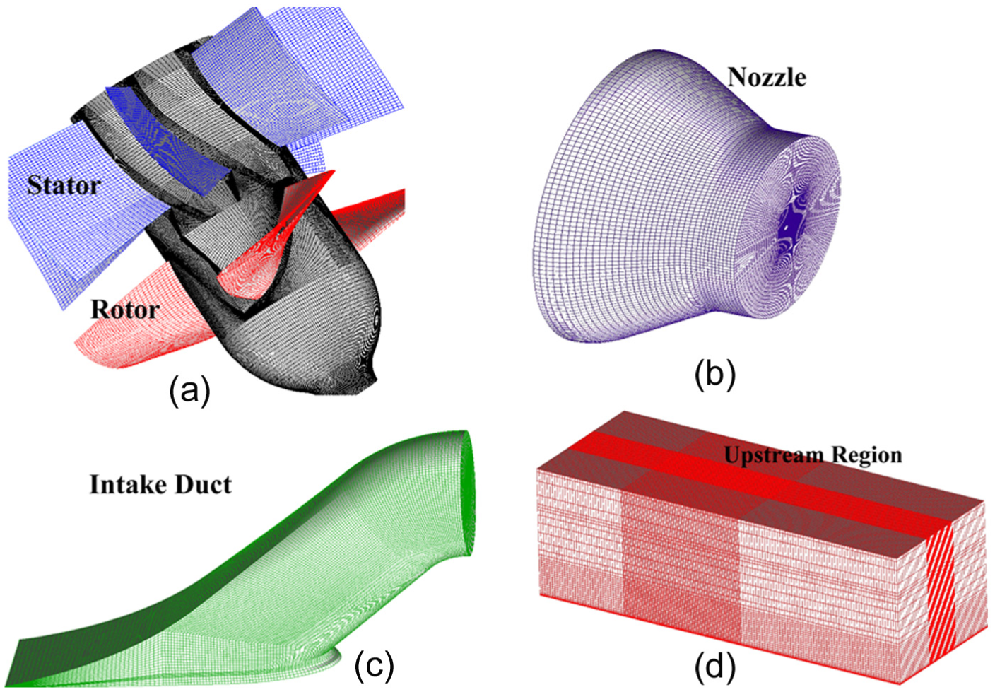
3D view of multi-block grid in the water-jet propulsion system: (a) rotor and stator, (b) nozzle, (c) intake duct, and (d) upstream region.

Grid independency analysis at the design point—normalized pump head.
As seen in the vessel frame of reference, the upstream region was set as a stationary frame, but the side and lower walls of the domain below the hull were set as relative motion (30 knots). The trim angle of the hull was fixed at 0 (even keel). The intake duct domain was also set as a stationary frame, in which the penetrating shaft was set as relative rotation (1450 r/min). The impeller domain was set as the rotating frame with design shaft speed of 1450 r/min. The guide vane and nozzle were set as a stationary frame. Furthermore, the interface between the stationary frame and the rotating frame was set as the rotor–stator interface, where frozen rotor method was used for the frame change.
The turbulent flow was solved by the re-normalization group (RNG) k − ε model, and the accuracy has been confirmed by Chang and Wang. 14 As shown in Figure 1, the outlet boundary condition of the nozzle was set as opening, and the outlet boundary condition of the upstream region was set as an average static pressure condition. The inlet boundary condition was set as a velocity normal to the inlet, and the initial velocity distribution was determined by equation (1). The actual inlet velocity was related to the ship speed and considered the velocity gradient by the boundary layer below the hull. The boundary layer thickness was calculated by Wieghardt equation.10,12 All the physical walls were set as nonslip walls
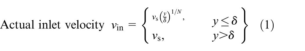

where vs is the ship speed, y is the depth normal to hull bottom, and Re is the Reynolds number based on the wetted length xw. In the complete water-jet propulsion system, Reynolds number is about 2.02 × 10⁸ which justifies the power law exponent N = 9 and the constant C = 0.27.
By changing ship speed, the steady-state simulations of the complete water-jet propulsion system were carried out and then the pump performances under the non-uniform inflow were obtained. The major performance of the water-jet pump is characterized by the head curves versus the flow rate. In detail, the flow rate was calculated at the outlet of the nozzle. Moreover, pump head was calculated based on the total pressure difference between the nozzle outlet and the pump inlet section. This simulated head contained hydraulic losses in the nozzle, but losses in the intake duct were excluded.
During the steady calculation, the high-resolution scheme was used for the convection terms, while the central difference scheme used for the diffusion terms. The convergence precision was based on reducing the maximum of the normalized residuals of the momentum and continuity equations to less than 10−5.
Configuration, grid, and boundary conditions of the single water-jet pump
The computation zone of the single water-jet pump was divided into four parts. Compared with the water-jet propulsion system, the nozzle, guide vane diffuser, and impeller were unchanged. However, the length of straight pipe upstream increases up to 2.5D2. This increase is able to keep the suction flow uniform under conditions.
The same multi-block grids of the water-jet pump were used in this steady simulation. Meanwhile, most numerical settings were remained, and the major change occurred in the boundary conditions. The average total pressure was imposed as an inlet boundary condition of the single pump, and the outlet boundary condition was set as the mass flow rate in accordance with the numerical result of the propulsion system. By changing the mass flow rate, pump performances under the uniform inflow were achieved. In detail, the pump head was calculated between the same sections.
Experimental setup
The experimental investigation of pump performances under the uniform suction flow was undertaken in a closed test loop facility. As shown in Figure 4, the single water-jet pump is located downstream of a flow straightener with two honeycombs. The honeycombs can improve the uniformity of the suction flow and reduce its scale of the turbulence. 15 The shaft penetrates into the inlet pipe and passes through the flow straightener to transmit torque from the motor to the tested pump. The AC motor provides power for the tested pump instead of the diesel engine because the motor possesses better control precision in the test shaft speed (1450 r/min) than the diesel. A special flange connects the discharge nozzle with the outlet pipe, whose inner diameter is 450 mm. Meanwhile, the inner diameter of the inlet pipe is also 450 mm.
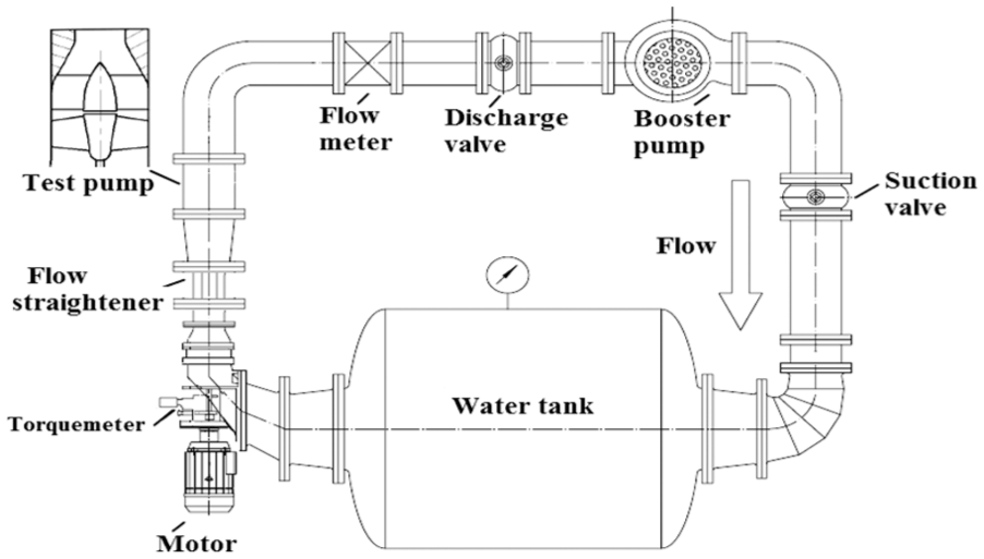
Sketch of the experimental setup.
In the measurement, a water tank with large water storage capacity made the flow and water temperature steady. Flow rates were obtained by a turbine flow meter with an accuracy of ±0.2%. The shaft power was measured by a torque meter installed on the shaft with a precision lower than 0.5%. The pump head was measured using pressure transducers located in the pump inlet section and the section immediately downstream of the nozzle discharge section. In particular, the measured head includes hydraulic losses in the nozzle, and the experimental uncertainty error of the head is below 0.5%.
Numerical results
Performance curves validation
In order to validate the accuracy of the current numerical method, Figure 5(a) compares the experimental curve of Q–H with the numerical data under the uniform suction flow. As a result, the predicted head tendency at flow rate Q/Qd = 0.85–1.1 presents a desirable agreement with the experimental curve. At the design flow rate, the prediction error is below 1%. The maximum error is 2.76% at a large flow rate, due to an increase in the leakage flow rate.
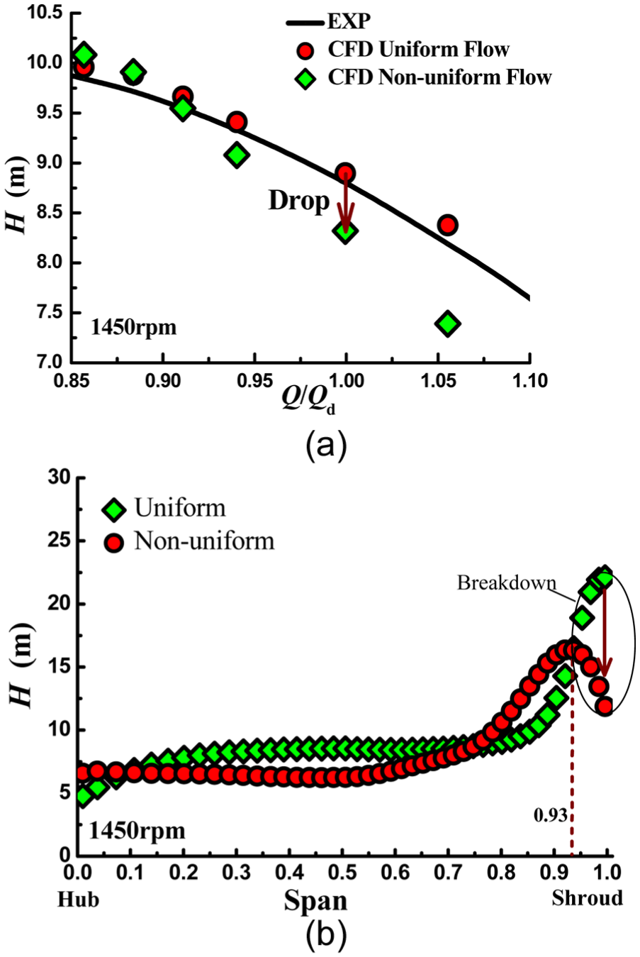
Comparisons of the pump head: (a) Q–H curves obtained from the experiment and numerical simulation and (b) pitch-average and spanwise distribution of the head at the design point.
Head breakdown of a water-jet pump under non-uniform suction flow
The actual pump performances cannot be directly measured in the water-jet propulsion system either installed in the towing tank or in the actual vessel. Therefore, the numerical method is generally utilized to calculate pump performances under non-uniform suction flow. Corresponding results are listed in Table 2. Although the ship speed changes from 12 to 36 knots, the flow rate only varies in the range of Q/Qd = 0.85–1.1. At the design ship speed, the flow rate is approximately equal to Qd. But the head is 8.32 m, smaller than the design value.
Numerical performances of the water-jet pump under non-uniform suction flow, at the design shaft speed (1450 r/min).

The head curve under the non-uniform suction flow is also plotted in Figure 5(a). As evident from the comparison, the non-uniform suction flow is unfavorable for the pump head in the concern conditions. At the design point, a drop in pump head is as much as 6.5% with respect to the uniform suction flow.
From a theoretical point of view, Euler formula states pump head in relation to circulation difference between the impeller entrance and exit. 11 Pitch-averaged circulations are calculated with CFD at the design point and then the spanwise distribution of the head is achieved
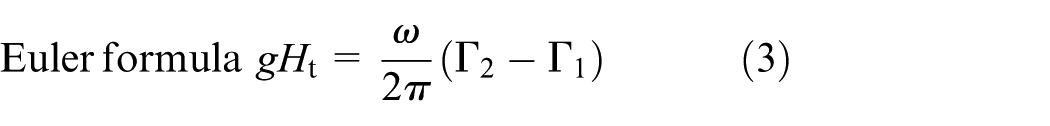
where Ht is the theoretical head, ω is the angular speed, and Γ1 and Γ2 represent the circulation at the impeller exit and entrance, respectively. It is known to all that span denotes dimensionless spanwise location along the blade, 0 is hub, and 1 is shroud.
Figure 5(b) reports the comparison of the spanwise distribution of pump head between the non-uniform and uniform suction flows. As obvious from the comparison, the non-uniform curve rapidly reduces instead of increasing from 93% span to the shroud. In contrast, the curve difference is slight from the hub to 93% span. Hence, this head breakdown near the shroud is responsible for the previous head drop at the design point. This fact confirms that the non-uniform suction flow exerts an unfavorable influence on the pump head, where the shroud region is more considerable.
As for the non-uniform suction flow, Bulten 7 also defined a variable ζ to quantify the level of non-uniformity. At the design point, the non-uniformity in the pump inlet section is about 0.393, while the value calculated at the same section under uniform inlet condition is only 0.023

where vx is the local axial velocity, vp is the mean axial velocity of the pump section, and Q is the volume flow rate.
Besides higher non-uniformity than uniform suction flow, non-uniform suction flow presents an asymmetric velocity profile in the pump inlet section, as illustrated in Figure 6. The dominant features are a velocity deficit at the top of the inlet section, a surplus at the bottom, and relatively large radial distortion throughout the sides with respect to the uniform suction flow. This velocity distribution resulting from boundary layer fluid ingestion combined the rotating shaft and an S-shaped duct, especially the ramp radius (1500 mm), bending radius (850 mm), and the inlet angle (i.e. 35° bending angle). In detail, high-velocity particles near the bottom are acted upon by a larger centrifugal force than the slow particles near the top do. 12 For this reason, these radii and bending angle also generate a transverse pressure gradient perpendicular to the main flow direction between the bottom and top.

Comparisons of velocity and pressure profiles between non-uniform suction flow and the uniform at the pump inlet section, at the design point.
As these asymmetric distributions are imposed on the water-jet pump, it is considered that different sectors or channels of the impeller operate at different flow conditions, which implies their working on different off-design points of the Q–H curve. In the torus from 93% span to the shroud, the bottom sector with high velocity corresponds to a large flow rate condition of the Q–H curve, denoted by red point in Figure 7. The larger the operating flow rate, the greater is the relative flow angle and the lower are the attack angle and the pump head. On the contrary, the top sector with low velocity corresponds to a small flow rate condition of the Q–H curve, denoted by blue point in Figure 7. Small flow rate requires small relative flow angle and large incidence which induces boundary layer separation on the SS. When the incidence angle exceeds the critical value, stall occurs in the blade shroud and then gives rise to a drop of the pump head. From a theoretical point of analysis, both sectors are responsible for the head breakdown near the shroud.

Incidence and flow separations at different flow rates.
Figure 8(a) compares the non-uniform and uniform inflow pitch-averaged velocity curves obtained with CFD at the design point. Non-uniform suction flow impacts the spanwise distribution of meridional velocity at the impeller entrance. When span is greater than 80%, the non-uniform curve is lower than the uniform. It means that non-uniform suction flow eventually causes a flow rate deficit in the torus from 80% span to the shroud although a velocity deficit and surplus individually emerge near the top and bottom. Namely, average operating point in this torus is comparable to a small flow rate condition, and the top sector with low velocity gives more contributions to the head breakdown near the shroud than the bottom sector. As indicated in Figure 8(b), the non-uniform suction flow also degrades the relative flow angle near the shroud, which provides strong corroborating evidence for the dominant role of the top sector in the head breakdown. Judging from the velocity triangle at the impeller entrance, the drop in the relative flow angle requires an increase in the positive incidence angle, which results in a possible boundary layer separation on the SS. As a consequence, partial stall is bounded to occur near the blade shroud downstream of the top sector at the design point and gives rise to the head breakdown under the non-uniform suction flow.

Pitch-averaged, spanwise distributions at the impeller entrance, at the design point: (a) meridional velocity, (b) relative flow angle, and (c) velocity triangles (v1 is uniform and
Discussion
Figure 9(a) plots a 2D view of the rotating stall. This sketch points out that the distinct separation on the SS and stall cells are the major flow features of the rotating stall. In fact, stall cells can be identified as the flow distortion upstream of the impeller. In addition, the head drop in the stall is associated with the pressure difference across the blade. 16 Therefore, the following discussion is emphasized on the distortion, separation, and blade loading to reveal the generation mechanism of the head breakdown under the non-uniform inflow. At the same time, the mechanism research is dedicated to the design flow rate. Because the cavitation and stall cells generally disappear at the design point, and exert slight influences on the the head breakdown with respect to the nonuniform suction flow. Namely, all the distortions and separations found in the following analysis are just resulting from the non-uniform suction flow.

Stall: (a) 2D sketch and (b) upstream circumferential distortion, near the top wall in the water-jet propulsion system, at the design point (contour surface with Qc = 40,000 s−2).
Top circumferential distortion upstream of the impeller shroud
To gain a better insight into the flow field upstream of the impeller which is disturbed by the non-uniform inflow, the second invariant of the velocity gradient tensor, Qc, is utilized. 17 Qc was written by CFX Expression Language (CEL) and embedded in the numerical calculation of the water-jet propulsion system. At the design point, a circumferential distortion is generated on the top wall upstream of the impeller shroud. As seen in Figure 9(b), this distortion is identified by the iso-surface with Qc = 40,000 s−2 and colored by purple

where
Figure 10 further describes the origination and development of the circumferential distortion. Owing to the high adverse pressure gradient on the top sector, low-velocity particles (see Figure 6) stagnate and separate upstream of the impeller shroud. Considering the interaction with the rotating impeller, the separation fluid deflects along the annulus instead of directly flowing downstream to the impeller. Eventually, separation flow rolls into a circumferential distortion upstream of the impeller shroud. In addition to general stall cell, the circumferential distortion disturbs the inlet velocity field, as reported in Figure 8. However, this distortion does not rotate at some percent of shaft speed in the absolute stationary frame. Because of the unchanged geometrical parameters of the intake duct, the asymmetric velocity profile in the pump inlet section slightly changes. Hence, low-velocity fluid still gathers and separates near the top wall. This fixed separation makes the circumferential distortion remain locked on the top wall upstream of the impeller shroud. It is concluded that the nature of the non-uniform suction flow is a locked circumferential distortion resulting in partial stall near the blade shroud downstream of the top sector.

Circumferential distortion locked on the top wall upstream of the impeller shroud: (a) front view and (b) side view.
As shown in Figure 10(b), the circumferential distortion is located in the sector region 2 and spans from 80% span to the shroud. Although all the blades rotate at 1450 r/min, every blade rotating through sector 2 is named as blade 2. Then, the shroud region of the blade 2 is chosen as the major study object in the following analysis of the boundary layer separation and its evolution because partial stall and its associated head drop occur in the shroud region downstream of the top of sector 2.
Flow model for a concentrated separation vortex
The distorted flow upstream of the shroud gives rise to a boundary layer separation on the SS, as demonstrated in Figure 11. The limiting streamlines on the SS, obtained with CFD at the design point, are given for both uniform and non-uniform suction flows. From comparison, a distinct converging line, that is, a separation line depending on Lighthill’s 18 separation criterion, emerges near the leading edge under the non-uniform suction flow. Namely, a local separation is corroborated to occur on the SS of the blade 2 due to a high incidence angle.

Comparison of limiting streamlines between the non-uniform (left) and uniform suction flows (right), on the suction surface of the blade 2, at the design point.
It is also noticed that a concentrated separation vortex (CSV) originates from the previous local separation on the SS and travels along the blade shroud. In Figure 12(a), the local separation gives rise to shedding of vortex lines from the SS and roll up adjacent fluid into a CSV. As traveling in the streamwise direction, the CSV seems to still maintain the vortical structure, but its vorticity gradually attenuates. Meanwhile, Figure 12(b) also illustrates an obvious decay in the swirling strength of the CSV in the outlet part of the blade 2. The swirling strength contours were drawn in seven sections (A–G), which were selected within the blade passage close to the casing wall. In each section, the maximum swirling strength point is obviously presented by a white ball, which is approximately regarded as the vortex core of the CSV in the section. 19 Vortex cores in different sections were connected into a core line of the CSV. Accordingly, the core line illustrated in Figure 13(a) reveals the trajectory of the CSV in the channel composed of the blades 2 and 3. The closer to the trailing edge the CSV approaches, the larger the circumferential distance between the vortex core and the SS. Furthermore, fluid rolled-up around the CSV also moves away from the blade 2 and migrates toward the adjacent PS of the blade 3 (Figure 13(b)). This behavior of the CSV is similar to pressure-side horseshoe vortex displacing from PS to the adjacent SS in turbine cascades.
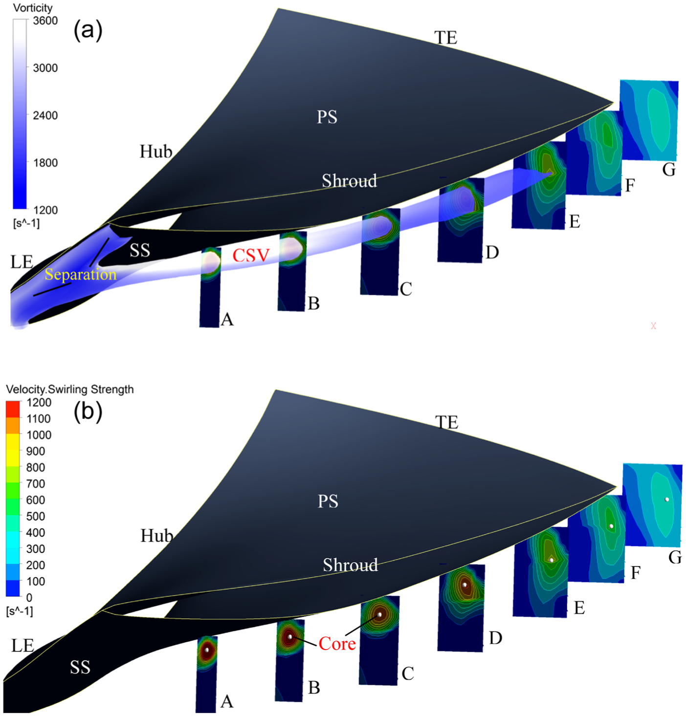
Concentrated separation vortex occurs on the suction surface of the blade 2, at the design point: (a) CSV is identified by iso-surface (Qc = 923,000 s−2) and colored with vorticity magnitude and (b) swirling strength contours at Sections A–G.

Concentrated separation vortex moves away from the suction surface of blade 2, at design point: (a) CSV trajectory, (b) rolled-up flow, and (c) streamlines at 95% span.
In the stream surface of an axial-flow pump, components of the Coriolis force and rotating centrifugal force are equal to zero, so the equilibrium of forces perpendicular to the streamline is about the pressure force and centrifugal force induced by streamline curvature 20

where p is the static pressure, w is the relative velocity, and rsm is the curvature radius of streamline. Effects of gravity, heat thermal, and viscous force are negligible in this equation.
Figure 13(c) exhibits streamline distributions in the blade to blade plane (i.e. stream surface) at 95% span. Near the SS of the blade 2, streamlines are deviated from the ideal direction and even inversion. For this reason, the reduced streamline curvatures trigger a lack of the centrifugal force and further result in a relative high pressure on the SS of the blade 2.20,21
Influence of the CSV on the blade loading
Figure 14 shows blade pressure distributions in the shroud section, at the design point, under non-uniform suction flow. It is noted that the CSV actually changes the pressure distribution of the blade 2, where the SS is more pronounced. In detail, the deviating CSV produces a considerable pressure rise over the entire blade shroud owing to the lack of centrifugal force. On the PS of the blade 2, its pressure level is consistent with that of the blades 1 and 3. As a result, the CSV causes a rapid drop in the pressure difference across the blade 2, that is, an obvious decrease in blade loading near the shroud. This is because the pressure difference across the blade is directly related to the blade loading, normalized with respect to the value

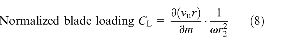
where vur relates to the blade circulation (Γ = 2πvur), and its meridional derivative is the blade loading. p+ and p− correspond to static pressure on the PS and SS of blade, respectively. m is dimensionless meridional distance, 0 is the inlet, and 1 is the outlet. zR is the impeller blade number, ρ is the medium density, and

Blade pressure distributions in the shroud section, at design point, under non-uniform suction flow.
Figure 15 depicts distributions of normalized blade loading in the shroud section, at the design point. The blade 1 or 3 has a similar blade loading level with respect to the uniform, while the blade 2 presents a substantial reduction in the blade loading near the shroud. Based on the vortex theory, bound vortices are distributed in the impeller, which make a blade circulation (lift force). 24 The local separation near the leading edge destroys bound vortices of the blade 2 and then vortex lines are released from the SS to degrade the blade circulation. As a result, the CSV induced by top circumferential distortion degrades blade loading in the shroud section and further triggers a remarkable drop in the pump head.

Normalized loading distributions in the shroud section, at design point, under non-uniform inflow: (a) comparison of CL between blades 1, 3 and the uniform and (b) comparison of CL between blades 1, 3 and blade 2.
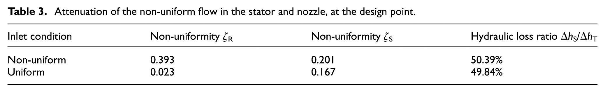
Comparable to the compressor of a turbine engine, 25 the non-uniform flow attenuates downstream of the pump impeller in the water-jet propulsion. As listed in Table 3, the non-uniformity in the stator inlet section (ζS) reduces to 0.201 under non-uniform suction flow and exerts less influence on the stator. In contrast, rotor–stator interaction increases ζS up to 0.167 under uniform suction flow; the similar non-uniformity produces similar hydraulic loss ratio in the stator. In other words, the CSV increases the non-uniformity of the flow forward to the stator, but the hydrodynamic performance of stator changes slightly with respect to the uniform. As for the behavior and development of the CSV in the stator, it will be investigated in further study. In conclusion, the results achieved in this study indicate that the CSV on the SS of the blade 2 is a major reason for the head breakdown of a water-jet pump under the non-uniform suction flow.
Attenuation of the non-uniform flow in the stator and nozzle, at the design point.
Conclusion
At the design point, the CSV and its effect on the head were numerically investigated in a water-jet pump under the non-uniform inflow. The CSV was identified by the Q criterion, and its influence was simplified into variations of the pressure distribution and blade loading. Based on this study, the following conclusions can be drawn.
The non-uniform suction flow to a water-jet pump impairs the pump head, where the shroud region is more intense. At the design point, the spanwise distribution curve of pump head exhibits a head breakdown near the shroud. It is thought to be the main reason for a drop in the global head of 6.5%.
As for the non-uniform suction flow, the pump inlet section presents a velocity gradient between the top and bottom walls. Due to interaction with the rotating impeller, low-velocity fluid near the top wall separates and evolves into a circumferential distortion. This distortion is taken as the nature of the non-uniform inflow, which remains locked and disturbs the blade shroud downstream of the top sector.
According to flow features in the case of stall, a physical explanation is given for the generation mechanism of the head breakdown under the non-uniform suction flow. Especially, a CSV on the SS is the key to this mechanism. In detail, the circumferential distortion changes the inlet velocity field on the blade shroud and then induces a local separation on the SS. This separation gives rise to shedding of vorticity from SS and the consequent formation of the CSV. Then, the CSV gradually moves away from the SS with a consequent lack of centrifugal force. For this reason, the deviating CSV increases the static pressure on the SS of the blade shroud, which further leads to a substantial drop in the blade loading. Eventually, the reducing blade loading generates a head breakdown near the shroud.
Finally, we hope that the achieved results could provide a sufficient understanding of the behavior and role of the CSV in a water-jet pump under the non-uniform suction flow. The detailed interaction between the CSV and the stator leading edge will be discussed in the future.
Footnotes
Appendix 1
Academic Editor: Takahiro Tsukahara
Declaration of conflicting interests
The author(s) declared no potential conflicts of interest with respect to the research, authorship, and/or publication of this article.
Funding
The author(s) disclosed receipt of the following financial support for the research, authorship, and/or publication of this article: This study was financially supported by the Open Research Subject of Key Laboratory of Fluid and Power Machinery (Xihua University), Ministry of Education (szjj2015-018), the Natural Science Foundation of Jiangsu Province (BK20151342), the National Natural Science Foundation of China (No. 51409127), and the Priority Academic Program Development of Jiangsu Higher Education Institutions (PAPD).