
Abstract
Auto-body’s front end structure, such as bumper and crash box, has the vital function of protecting other components from damage during low-velocity collision; moreover, it should accomplish excellent lightweight effect under the insurance of crashworthiness. This article combined the two approaches of lightweight improvement that listed as using structural optimization and replacing original materials with high strength and high mass efficiency materials or employing reinforced materials to conduct the crashworthiness optimization of assembly of bumper, crash box, and front rail. The original materials of bumper, crash box, and front rail were replaced by aluminum alloy 6060, TRIP800, and DP800, respectively. Aluminum foam was filled in bumper to replace the original reinforced plate and also was filled in crash box to increase energy absorption. The comparisons were made between an optimal selection from the multiple materials designs and the single material design. During optimization, crashworthiness criteria were defined as constraint conditions, and response surface surrogate model and genetic algorithm with elite strategy were employed to solve mathematical model of minimum mass. In single material optimization, the result already achieved the energy absorption increased by 10.1%, the peak collision force and the crumple distance decreased by 11.1% and 12.6%, respectively, and the total mass decreased by 11.1%. As for multiple materials optimization, the results obtained further optimal values. It is found that foam-filled bumper can overcome the disadvantage of bumper mid-bending that causes bumper failure of load bearing, and foam filler has the interaction effect with crash box as well, through which it received a significant growth of energy absorption. The application of multiple materials design greatly expands the potential of crashworthiness and lightweight optimization.
Keywords
Introduction
Nowadays, frequently occurring vehicle collision accidents have become a serious threat to safety of both passengers and drivers. The crashworthiness performance of automobile is of great importance in vehicle safety design. Conventionally, crashworthiness always depends upon the strength of body structure which has the direct relation with the structure design, material thickness, material strength grade, and so on. It is an effective approach to thicken and upgrade material or to improve structural design. Front end structure of automobile, especially bumper and crash box, has the purpose of protecting auto-body and passengers. As for the front rail, the minor deflection is acceptable during low-speed collision because it also undertakes protection role. To enhance crashworthiness of these components, distributing more material or using more suitable material was adopted as the general method. However, upsizing thickness or upgrading material randomly may lead to low weight efficiency of the car body. According to the report from International Aluminum Institute, automobile weight loss is 10%, fuel consumption decreased by 8%, and emissions decreased by 4%. Nissan chief technology officer Nobuo Okubo also pointed out that a 10% drop in vehicle weight, and fuel consumption reduced by 8% to 10%. Generally, body-in-white (BIW) weight for the car weight is 30%–40%, so it is of great potential for BIW weight reduction. With the fuel energy shortage, the energy saving and lightweight design which can make vehicles more economical have become quite significant tendency. At present, there are two ways to reduce the vehicle body weight by optimizing design of materials. (1) Replacing iron or steel with low-density materials, such as carbon fiber, aluminum alloy (AA), or foam filler. (2) Using high-strength steel materials to reduce the thickness of plates.
As an auxiliary device of auto-body, bumper has begun to draw more and more attention for its lightweight design based on the lighter material selection. Wang and Li 1 conducted design and analysis of automotive carbon fiber composite bumper beam based on finite element analysis (FEA). Hu et al. 2 made a research on carbon fiber–reinforced plastic bumper beam subjected to low-speed frontal impact. Michael et al. 3 studied the expanded polypropylene foam energy management for bumper system. Concerning auto-body’s front end structure, Anindya et al. 4 presented the efficient design optimization of an automobile front end structure. Bryan et al. 5 investigated the mass efficiency of front crush box by simulation and physical test. Regard to lightweight application of high-performance material, Chen and Aleksy 6 discussed the influence of advanced high-strength steel (AHSS) part geometric features on crash behavior. Jacek and Ireneusz 7 put AHSS into use of automotive body parts and simulated its stamping process. Huang et al. 8 introduced AHSS to auto-roof strength application and studied by FEA simulation which demonstrated that AHSS design is capable of meeting the proposed more stringent roof crush requirement. Yang et al. 9 explored the dynamic behavior and energy absorption effects of an AA. As for theoretical research on aluminum foam, Deshpande and Fleck 10 proposed isotropic constitutive models for metallic foams. Veloso et al. 11 developed a numerical model to study the effects of aluminum foam filler on the dynamic behavior of a steel tubular energy absorber. Li et al. 12 presented the deformation and energy absorption of aluminum foam-filled tubes subjected to oblique loading. Matteo et al. 13 described the anti-intrusion bars made of aluminum foam-filled tubes for automotive use and compared dimensions and conditions of tested tubes based on the different materials as low carbon steel and high-strength steel. Attia et al. 14 implemented the nonlinear FEA of the crush behavior of functionally graded foam-filled columns. Ahmad et al. 15 investigated dynamic energy absorption characteristics of foam-filled conical tubes under oblique impact loading.
Using these alternative lightweight materials can make the auto-body lighter; generally speaking, the lighter the mass of the vehicle body, the worse the body strength and crashworthiness performance. Body structure optimization design can achieve lightweight, high stiffness, high strength, and crashworthiness. 16
To balance the contradictory design targets as lightweight and crashworthiness, the optimization study should be carried out in realizing lightweight design based on meeting the premise of crashworthiness. But structure optimization during the collision process, accompanied with geometric nonlinear, physical nonlinear, material nonlinear, and coupled with large deformation of the structure, is a typically dynamic and highly nonlinear optimization problem. 17 To solve this complicated crashworthy optimization problem, surrogate model is generally used. For instance, Sun et al. 18 optimized the crashworthiness for functionally graded foam-filled thin-walled structures using surrogate model, and the optimal results indicated that the functionally graded foam-filled structure is superior to the uniform foam-filled structure. Furthermore, Song et al. 19 conducted the crashworthiness optimization for foam-filled tapered thin-walled structure with multiple surrogate models, which are named polynomial response surface (PRS), kriging (KRG), radial basis function (RBF), and support vector regression (SVR), respectively. Acar et al. 20 also employed three kinds of surrogate models such as PRS, KRG, and RBF to complete multi-objective crashworthiness optimization of tapered tubes and evaluated the solving accuracy of PRS, KRG, and RBF. Besides, Kim et al. 21 put forward the equivalent static load method to solve optimization problems of collisions in recent years, which established static linear optimization model for each time step of collision explicit dynamic analysis, and used the sequence optimization method to solve dynamic collision problems.
In this article, the research object integrated the bumper, the crash box, and the front rail which influenced the performance of front end structure greatly in low-velocity frontal impact. Taking this assembly as an example, traditional lightweight size optimization, as first step, was conducted using single material of mild steel during collision process. And then multi-materials of AA, AHSS, and aluminum foam were employed to bumper, crash box and front rail, and bumper filler and crash box filler, respectively. The collision performance results were compared under the same condition. The optimal design was also selected based on the performance assessment. Next, crashworthiness and lightweight optimization which considered seven variables were implemented synchronously with regard to multi-material design above. Finally, comparison was made between size optimization of single material and size optimization of combined structural design based on multiple materials.
Crashworthiness optimization design
Owing to the nonlinearity during the collision process, it is very difficult to perform sensitivity analysis to obtain gradient information for crashworthiness optimization. If using the parameter automatic iterative optimization method, each parameter iteration needs a simulation calculation, and thousands of iteration steps in optimization seriously limited this method.
However, using surrogate model method can transform the complicated collision optimization problem with high nonlinearity to an easier approximate model optimization. The procedure is as follows: first, taking samples by design of experiment (DOE), calculating test values by nonlinear explicit dynamic code LS-DYNA, establishing the approximate model, and finally, optimizing the response surface to get the optimal solution using genetic algorithm with elite strategy (GA-ES). The flow chart of optimization is shown in Figure 1.

Flow chart of crashworthiness optimization.
Description of object structure
Figure 2(a) describes the research object of this article. During vehicle low-velocity frontal collision, this object is an important structure for vehicle front end energy absorption and occupants protection, and it contains the bumper, the reinforced plate behind the bumper, crash box inner part and crash box outer part, front rail inner part and front rail outer part, the fixed plate which fixes the end constraint of the front rail, and the connection plate which connects front rail and crash box. Besides, for improved design, there are several blocks of foam filler inside the bumper and crash box. For the reason of weight efficiency, the reinforced plate may be removed. The moving rigid barrier loading velocity is 20 km/h which is suitable to simulate the low-velocity collision.

Front end structure of automobile: (a) components of study object and (b) force flow diagram.
When vehicle is in frontal collision, the reasonable energy transfer path should be that the bumper distributed the energy to crash boxes both at left and right, which makes compressive deformation of crash box, so the “force flow” can be transferred to front rail though the connection plate, as shown in Figure 2(b). If the collision kinetic energy is less than the energy absorption limit of the crash box, the front rail is protected well; otherwise, the front rail will be damaged by large deflection and accompanied with a large collision force transferred to the passenger compartment. After the low-speed collision, the replacement costs of bumper or crash box are relative low, but the repairment cost of front rail is very high. The ideal front end structure should protect front rail from large deformation after crash box is crushed, while front rail should avoid oversize lateral bending or instability in the deflection, which lead to a sharp crumple of front structure and an intrusion into occupants’ residual space. The compressive deformation of front rail should be along the axial direction as much as possible.
Structural crashworthiness criteria
Basically, it is of importance to define crashworthiness criteria with regard to optimizing the performance of foam-filled assembly as predesigned bumper, crash box, and front rail. To date, many indicators have been established to evaluate the crashworthiness of energy absorption capability.20,22 Among these indicators, specific energy absorption (SEA) and crush force efficiency (CFE) can systematically describe the capacity of energy absorption and have been widely used for structure design and optimization problem to crashworthiness and lightweight. However, excellent energy absorption and buffer ability cannot guarantee that the crumple distance satisfied safety requirements. And the large crumple distance is difficult to ensure a good residual space for passengers. Therefore, in this study, longitudinal structural crumple distance was introduced as the third indicator to evaluate cab’s risk of intrusion derived from the maximum deformation of the assembly. In another word, crumple distance contributes to the elimination of abnormal crumple samples produced by bending of front rail. In abnormal bending condition, the crumple value is larger than normal value (L > C), as shown in Figure 3. The elimination of these improper samples ensures the accuracy of the surrogate model.

Crumple distance conditions.
Commonly, the energy absorption (EA) of automobile components measures capacity of energy absorbing during the impact process, which could be determined mathematically as
where
SEA reflects the energy absorbed per unit mass for a single ith part as

For the whole structure with part number of j, SEA could be written as
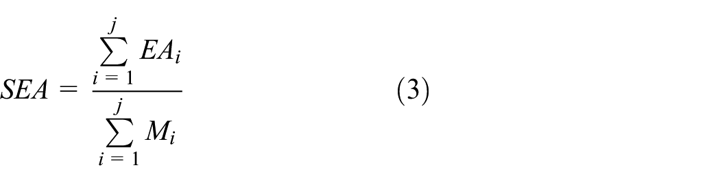
where
The mean crash force

CFE is constructed as

For a single ith part, mean crash force and CFE are as follows


Longitudinal structural crumple distance L is equal to deformation displacement

All of the indexes above can be read from calculating date by LS-PREPOST, which is the post-processing software of LS-DYNA.
Material property
AHSS
According to the ultra lightweight steel vehicle research by Ultra Light Steel Auto Body-Advanced Vehicle Concepts (ULSAB-AVC), high strength steel is defined as the yield strength in the range of 210–550 N/mm2, the yield strength of over 550 N/mm2. On the basis of the different strengthening mechanisms, the high-strength steel is divided into ordinary high-strength steel and AHSS. Among them, ordinary high-strength steel mainly includes high-strength interstitial-free (IF) steel, bake hardening (BH) steel, isotropic (ISO) steel, carbon–manganese (CMn) steel, and high-strength low-alloy (HSLA) steel. AHSS mainly comprises dual phase (DP) steel, multiphase (CP) steel, transformation-induced plasticity (TRIP) steel, bainite (BP) steel, and martensitic (MART) steel. The map of Figure 4 shows the relationship between strength and plasticity of all kinds of high-strength steel sheets. From the map, with an increase in the strength, the plasticity significantly decreased. Although the plasticity decreases with an increase in strength, the extent of decrease in plasticity is different because of the different strengthening mechanism. The colligate character that combined high strength and excellent plasticity can be achieved using structure strengthening, such as TRIP and DP. BIW parts require high strength and excellent plasticity because of crashworthiness and lightweight requirement. With better stress distribution character, higher strain harden property, more remarkable crashworthiness performance, AHSS have become a very promising choice in material design and optimization for BIW or parts for thickness decrease.

Mild steel and AHSS constitutive model
The analysis of the assembly, consisting of bumper, crash box, and front rail which were made of mild steel or AHSS and AA, was implemented in LS-DYNA to simulate its dynamic impact process. Figures 5–7 illustrate the true stress versus true plastic curve of mild steel, DP800, and TRIP800, respectively. To numerically characterize the material behavior, the constitutive equation for the effective yield stress as a function

where

True stress versus true plastic strain curve of mild steel. 25

True stress versus plastic strain curves at different strain rates for DP800 high-strength steel. 26

True stress versus true plastic strain curve of Trip 800 high-strength steel. 27
Material property parameters of DP800.

Aluminum alloy (AA6060T4) constitutive model
Owing to lower density, higher strength ratio, and better energy absorption, AA has become a promising material in automotive lightweight application. In this study, AA6060T4 was selected with the mechanical property in Table 2: Young’s modulus E = 68.2 GPa, initial yield stress

Material property parameters of AA6060T4.


Engineering stress–strain curve of AA6060T4. 30
Consequently, calculated result of 106 MPa is the actual stress value of AA6060T4.
Aluminum foam constitutive model
As a kind of filler material, aluminum foam was simulated well by type 154 material in LS-DYNA based on the model proposed by Deshpande and Fleck, in which the yield stress function

where Y represents the yield strength and the equivalent stress

where

The strain hardening rule is employed as

where

The densification strain

where
Constants
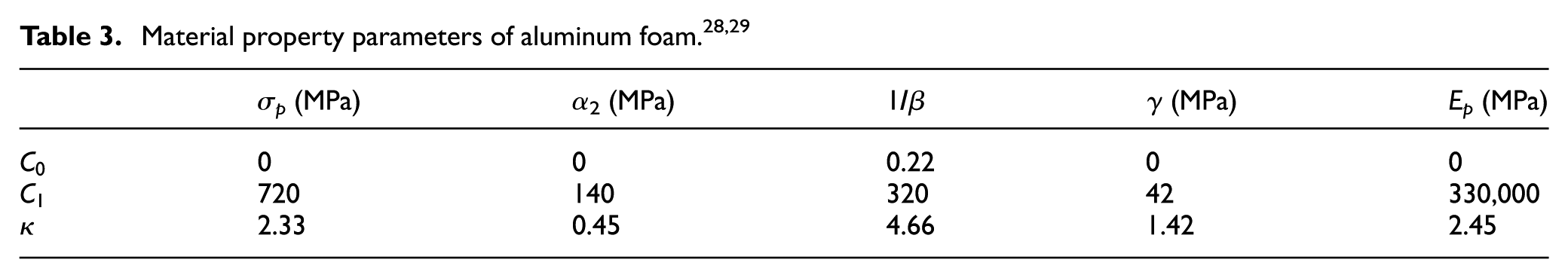

Engineering stress–strain curve of aluminum foam with different densities. 31
Finite element method numerical modeling of foam-filled structure
Figure 10 shows the structure modeling method. At present, the simulation mostly was implemented by LS-DYNA, a nonlinear finite element code which is specialized in solving dynamic impact problem. The bumper and crash box are similar to thin-walled parts and can be modeled by quadrilateral Belytschko-Tsay shell elements precisely with five integration points through the thickness to simulate the buckling response. The foam filler either in bumper or in crash box was simulated by eight-node solid elements with reduced integration and hourglass control. Node-to-surface contact algorithm was employed between foam filler and its surrounding material. The constitutive model of foam is type 154 as mentioned above, while other parts adopted type 24 to model piecewise linear plasticity material character.
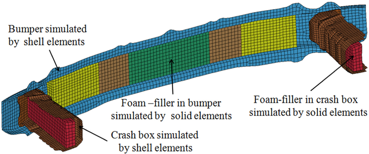
Finite element modeling of foam-filled structure.
Comparison of performance analysis
The use of AA, AHSS, and aluminum foam constitutes the updates of the original material and structure design. To discuss the influences of bumper, crash box, and front rail on energy absorption and deformation process based on these updates, five groups of contrast tests were designed and are as follows: (a) using mild steel material for all parts; (b) replacing the bumper material with AA, while other parts with AHSS; (c) adding foam filler in bumper and crash box based on Design b; (d) removing the reinforced plate based on the Design c; (e) subtracting foam filler based on Design d. To discuss the influence of materials, among these five designs, all differences merely existed in material selection and structure design, while the parts thickness and foam densities kept the same value. So, they can be considered as qualitative tests.
Figure 11 shows the deformation of assembly and enlargement of crushed crash box. Both Design c and Design d have flat and straight bumper shapes, with excellent axial compression performance of crash box.

Deformation of assembly and enlargement of crushed crash box: (a) mild steel (all parts), (b) AA (bumper) AHSS (other parts), (c) AA (bumper) AHSS (other parts) with foam, (d) AA (bumper) AHSS (other parts) with foam without reinforced plate, and (e) AA (bumper) AHSS (other parts) without foam without reinforced plate.
Comparison results and analysis
To obtain statistical analysis results, Table 4 numerically describes the diversity of performance as bumper, crash box, and front rail according to different designs. In the table, symbol “+” denotes “with” while “−” denotes “without.” From Design a to Design e, the mass decreased in general trend except Design c for adding foam in both bumper and crash box comparing Design b, and Design d has a mass reduction because the reinforced plate was removed. The mass comparison of Design b and Design d indicates the mass increment of foam is less than that of reinforced plate. The function of foam is not only in form of energy absorption by itself but also in coupling with bumper and made bumper more effective in energy absorption. The crash box has a larger energy absorption if filled with foam because the foam contributes a large portion. Because the majority impact kinetic energy was absorbed by bumper and crash box, hence, front rail was protected in excellent condition barely with tiny deformation and little energy absorption. Axial stability during the deformation process can be considered as a verification of structural performance, and to this point, both Design c and Design d achieve excellent level, which are the results of bumper’s excellent effectiveness.
The diversity of performance based on different designs.

AA: aluminum alloy; AHSS: advanced high-strength steel.
In Design a, there is a result of lateral dilation of front rail with bad axial stability, and bumper bent in the central section vividly. In Design b, front rail improved, but the bumper was still bent largely if the previous material (mild steel) was replaced with AA and AHSS only. In Design c, after bumper and crash box were foam filled, the deformation became quite better with a very flat and straight bumper result. As an attempt to achieve better lightweight effect, the reinforced plate was removed in Design d, but the result was still in agreement with design c, and therefore, Design d has a higher mass efficiency. To verify the effect of foam filler, Design e subtracts the foam in bumper and crash box, and the result indicates that energy absorption declined instantaneously and bumper deflection turned up serious bending again, which demonstrate the necessity and importance of foam filler. Figure 12 expressed the variation trend to energy absorption and deformation based on the data from Design a to Design e.

Variation trend to energy absorption and deformation based on multiple designs: (a) the variation trend of energy absorption and (b) the variation trend of deformation.
The discussion about the results
Comparison results of five designs show that putting AHSS into use can significantly improve the structural stiffness and strength with the same thickness; therefore, it provides an approach to realize equal strength with lighter design; AA is a promising material in lightweight design and is a suitable choice for bumper; foam filling is a very effective measure for energy absorption, especially with foam having a unique role when coupled with bumper, it not only reflects in enhancing bumper stiffness for sustaining steady deflection but also come a long way for AA adaption in bumper design to resist mid-bending, which is very potential to exert the comprehensive capacity of whole assembly; owing to application of new design, original reinforced part may be replaced or removed which can obtain a better lightweight effect.
The interaction effect of foam filling
It can be seen that the foam-filled structure had a higher value of energy absorption than the sum of energy absorptions from the structure and foam separately; as plotted in Figure 13, the energy absorption curves of foam-filled bumper and foam-filled crash box showed a strengthening effect. The interaction effect, as painted areas in Figure 13, can be accounted for this phenomenon.
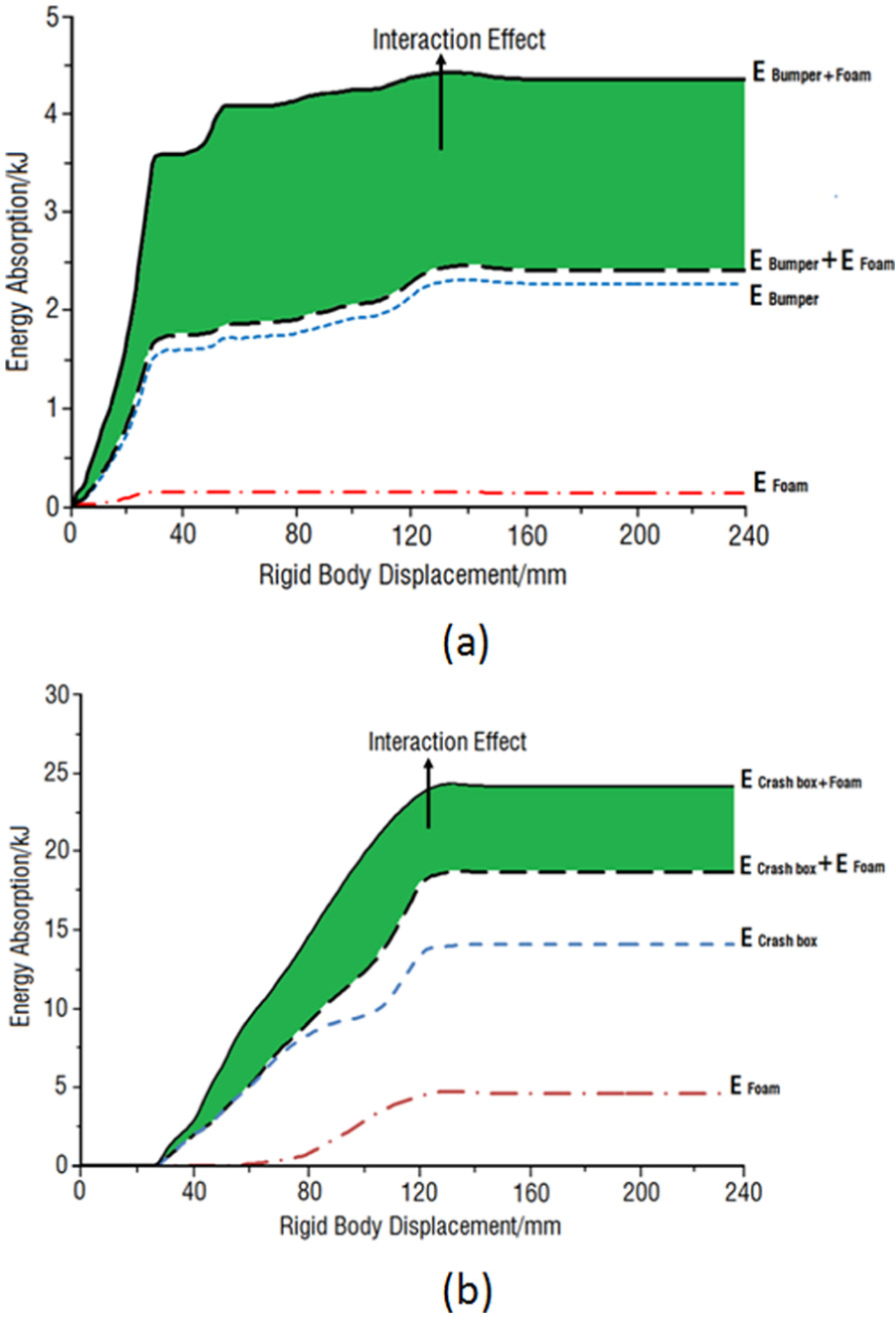
Interaction effect of energy absorption in foam-filled structures: (a) foam-filled bumper and (b) foam-filled crash box.
Comparing the strengthening effect of structures as bumper and crash box, bumper had an up to 80% increasing range which is larger than crash box with 29% increase. It can be explained as following reasons: the major role of bumper is to support load or to transfer force, meanwhile, with a minor function of energy absorbing, which is contrary to crash box, and it can be easily observed from the absolute value of energy absorption. What must be mentioned is bumper’s major role cannot perform well if a serious bending appears; therefore, improvement in energy absorption and elimination of bending condition are the processes contributed to coupling with foam filler.
The foam-filled crash box achieved extra strengthening effect by foam filling as well. As aimed to stand axial crush, foam-filled crash box is similar to foam-filled tube, and the strengthening effect was in agreement with former fundamental study subjected to the tube. 29
As for bumper, the strengthening mechanism has been listed above. Although it is not completely equal to crash box because the impact direction is not along axial, the conclusion can be drawn as foam filling in bumper or in crash box can significantly improve original performance and existence of interaction effect accounts for these improvements.
It can be found from Figure 13(a) that energy absorption of bumper had a sharp growth, while energy absorption of crash box has slightly raised before displacement of 40 mm; nearly beyond that point, the situation exchanged, that is, growth of the curve in Figure 13(a) gradually slowed down and finally reached a steady value. However, curve in Figure 13(b) increased as a certain slope-rate during displacement between 30 and 120 mm, after that the value was stable. The reason is the bumper’s major deflection occurred from 0 to 30 mm, and crash box involved in deflection after the deformation of 30 mm. This sequence validated the reasonability of deformation process which proved the foam-filled design with AA and AHSS is appropriate.
Optimization of single or multiple material(s) design
In original design, the assembly was built based on the mild steel which can be considered as single material design. After material upgrading and foam filling, the new design, that combined AA, AHSS, and aluminum foam, became a multiple material structure. The comparison analysis revealed that Design d is the optimal solution to both crashworthiness and lightweight. Hence, two rounds of optimization were conducted based on the structures and materials pattern like original design and Design d and corresponded to size optimization of single material and parameter optimization of multiple materials, respectively.
Components parameterization
The thickness dimensions of components and densities of foam were selected as optimization parameters. The parameter of each part in the assembly is shown in Figure 14, which are expressed as

Parameterization of components: (a) original design parameters, (b) merging, and (c) new design parameters.
Optimization of mathematical model
The purpose of the collision optimization in this article is to achieve a lightweight structure which satisfies the crashworthiness requirements at the same time. Therefore, the objective functions can be expressed as equation (17) for single material and equation (18) for multiple materials


To meet lightweight and crashworthiness synchronously in an optimization, the complicated multi-objective optimization is always employed. By considering the crashworthiness evaluation indicators such as energy absorption, peak collision force, and newly introduced crumple distance as the performance constraints of the optimization, this work successfully transformed the multi-objective optimization into single target. The ranges of thickness dimension to each part are the size constraints. With basis above, the constraints combining performance and size are shown in equation (19) for single material
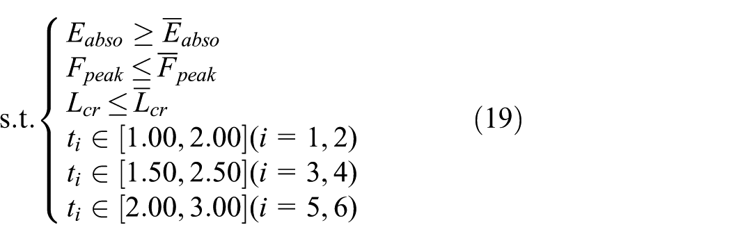
As for multiple materials, the ranges of densities were added to constraints and defined by equation (20)
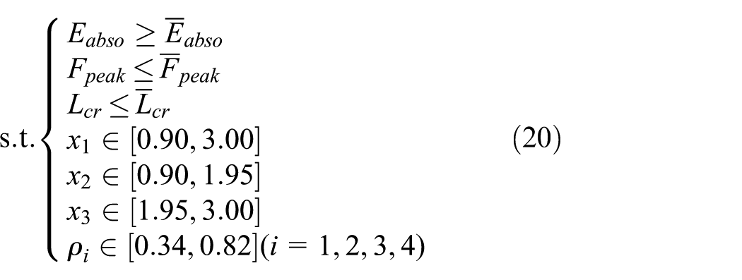
where
Improvement in design
Identification of the key experimental factor, determination of the best parameter combination, and construction of the approximation model are the major functions of DOE, which is quite necessary part in this article. DOE contains parameter test, central composite design, Box-Behnken design, orthogonal array, Latin hypercube, and so on. It is hoped that the test points are broadly representative in DOE. In orthogonal array, the levels and factors are well balanced, and the test points are homogeneously distributed, which can greatly reduce times of test analysis. Therefore, the orthogonal array is a kind of high efficiency, rapid, and economic design method.
The upper and lower interval bounds of

Deformation modes of improper samples.
As shown in Figure 16(a), the intervals of six design variables are divided into two groups which are used to generate orthogonal array 1 and orthogonal array 2 as different color zones shown. The low-segment group in dark (red) zone provides No. 1 to No. 25 tests, while the high-segment group in light (green) zone provides No. 26 to No. 50 tests. Adopting single material of mild steel as a consequence guaranteed that the upper interval bounds of

Definitions of variables’ sections: (a) single material and (b) multiple material.
As for multiple materials, condition varied because the stiffness is not exactly depending on the thickness. Comparing DP800 and TRIP800 components, AA6060 used in a thicker bumper is acceptable in stiffness, strength, and mass efficiency, but concerning the close strength characteristic between DP800 and TRIP800, it is reasonable to put crash box and front rail into low-segment group and high-segment group, respectively, as shown in Figure 16(b).
The improper results which are similar to Figure 15 are eliminated by improved composite orthogonal design, and the updated sample data are shown in Figure 16. The reasonable deformation sequence pattern is shown in Figure 17 which has an intact front rail before crash box is completely crushed. Obviously, the improvement in the DOE ensured the assembly structure follow the right deformed order. The deformation process of Figure 17 also proved validity and rationality of DOE sampling.

The reasonable deformation sequence.
Response surface method
The core of the response surface method is to estimate the objective function and the constraint function. In the form of basis function, the objective function is approximated as
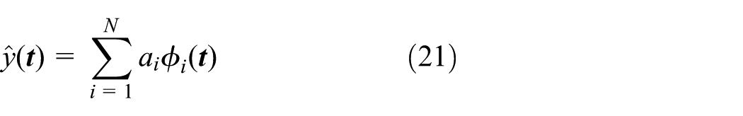
where
The principle of the basis function selection is satisfying high accuracy and fast convergence. To balance the solving precision and calculation, a quadratic polynomial is chosen as equation (22)

In order to obtain the unknown coefficient

It is necessary to note that objective vector consisted of objective function values which were calculated by LS-DYNA, and the response vector is from response function. The matrix below contains the values of the basis function estimated by the sample points

Substitute matrix (24) into equation (21) to establish the expression of
Composite orthogonal test points and corresponding results.
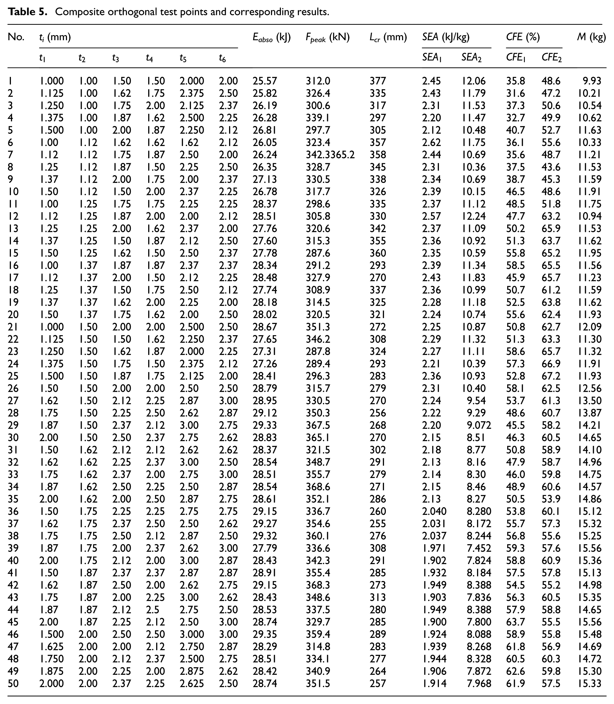
Table 6 presented the DOE of multiple material design, which contained three thickness and four densities. AA6060, TRIP800, and DP800 are employed to components represented by
The DOE of multiple material design.

DOE: design of experiment.
Table 7 was filled by the results corresponded to the DOE samples of multiple material design.
The results of the test points based on Table 6.

By putting all of data subjected to SEA and CFE of bumper and crash box together, Figure 18 further compared the values between single material design and multiple material design.
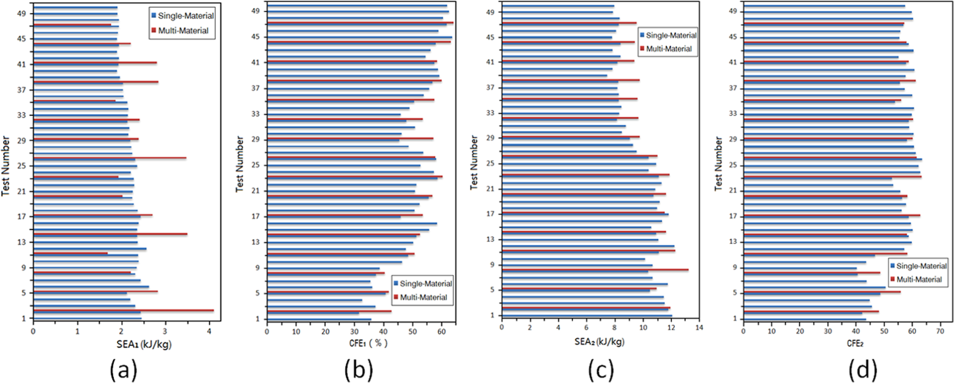
Comparison of SEA and CFE of bumper and crash box: (a, b) bumper and (c, d) crash box.
It can be observed a large SEA increases if single material is replaced with multiple materials, especially for bumper. The CFE roughly maintained the same level, and there is a slight improvement in bumper if using multiple material design.
Approximate model
There are relatively simple linear relationships between mass and variables. It is suitable to use first-order polynomial for fitting, and single material and multiple materials are expressed as equations (25) and (26), respectively


The relationship of the energy absorption, the peak collision force, the crumple distance, and the variables is nonlinear, so high-order polynomial fitting is used. To balance the accuracy and the number of items, both single material and multiple materials used quadratic polynomial, as equations (A.1)–(A.6) in Appendix 1.

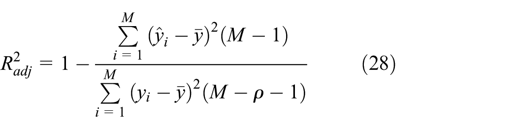
where in equations (27) and (28),
GA solving optimization model
GA is a kind of random search method based on the biological evolution which was first proposed by Professor J. Holland in University of Michigan. This article made some improvement based on the classic GA, that is using elitist strategy. The specific is to calculate the maximum fitness of each generation, which is retained as the optimal individual according to a certain probability. Only when the fitness of the optimal individual in the next generation is greater than that of the elitist individual in the last generation, there will be a replacement.
In this article, the penalty function methodology is employed to transfer the crashworthiness criteria to constraint conditions; equations (29)–(31) detailed the construction processes of penalty function
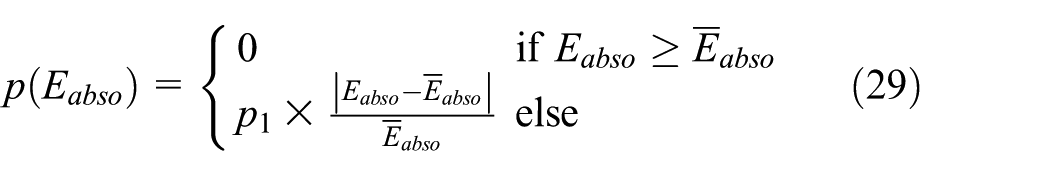

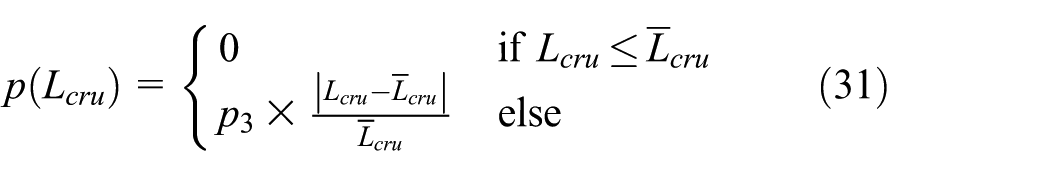
The basic idea is that the penalty function is equal to zero as long as the actual value satisfies the threshold; otherwise, the penalty function is multiplied with penalty coefficient. The penalty coefficients are set as 10,000
Equation (32) described the construction of fitness function subjected to objective function and penalty function

In solving procedure, Fitness was considered as the standard of satisfying the constraints. Figure 19 exhibited the solving process of GA-ES, and the blue line represents single material, while the red line stands for multiple materials. As the adoption of elitist strategy, all graphs had stable flat platforms and the values changed in the same iteration step. Fitness realized the steady-state maximum finally which indicates that every criterion has met the requirement and optimal mass value was achieved.

GA-ES iteration process.
Optimization results
Optimization results are shown in Table 8, in which different variables represented the diversified parts, and the thicknesses of four parts decrease after optimization of single material design, while seven variable values drop in multiple material optimization. In single material optimization, the result already achieved that the energy absorption increased by 10.1%, the peak collision force and the crumple distance decreased by 11.1% and 12.6%, respectively, and the total mass decreased by 11.1%. In multiple material optimization, the results tend to be further optimized.
Optimization results.

Conclusion
Concerning the low-velocity crash of passenger car, the front rail plays an important role so that must be integrated with bumper and crash box which have the function of protecting the other components including front rail from damage. Meanwhile, as the structural accessories of auto-body, bumper and crash box have the requirement of lightweight besides good crashworthiness. Lightweight and crashworthiness are contradictory targets in auto structural design; therefore, it is of great necessity to optimize their comprehensive performance of lightweight and crashworthiness based on the criteria such as energy absorption, peak collision force, and crumple distance.
In the process of size optimization in order to improve lightweight and crashworthiness performance, it is found that using multiple materials is of greater potential that especially reflected in AA has higher mass efficiency and AHSS has higher strength; moreover, aluminum foam is so promising for significant strengthen effect in both bumper and crash box. Besides what mentioned above, the following conclusions are summarized:
Energy absorption, peak collision force, and newly introduced crumple distance can systematically describe the optimization criteria; by considering these crashworthiness evaluation indicators as the performance constraints to optimization, the problem can be converted from multi-objective optimization to single-objective optimization.
Matching aluminum foam with AA and AHSS can improve the performance of original design and the foam-filled bumper resists mid-bending of original bumper, foam-filled crash box absorbed more impact energy. The foam-reinforced advantage is mainly reflected in its interaction effect of energy absorption.
After traditional size optimization, the mild steel structure with single material can accomplish 11.1% mass reduction, 10.1% energy absorption increase, 11.1% peak collision force decrease, and 12.6% crumple distance decrease. The multiple material optimization which employed AA, TRIP800, and DP800 to original structure and filled the aluminum foam in bumper and crash box obtained quite better optimization results compared to conventional single material optimization.
Footnotes
Appendix 1
The polynomial response surface surrogate model of energy absorption, peak collision force, and crumple distance are given as follows.
Equations (A.1)–(A.3) are for single material
Equations (A.4)–(A.6) are for multiple materials
Academic Editor: Filippo Berto
Declaration of conflicting interests
The author(s) declared no potential conflicts of interest with respect to the research, authorship, and/or publication of this article.
Funding
The author(s) disclosed receipt of the following financial support for the research, authorship, and/or publication of this article: This work was supported by NSFC (Natural Science Foundation of China) under grant no. 90920305, the Central University Fund Innovation Team Project under grant no. 2013G322402, and the Special Funds for Scientific Research Projects of Basic Business Expenses to Central University under grant nos 2013G5220007 and 310822161115.