
Abstract
If high-power machines are used and a large number of people are present, a significant amount of heat will be generated, which forms an upward thermal plume. The interaction problem occurs when the cold jet and the thermal plume meet. This article presents the interaction mechanism between a momentum source and a buoyancy source and deduces the interaction parameter β to investigate the effects of parameters such as the power of the source, the air-supply velocity, plume spacing, and nozzle spacing height. Experiments were carried out to investigate the flow field of the air jet affected by the plume and to validate the theoretical work.
Introduction
For an air-conditioning system in summer, in order to keep the indoor temperature, humidity, and air velocity within reasonable ranges, air must be handled and sent to the room in the form of a nonisothermal jet.1–3 If high-power machines are used and a large number of people are present, a significant amount of heat will be generated, which forms an upward thermal plume. The interaction occurs when the cold jet and the thermal plume meet.
When the surface temperature of the indoor heat sources, such as electronic components, heating equipment, and human beings, is higher than the indoor ambient temperature, rising hot air will be generated above the heat sources, named as thermal plume. 4 This is a common convective phenomenon, contributed by buoyancy force which also dominates the vertical motion and diffusion of thermal plumes.5–7
Zeldovich, 8 Batchelor, 9 and Morton et al. 10 laid the theory foundations to describe and explain the behavior of classical pure plume. The behavior of plumes in the mantle is likely to be complicated by effects such as the depth dependence of material properties, non-Newtonian viscosity, and phase changes. Various researchers have attempted to model some of these complex features experimentally11–13 and numerically,14–16 including the rising movement of the fire smoke changing over time and its heat transfer with the vertical wall in the closed shaft and the open staircase, including the effects of turbulent jet diffusion on flame length and trajectory.17–19
Currently, lateral air supply by nonisothermal air-jet nozzles is widely used in the indoor environment, which satisfies air-conditioning design requirements in the lower workspace depending on the jets. After preliminary study by our research group, 20 it can be found that the thermal plume rising vertically, the buoyancy force interfering horizontal jets, and the two-way motion between jets and plumes acting significantly with greater indoor heat power. From the previous study, it is also known that the heat source with 63.5 W m−2 in the workspace can form thermal plume movement with a rising velocity of 0.28 m s−1, 21 while the flow velocity in the workplace was settled within 0.2–0.3 m s−1, especially in places with high control accuracy of jet end velocity. Thus, when jets encounter thermal plumes in the workspace, the interference of thermal plumes acting on the downward motion of cold jets cannot be avoided in case of both with the same velocity. The interference will get more and more significant with the increase in indoor heat power, and even it will lead to entrainment phenomenon that thermal plumes bring the terminal airflow of jets up vertically. 22 The interaction between thermal plumes and cold jets obviously destroys the distribution of cold jet streamlines, making cold jets sent into indoor workplace unsuccessfully. As a result, the temperature of the residential zone may become higher than the intended value. In addition, the temperature in confined spaces in the upper region may be actually lower than planned as cold air lingers there. However, with respect to the nonisothermal air jet flow distribution, only semi-empirical jet formula is simply used to calculate jet range in many practical engineering at present. This calculation method precisely neglects the interaction between plumes and jets, therefore making the design effect unsatisfactory.
Air-supply jet mostly belongs to multi-stranded nonisothermal turbulence-restricted jet motion. Previous scholars did much work on motion trajectory and velocity distribution of jets. And the researches have been done focusing on nozzle supply air distribution under different building conditions, under different indoor environments, or under different nozzle structures.23–29
However, such qualitative experiments of the temperature and flow field do not give direct information on the flow resistance between the buoyancy source (the plume) and the momentum source (the air jet), regardless of the manner in which the plume and air jet were created. As a result, there is no generally accepted means by which to define the flow resistance between the buoyancy source (the plume) and the momentum source (the air jet).
The plume generated by the heat source penetration through the supplied air jets depends on plume heat power and momentum of jets. In this case, flow resistance between the buoyancy source (the plume) and the momentum source (the air jet) has an effect on the flowing action of the nonisothermal air jet from the air-conditioning system. Therefore, this article targets the interaction of a thermal plume and a cold jet, analyzes the mixing mechanisms of two airflows with different characteristics, establishes an interactive mechanism model for the thermal plume and the cold jet, and verifies the theoretical model experimentally.
Methods
Interaction parameter model for the thermal plume and the cold jet
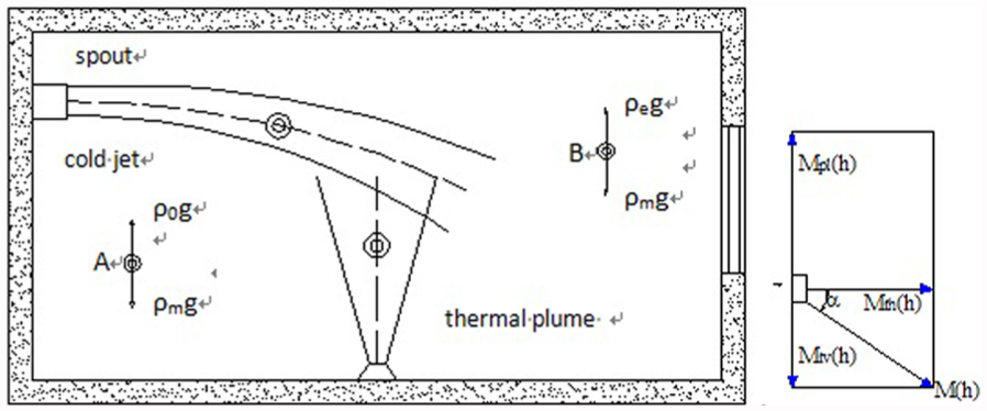
Horizontal cold jet of air-conditioning and thermal plume levels were stress analyzed; it shows that cold jet by a vertical downward force has downward movement, while the thermal plume by the vertical upward force has upward movement. After the campaign for some time, at some height, cold jet and thermal plume will encounter. At the same time, the plume begins to have an impact on the jet.
Force analysis of the nonisothermal level jet
For air-conditioning horizontal nonisothermal jets, use cold jet density ρm and ambient air density ρe to conduct stress analysis of nonisothermal jets. The upward direction is positive. Air-conditioning horizontal jet exerts acceleration in the vertical direction, and the acceleration j in the downward direction is as follows 30

in which ρe (kg m−3) is the environment density, ρm (kg m−3) is jet axis density, v0 (m s−1) is the initial vertical component of the pivot velocity of the horizontal nonisothermal jet, vm (m s−1) is the vertical axis of the jet speed, ΔT0 (K) is the absolute Kelvin temperature difference between the jet pivot and the environment, and Te (K) is the ambient environment temperature.
Its curved trajectory y1 may be described by 27

in which g (m s−2) is the local acceleration due to gravity, d0 (m) is the nozzle diameter, α is the entrainment coefficient of the jet, and x (m) is the range of the jet.
When the air velocity is less than 200 m s−1, air resistance in the horizontal direction of the jet can be expressed as

in which vx (m s−1) represents the horizontal velocity of the jet and k represents the air resistance coefficient, which is expressed as

Horizontally up, consider mass per unit mass of m = 1, Newton’s second law is
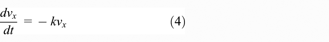
Integrate equation (4) to obtain

Using the initial conditions campaign time t = 0 (s) and x = 0 (m), it can be concluded that C = v0 (m s−1) and thus

Consider the jet trajectory (equations (3)–(6)), which then becomes a function of time t

Force analysis of the thermal plume
Use thermal plume density ρ and ambient air density of nonisothermal jets to analyze stress. 31 The upward motion of the thermal plume causes the vertical component of the accelerated velocity to be
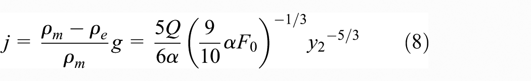
in which j (m s−2) is the vertical accelerated velocity component of the thermal plume, ρe (kg m−3) is the density of the environment containing the plume, ρm (kg m−3) is the axial density, α is the entrainment coefficient, F0 (m3 s−2) is the buoyancy flux of the thermal plume, y2 (m) is the vertical shift of the thermal plume, and Q (W) is the power of the heat source. The ascent height of the plume is
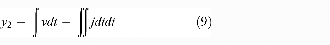
in which v (m s−1) is the thermal plume upward velocity.
Substituting equation (8) into equation (9) gives
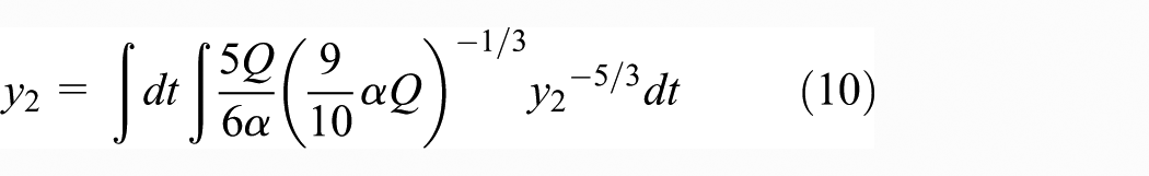
which, in turn, gives

Then, the ascent height of the plume during time period campaign time t is

The encounter and the interface of the single plume and the single cold air jet
Assuming the cold jet encounters the thermal plume at a height h (m). Integrating the descending equation (equation (7)) of the jet, the ascending equation (equation (12)) of the plume, and the constraint conditions of the plume and the jet, the moment at which the encounter occurs at time t and the interface h (m) of the two airflows can be calculated

It is assumed that the jet diameter d0 = 0.06 m, the supplied air velocity v0 = 2 m s−1, the supplied air height h = 1.6 m, the supplied air temperature t0 = 20°C, the indoor air temperature te = 26°C, the resistance coefficient k = 0.36, the coefficient of turbulence a = 0.12, and the entrainment coefficient of the plume α = 0.09. It is shown in equations (3)–(6) that when the distance s = 2.5 m, the descending distance of the jet trajectory is y1 = −0.9 m, and the jet encounters the plume at h1 = h − y1 = 0.7 m, as shown in Figure 1.

Trajectories of the jet and the plume over the time.
It is shown in Figure 1(a) that when the heat flux is Q = 500 W and the horizontal jet starts at 1.6 m high, the jet encounters the plume at about t = 0.6 s and h = 0.7 m. It is shown in Figure 1(b) that as the heat flux increases, the encounter height remains the same, and the time from the start to the encounter decreases. In Figure 1(b), t1 < t2 < t3, which indicates that when the horizontal jet is stable, the interface height is related to the distance between the plumes, while the time to first encounter is related to the heat flux. If the heat flux gets larger, the ascending velocity of the plume is larger and then the plume can encounter the jet earlier.
Interaction coefficient β of the cold jet and the thermal plume
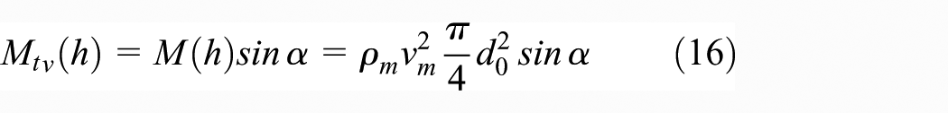
After the encounter between the jet and the plume, they will interact; this is based on the interaction of the horizontal and vertical force components in the jet and the plume, respectively. At the encounter height h, the momentum flux of the jet can be divided into Mth(h) in the horizontal direction and Mtv(h) in the vertical direction: the vertical momentum flux component of the plume is Mpl(h), as shown in Figure 2.
The decomposition of the momentum at the interface.
The interaction coefficient β of the jet and the plume represents the ratio between the momentums Mtv(h) and Mth(h) of the interacting units at the interface which has a height of h

The momentum flux of the cold jet can be expressed as
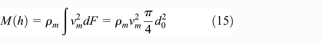
Thus

Based on the relationship between the velocity and the density of the jet pivot, the jet density ρm (kg m−3) and the initial value of the jet can be obtained 32 from

The jet trajectory curve function without the effect of plume(s) is

in which v0 (m s−1) is the initial vertical component of the pivot velocity of the horizontal nonisothermal jet, ΔT0 (K) is the temperature difference between the jet pivot and the environment, Te (K) is the ambient environment temperature, g (m s−2) is the local acceleration due to gravity, d0 (m) is the nozzle diameter, α is the entrainment coefficient of the jet, and x (m) is the range of the jet.
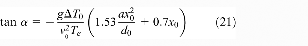
With regard to the fixed point (x0, y0), the slope of the tangent line is

It can be deduced that at (x0, y0)
The relationship between the pivot velocity and the initial velocity of the jet can be expressed as
Cold jet axis point in the upward decline in the vertical direction

The mass flux, buoyancy flux, and momentum flux of point source buoyancy plume 32


As for incompressible buoyant plume in nonhierarchical environment, N identically equal to 0. It can get solving expression for momentum flux of point source buoyancy plume control equation


in which Gu(z) (m3 s−1) is the mass flux of point source buoyancy plume, Mu(z) (m4 s−2) is the momentum flux of point source buoyancy plume, and Fu(z) (m4 s−3) is the buoyancy flux of point source buoyancy plume.
According to the initial value of the parameter jet nozzle v; environmental parameters ρe, Te, and ΔT; and interaction section of the jet velocity vm, formula (18) can be solved for the density of the jet interaction section ρm, and formula (22) can be solved for the interaction of the jet axis velocity section vm. Joint formulas (16), (17), (21), and (25)–(27) can obtain the interaction parameter β, and the value of β determines deviation degree between the jet trajectory and strength of thermal plume and cold jet plume interactions.
To discuss the relationship changes in the interaction parameter β, it is assumed that jet air-supply velocity v0 = 2, 3, 5, and 10 m s−1, air-supply temperature Tm = 20°C, air-supply height h = 15 m, nozzle diameter d0 = 0.06 m, indoor environment temperature Tε = 26°C, and turbulent coefficient α = 0.12 as shown in Figure 3.

Jet trajectories under different plume flow effects: (a) v = 2 m s−1, (b) v = 3 m s−1, (c) v = 5 m s−1, and (d) v = 10 m s−1.
As Figure 3 shows that jets exhibit effect under thermal plume, it is found that the interaction parameter β is <0. With the increase in the range of the jet trajectory, cold jet dropped distance increases. The absolute value of the interaction parameter β is increasing, indicating that jet in the initial has large jet velocity, good rigidity, and weak influence on the thermal plume. As Figure 3 also shows that with the increasing heat source, the greater the absolute value of the interaction parameter, the greater the effect of cold jet interference. It can also be seen from Figure 3, the larger the absolute value of the interaction parameter is, the greater the effect of cold jet interference is. At the same time, it can be seen that the interaction parameter β is related with the jet plume source location, which is related to jet with plume spacing x, and the discussion is divided into three cases:
If x is in the initial section of the jet, the thermal plume interference on cold jet is relatively weak, and cold jet will be coerced thermal plume movement.
If x is located in the main section of the jet, after the cold jet has moved some distance, rigidity is weakened, interaction unit body continues to move forward, and cold jet offsets phenomenon previews.
If x is located in the end section of the jet, cold jet has entered the lower staff work areas of the large space, momentum in the vertical direction of the thermal plume is dominated, and jet trajectory offsets phenomenon obviously. If the thermal plume flux is absolute dominant, there will be movement on coerced cold jet limiting case, and the jet will be shifted upward trajectory.
Test measurements
The model of interaction coefficient was evaluated using test-room experiments. Velocity distribution and the trajectory of the cold jet and the hot plume of thermal plume were obtained in testing laboratory; the experimental value of interaction coefficient was obtained through the analysis of changes in cold jet trajectory and the impact of the thermal plume on cold jet movement, which was also compared with the theoretical calculation of interaction coefficient to verify the reliability of the theoretical model. In this article, the experimental study is focused on the interaction between single plume and single jet. In total, two strands of equal plume and unequal plume are also carried out in the experiment.
The schematic structure of the environmental laboratory building and air-conditioning system layout are shown in Figure 4. The laboratory air-conditioning system ensures the sent key air temperature and velocity and also ensures that the jet interferes in other motions, such as infiltration air movement and the envelope structure heat transfer.

Schematic structure of the environmental laboratory building and air-conditioning system layout.
The model was evaluated by test-room experiments. Test room experiments are carried out to evaluate the above-mentioned mathematical model. The test-room was 5 m in length, 3.5 m in width, and 2.5 m in height. A convector heater was used as the heat source for the plumes, which is capable of creating a heat flow up to 1000 W.
The thermal plume is generated from the lawn lamp, for simulating point source plume (Figure 5). Different power of tubes was changed to satisfy the requirements of the heat source of plumes. In this experiment, an air-supply nozzle with a diameter of 0.6 m was located close to the middle of the shorter wall of the test-room at a height of 1.6 m. The plumes are located 1.5 m below the nozzle. A Venturi was used for serving as an air-supply nozzle. An anemometer was used to measure the air velocity, while thermocouples were adopted to measure the ambient temperatures and the air supply. And Delta OHE universal wind instrument was also used.

Lawn lamp design structure for simulating thermal plume.
The experimental conditions are shown in Table 1, and Table 2 shows the basic parameters.
Experimental conditions.
Delta OHE universal anemometer.
In order to match the motion feature of point source plume, the jet radius of lawn lamp b and flow height x should meet the requirements of equation (31), 10 and the entrainment coefficient α = 0.09. According to the calculations of equation (31), the following can be identified: b = 30 mm and x = 300 mm

There were, in total, 924 measuring points recorded for each experimental condition listed in Figure 6. The x–y plane lies in the laboratory floor, while z is in the altitude direction of the laboratory. In total, 12 horizontal measuring rows were arranged in the vertical direction from 0.5 m to the nozzle height of 1.6 m with an equal interval of 0.1 m. Each measuring row included seven measuring points with the following different intervals of 0.3, 0.2, 0.1, 0.1, 0.2, and 0.3 m, respectively, in the y-direction. The choice of different intervals is mainly according to the rapidly changing velocity gradient around the pivot. The measuring points in the x-direction are totally 11, with an equal interval of 0.3 m.

Layout of measuring point coordinates.
A total of seven universal anemometers with unequal spacing in the Y-direction on air vents’ horizontal distance of 0 positions are arranged. Completely 84 mobile test positions were listed in the region every 10 cm along the Z-direction. Next, the other measuring points is also set along the X-direction in the next test area.
In order to ensure the accuracy of the experiment, each measuring point, every 1 min a group of data, records a total of three sets of data, and the average value is taken as the test data of the measuring point. Replace the lawn lamp source for other conditions during the experiment, need to readjust heater position, ensure that the indoor temperature stabilizes at 26°C, and then measure these measuring points.
Results
A total of 120 velocity values obtained from the vertical section in the experiment are input to the MATLAB to obtain the isokinetic diagram, as shown in Figure 7. Figure 7 shows that the jet trajectory will be elevated under the influence of the plume, and this is in agreement with the analytical result, which indicates that different amounts of heat will influence the jet trajectory to differing extents. With the increase in the amount of heat, the elevation of the trajectory is clearer. For example, at s = 3 m, the trajectory at Q = 1000 W is approximately 0.5 m higher than that at Q = 150 W. The phenomenon shows that for a single plume, the effect of the amount of heat on the jet trajectory is clearer with the increase in heat, and the buoyant force increases with the heat. It is also shown in Figure 6 that the influences on the jet trajectory all begin to emerge at s = 1.5 m. This is because the plume is located directly under the jet at s = 1.5 m, where the jet starts to be influenced by the plume, and the interaction emerges.

Isotachs of the jet sections (section Y) under four conditions.
According to the experimental data, when Q = 150 W, the interface at which the jet and the plume meet is 1.5 m high, the local velocity is 0.29 m s−1, and the average density of the section is

Substitute this value of ρm into equation (14) to obtain the interaction coefficient β
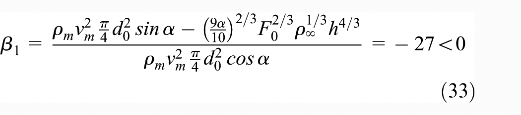
It can be deduced that when Q = 300 W, β = −43; when Q = 500 W, β = −64; and when Q = 1000 W, β = −102.
The values above indicate that with the effect of the plume, the interaction coefficient β is less than 0, and the plume will influence the jet trajectory, and with an increasing amount of heat in the system, the absolute value of the interaction coefficient increases, and the effect is larger, which is in agreement with the aforementioned analysis of the interaction coefficient. As shown in Figure 8, the calculated, and experimental, results for interaction coefficient β are in agreement, which validated the mathematical model.

The comparison between experimental values and theoretical values.
Discussion
Analysis of jet trajectory experiment results under single-stranded plume effect
Figure 9 shows that the plume leads to a significant uplift in jet trajectory, which is consistent with the theoretical analysis; different heat produces different effect which results on the jet trajectory. When the jet air-supply velocity is certain and air-supply height h is 1.6 m, due to jet influenced by plume buoyancy, the trajectory will be offset. When heat source Q is 150 W, jet trajectory lifts range at nearly 0.5 m at the horizontal direction range. At this time, with the increase in heat source, a greater degree of uplifting will occur in the jet trajectory. For example, when Q is 1000 W, jet trajectory uplifts nearly 1 m at the horizontal direction range. They show that as for the single-stranded plume, the increase in the heat source results in a more obvious impact on jet trajectory. It also indicates that the greater the heat source, the greater the buoyancy generated. It can also be seen from Figure 8 that, basically with the position in the horizontal direction, there is an obvious effect on the jet trajectory, mainly because of the plume located just below 1.5 m in the horizontal direction of the jet. Then, jet began to be affected by plume buoyancy, hot and cold air began to show obvious interaction.

The influence law of different conditions of jet trajectory.
Analysis of jet trajectory experiment results under isocaloric single-stranded and multi-stranded plume effect
Figure 10 reflects experimental results of single-stranded and two strands of equal plume effect on jet trajectory; single-stranded plume and its isocaloric two strands of equal plume impact on jet trajectory is basically the same, which is consistent with the theoretical analysis results, mainly because single-stranded plume and its isocaloric two strands of equal plume have the same density varying trends in the same range of height. The average density difference is only about 0.02 kg m−3. This previous theoretical analysis also described the impact of the plume on jet trajectory performance indicating that plume impact on jet generates effect of thermal buoyancy, and thermal buoyancy and density have a function relation. Thus, if the average density of the two plumes is the same, the influence on the jet trajectory is also the same.
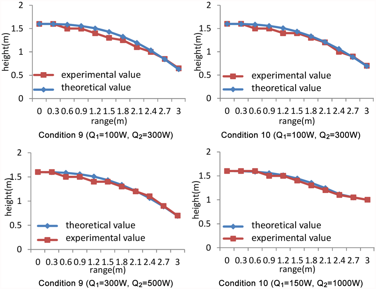
Comparison of theoretical value and experimental value of conditions 9, 10, 11, and 12.
Analysis of jet trajectory experiment results under two strands of equal plume effect
Comparison conditions 6, 7, and 8 impact on the jet trajectory as shown in Figure 11. The two strands of equal plumes that act on the jet trajectory are also proportional to the heat source; the greater the heat, the stronger the jet trajectory uplifts. It is shown in Figure 10 that when the jet air-supply velocity is certain, and air-supply height h is 1.6 m, under the three conditions Q1 = Q2 = 150 W, Q1 = Q2 = 300 W, and Q1 = Q2 = 500 W, the jet trajectory lifting successively increased at the horizontal direction range. However, due to the small gap between the heat sources of different working conditions, the impact difference of jet trajectory is not great.

Experimental value comparison between two unequal and two single-stranded plumes.
Analysis of jet trajectory experiment results under two strands of unequal plume effect
As shown in Figure 12, when the horizontal direction ranges from s = 0 m to s = 3 m, the working conditions 9, 10, 11 uplift at the same effect on the jet trajectory, especially in the two conditions of Q1 = 100 W, Q2 = 500 W and Q1 = 300 W, Q2 = 500 W, the influence to jet trajectory is basically same in the range of the jet. And Q1 = 150 W, Q2 = 1000 W working conditions and a single-stranded plume Q = 1000 W condition have the same trend in jet trajectory difference, which shows that the two unequal plume has impact on jet trajectory, although the impact intervention between two single-stranded plumes. But the single-stranded plume with greater heat source has a predominate impact on jet trajectory. The condition with Q1 = 150 W, Q2 = 1000 W, which contains a large power heat source 1000 W, leads to the result that jet trajectory in the range s = 3 m raises nearly 0.15 m in comparison with the other three groups.

The influence of the plume position on the jet trajectory.
Figure 13 reflects the interaction between the thermal plume and the cold jet. The increasing coefficients of interaction mean that the intervention of the thermal plume on the cold jet is more evident. When the air-supply velocity increases from 2 to 10 m s−1, the variations in interaction factors are the same but with larger amplitudes. When the air-supply height is 1.6 m, the air velocity is 2 m s−1, improving the heat source from 150 to 1000 W, the interaction factors begin to be evident at s = 0.9 m, which shows that the elevation of the cold jet is caused by the thermal plume. The elevation begins to be evident at s = 1.5 m. When the air velocity is increased to 5 m s−1, with increased heat at its source, the elevation of the thermal plume begins to become evident. However, for an elevation of s = 3 m with a velocity of 5 m s−1, the induced elevation is smaller than that at 2 m s−1 because of the increase in the air-supply velocity leading to an increase in the rigidity of the jet, a decrease in the buoyancy force acting on the thermal plume, and a concomitant decrease in the extent of the interaction. Obviously, the increase in air-supply velocity of the jet can reduce the effects of the intervention of the thermal plume.
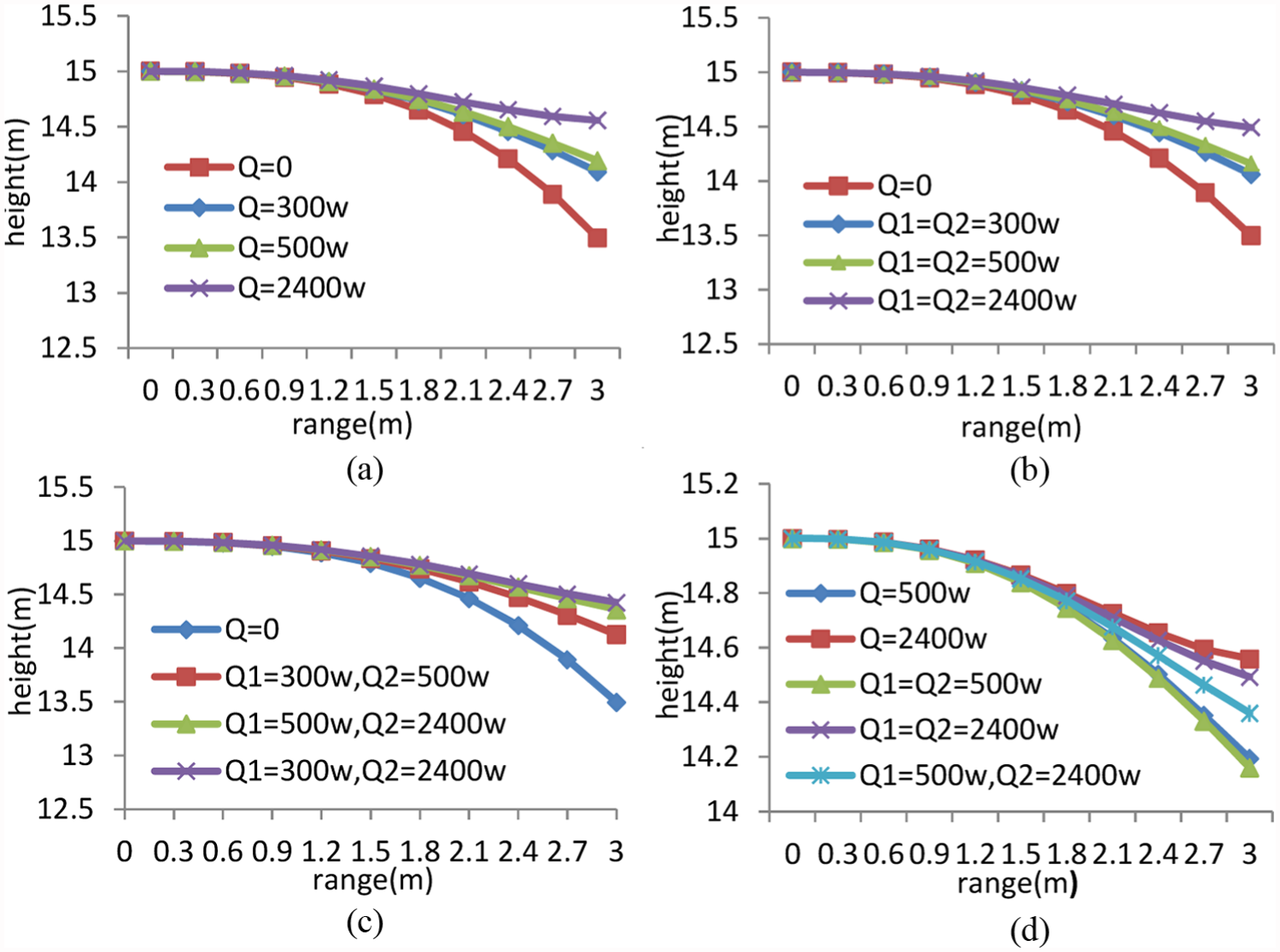
Jet trajectories under different plume flow effects: (a) v = 2 m s−1, (b) v = 3 m s−1, (c) v = 5 m s−1, and (d) v = 10 m s−1.
Conclusion
An interactive mechanism model of a jet and a plume in a large space has been established. The interaction coefficient β has been established, and the variation rate and the interference of the plume in the jet trajectory are all discussed. However, design calculations of nozzle jet trajectories in large-space air distribution only take the vertical bending into account which is caused by the temperature difference between jet and ambient air. Design calculations show errors as the interaction between the jet and plume is neglected. In this article, the mathematical model of interaction is established and studied in detail, which provides a theoretical basis for future revision of design calculations.
The analysis indicates that under the effect of the plume, the interaction coefficient β is less than 0, and as such, it will influence the jet trajectory. As the supplied heat increases, the absolute value of β increases, and the effect on the trajectory becomes more evident.
The model of interaction coefficient was evaluated using test-room experiments. Velocity distribution and the trajectory of the cold jet and the hot plume of thermal plume were obtained in testing laboratory. The experimental value of interaction coefficient was obtained through the analysis of changes in cold jet trajectory and the impact of the thermal plume on cold jet movement, which was also compared with the theoretical calculation of interaction coefficient to verify the reliability of the theoretical model.
For a single-stranded plume, the greater the heat source, the greater the impact on jet trajectory. When the heat source Q = 1000 W, air-supply velocity v0 = 2 m s−1, and air-supply height h = 1.6 m, at the horizontal direction range s = 3 m, jet trajectory is lifted about 1 m. For the two strands of equal plume, the effect on the jet trajectory is similar to isocaloric single-stranded plume. In terms of the impact of two strands of unequal plume on the jet trajectory, the plume with larger heat source plays a dominant role in the intervention between two single-stranded plumes.
Footnotes
Academic Editor: Oronzio Manca
Declaration of conflicting interests
The author(s) declared no potential conflicts of interest with respect to the research, authorship, and/or publication of this article.
Funding
The author(s) disclosed receipt of the following financial support for the research, authorship, and/or publication of this article: This work was supported by the National Natural Science Foundation of China (grant nos 51108263 and 51278302) and the Natural Science Foundation of Shanghai (grant no. 16ZR1423200).