
Abstract
This paper deals with analyzes of the influence of the perpendicularity of the spindle of the milling machine on the machined surface. This is part of the geometric errors of machine tools and in a direct manner constitutes a defect on the quality of the workpiece. Therefore, the surface roughness is particularly sensitive to the cutting speed, the feed rate, round of teeth default, the tool tip radius and the cutter teeth number. This article examines the characteristics of the surface topography of steel parts, in finishing machining using milling cutters. The study is conducted by computer simulation tests and experimental part using surface condition monitoring instruments, taking into consideration the round teeth default. The variation of the inclination of the spindle of the milling machine in three positions (90° + 30′, 90°, and 90°–30′) shows a good agreement between the simulation and the experimental results for sharp and moderately worn tools. Similarly, this study showed that the presented model could thus be integrated into systems computer-aided design and computer-aided manufacturing. Finally, the physical and statistical parameters of roughness during milling at position 90° confirmed that, when the defect of the perpendicularity is eliminated to the maximum, the best surface conditions are obtained.
Introduction
Face milling is one of the most commonly used material removal processes in the industry. Cutting operations by end machining are used for finishing surfaces such as medical prostheses, dies, molds, turbine blades, and aero-nautical parts. These products have very strict specifications in terms of surface quality which, in most cases, represents a technical requirement for these products. 1 Obtaining a high-quality machined surfaces with vertical milling is of great interest to researchers and those involved in surface machining. The final milling surface quality is the result of the influence of a number of factors such as machine tools stability, the correct choice of cutting tools, the correct choice of cutting tools, properties of machined materials and the angle of inclination of the tool on the normal surface. To have good results, all these factors should be carefully chosen in order to avoid minimal negative influences in the process. Using an angle “α” between the axis of the tool and the surface to be machined, one can contribute to a better quality of machined surface. Nevertheless, the majority of the research related to the surface roughness generated in the spherical end milling, focuses only on a geometric kinematic basic model.5,6 For this reason, this work contains the analysis of the surface roughness generated in vertical milling including the deviation of the angle of perpendicularity with respect to the surface shortness and minimum thickness. The single direction of upward vertical tool orientation was deliberately selected to demonstrate a better understanding of how to obtain an optimum machined surface. This paper contains the analysis of the surface roughness generated in vertical milling with 6 and 12 cutting tooth, including the angle of inclination of the surface.
Defining the problem
The appearance of a machined surface in vertical milling is characterized by a series of intersecting curves called cycloids corresponding to the trace left by the teeth of the cutter on the part.6,7 During machining, the mill axis is substantially perpendicular to the machined surface, we take three positions of the axis of the milling cutter in order to optimize the quality of the surface state, reducing the applied load to the machine tool and save operation of other machine tools. Indeed, we note that the signatures of the milling cutter on the surface state have changed during the machining in the three positions of the axis of the milling machine. Does the physical and statistical characteristics of the roughness vary, or remain constant, if we take the cutter spindle position that should be?
Principle of the algorithm of the inclination of the angle of the tool
First, we present a workpiece on the machine tool (vertical milling), with the chosen cutting speed, the feed rate and the number of teeth equal to 6 and 12 (as shown in Figure 1(a)). In addition, the mill axis forms an angle α with the surface to be machined.
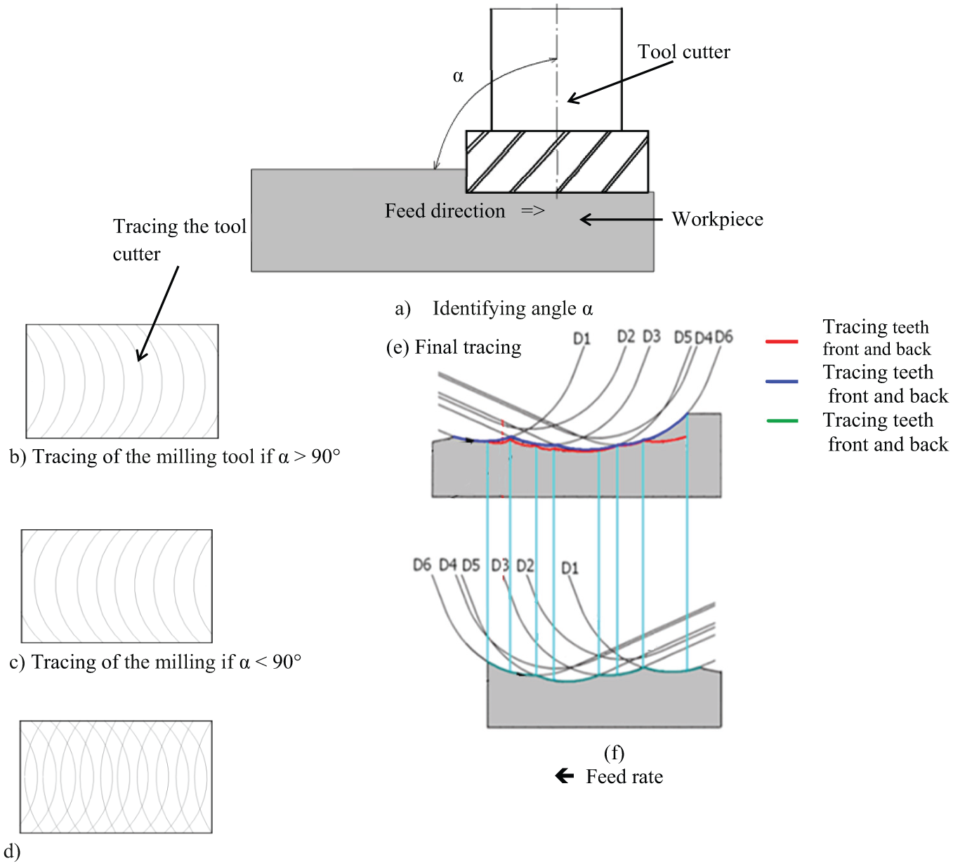
Machining algorithm not end milling with milling cutter positions.
Taking three positions of the axis of the spindle according to the angle α, we obtain the following:
At the angle α = 90° + 30′, the surface of the part is machined by the front teeth (as shown in Figure 1(b)).
At the angle α = 90° – 30′, the surface of the part is machined by the back teeth (as shown in Figure 1(c)).
At the angle α = 90°, the surface of the part is machined by the back and front teeth (as shown in Figure 1(d)).
The machining by the front teeth of the cutter is represented by the tooth D1, D2, D3, D4, D5, and D6, according to the runout of the teeth (as shown in Figure 1(e), blue color).
The machining by the back teeth of the cutter represented by the tooth D3, D4, D5, D6, D1 and D2, according to the runout of the teeth (as shown in Figure 1(f), green color; angle α = 90° – 30′).
Intersection between the back and front tooth depending on the color advance speed as show in Figure 1(e) (angle α = 90°).
Model of surface roughness by the milling process
When designing the algorithm, the following parameters are taken into account and are considered as inputs: cutting speed Vc, the feed rate of the workpiece vf, the radius of the tool nose rε, the runout nose of cutter according to the following axes ox and ozεr, εa.4,6
The outputs must be represented by the coordinates xi, zi for each point mi of the surface to be machined. A series of simulations are carried out to evaluate the performance of the model developed with the validation of results. For these simulations, we are mainly interested in the theoretical roughness (third-order defect), which depends on the following essential parameters: the geometry of the cutting tool, the advance of the tool, and the number of teeth of the cutter. The simulation is done in three steps:
Generating a point file with the use of a program. These points represent coordinates xi, zi, and point mi belonging to the machined surface.
The generated points are introduced in the Surface Excel. To reproduce the corresponding figure, they represent the virtual image of the surface obtained by the two-dimensional surfacing operation.
Calculating physical and statistical roughness parameters to compare the two results that are obtained.
Equation
Figure 2(a) shows the position of milling cutter on the workpiece, such that the number of teeth is equal to 12. to illustrate geometrically the cutting parameters which intervene on the machined surface curve (as shown in Figure 2(b)). The value of each graduation if the displacement is total is equal to the turn of the milling cutter (Figure 2b):


(a) Position of the cutter on the workpiece and (b) geometric relationship between the insert profile and runout.
Estimating the instantaneous value of the path length of the mill along the axis x, we take the integer of displacement equal to j2,3

The point coordinate m0 (as shown in Figure 2(b)) is obtained as follows


Now, we calculate the point coordinates


By expressing the nose circle equation of the cutter tooth, which is bounded by the points m0 and mn: (see Figure 2)
Experimental part and simulation
Experimental equipment
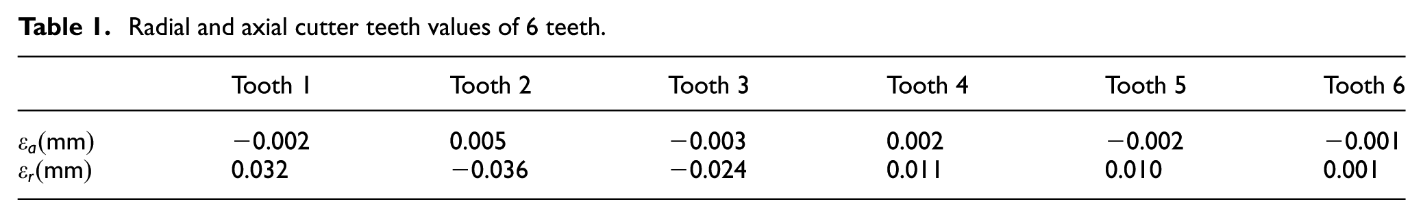
The Laboratory of Metrology and Mechanical Manufacture allows us to carry out the experimental part on ductile steel workpiece fine non-allied steel (C40, C % = 0.4, Mn % = 0.5, Cr % = 0.4, Ni % = 0.4, Mo % = 0.1). Machined on type FU 2.5 (PMO) milling machine, the specification of the cutting device (The milling tool 6, 12 teeth of Metal carbide), and the runout of the cutter which are measured by the comparator (See Tables 1 and 2). We consider a system that completely reflects the properties of the rugosimeter as shown in Figure 3.
Radial and axial cutter teeth values of 6 teeth.
Radial and axial cutter teeth values of 12 teeth.


(a) The mounting of the control of the workpiece by the rugosimeter and (b) workpiece machined by milling at the end of teeth 6.
We use the type rugosimeter TR200 with a standard probe TS100, such that the tracing speed is equal to 18 mm/min and the measured length is 1.8 mm. The measured data are amplified, and then processed by the computer with a converter A, as shown in Figure 3(a) and (b).
Sampling dimensional parameters
The experimental part performs on a certain sample of hard C40, with dimensions 35 mm, 35 mm, 10 mm, at holding temperature 25° (as shown in Figure 3(b)).
Tables of experimental data and simulations
Tables below show the specific values of experimentation and simulation, the cutting conditions, the geometric dimensions of the workpiece, the cutting angle, and the main steering angle γ = 18°, kr = 45°.
Cutting conditions.

To determine the values of the radial and axial runouts of the teeth of the 6 tooth cutter, fixing the cutter on the machine tool (a vertical milling machine). Using a flat-head micrometer comparator as it is carried by the support. The first phase axially tangents the comparator probe with the nose of the cutter to measure the axial runouts of the first tooth then of teeth with teeth up to the sixth tooth. The second phase, contact probe and beak of the cutter radially.11,12 We measure the radial runouts of the first tooth, it is the same for the 6 teeth. The following table 1 follows:
Taking the values of radial and axial runouts of the teeth of the 12 tooth milling cutter with the same way of 12 teeth. It gives us the following table.
Experimental study and simulation of profiles
Simulation of surface profiles
The curves shown in Figures 4–9 give us the surface profiles of a workpiece machined by the milling machine (simulated and real). The axis (ox) indicates the measured length of the profile in mm (the value taken 1.8 mm as maximum). The axis (oz) shows the elevation (waves) of the profile in millimeter; the maximum value varies from −0.015 at +0.015 mm.

Simulated surface obtained by the front teeth of a 12-tooth milling cutter.

Simulated and Real surface obtained by the front teeth of a 12-tooth milling cutter.
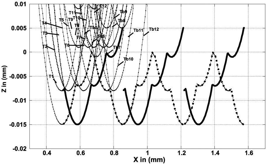
Simulated surface obtained by the front and rear teeth with a 12-tooth milling cutter.

Simulated and real surface obtained by the front and back teeth of a 12-tooth milling cutter.

Simulated surface obtained by the front and back teeth with a 6-tooth milling cutter.
Surfaces obtained simulated and real by the front and rear teeth with a 6-teeth milling cutter.
The numbers 1 to 12, in Figure 4, show the traces of teeth according to their numbers with out-of-round deflections of each tooth. The three resulting profiles (the continuous bold curve and the discontinuous bold curve, signify the signatures of the three turns of the cutter by the front teeth.
The black profile in Figure 5 illustrates the simulated surface condition with the length of 1.8 mm after transferring to zero. The profile in red is measured by the rugosimeter, held according to the experimental conditions.
Both real and simulated profiles are consistent, the result of calculation of statistical and physical parameters is very close (Figure 10).

Physical quantities and statistics of roughness surfaces manufactured by the 12- and 6-teeth cutter.
The numbers 1–12, in Figure 6, show the contours of the teeth according to the numbers with runout deviations. The two resulting profiles (curve in line bold contained black, bold discontinuous in black which give the two resulting profiles (Curve in line bold contained black, bold discontinuous in black which give the signatures the three turns of the cutter by machining with the front teeth from 1, 2, 3, 4, 5, 6, 7, 8, 9, 10, 11, and 12. Machining begins with teeth back 6, 7, 8, 9, 10, 11, 12, 1, 2, 3, 4, and 5 successively.
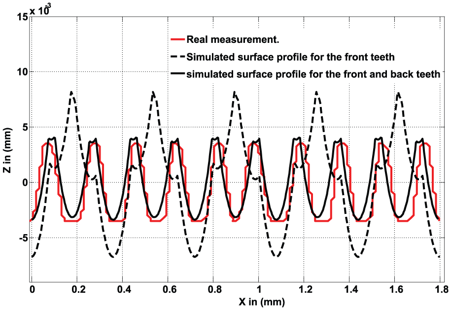
The black profile in Figure 7 illustrates the profile of the simulated surface condition with a length of 1.8 mm after having transferred to the zero point of a workpiece machined by front and back teeth of the cutter. The discontinuous black profile shows the tracing of the front teeth. The profile of the surface condition simulated with a length limit, and the profile in red is measured with the rugosimeter.
Indeed, we note that the profile of the surface condition machined by the front and back teeth and by the front teeth is different. Finally, the good the surface condition that is machined by the front and back teeth is better than the latter.
The numbers 1–6, in Figure 8, show the contours of the teeth according to the numbering with their deviations of the outline of the tooth. The three resulting profiles (the curve continues in black bold line, the discontinuous curve in black bold line) which give the signatures of the three turns of the milling cutter by machining with the front teeth following the digitization of the teeth 1, 2, 3, 4, 5 and 6, back teeth start at 3, 4, 5, 6 and 1.
The black profile in Figure 9 illustrates the simulated surface condition of the length at 1.8 mm after transferring to zero of a workpiece machined by front and rear teeth of the cutter. The profile in red is measured by the rugosimeter. The two profiles of the surface condition machined by the front and back teeth and by the front teeth show different results. That is to say, the good surface is machined by the front and back teeth than the last (see the characteristics of the roughness in Figure 10). Calculating the simulated values and real values of the roughness quantities as follows: Simulated values:
Analysis and discussion
After recording the curve of the surface state by the rugosimeter, by simulation, we determine the physical and statistical parameters of the roughness of these machined surfaces, which are obtained from the 6- and 12-teeth cutters, by performing the simulation of the surface profiles, holding the same cutting conditions. Figure 10 shows the calculation of the characteristics of the roughness. y axis is calculated in micrometer, with x-axis as Ra, Rp, Rm, Ry, Rq. Each entity contains four parameters of surface control quantity (Ra12,
R12: The roughness of the workpiece by the front teeth with a 12-teeth milling cutter.
R6: The roughness of the workpiece machined by the front teeth with a 6-teeth milling cutter.
R12: The roughness of the workpiece machined by the front and back teeth with a 6-teeth milling cutter.
These figures show the control of the surface profile for two turns of the cutter and express the comparison between the two surfaces machined with two milling cutters whose number of teeth and the position of the axis of the spindle are different (as shown in Figure 10). The latter two parameters also express the progression of the values of the columns according to each magnitude of the roughness. In this context, we summarize that the machining by the cutter of small number of teeth brings a good result concerning the state of surface of the workpiece. It can also be concluded that the perfect perpendicularity of the spindle of the milling machine gives us a good surface condition, as shown in Figure 10, and the cutting forces are reduced only if the number of teeth of the cutter is larger.
Recommendations
From the results obtained, it is evident that the effect of the angle of inclination of the spindle axis influences the surface quality generated. As for five-axis machining, it allows us the inclination between the cutting tool and the surface to be machined. For this, the roughness of the surface obtained by this process must be improved. Moreover, the problem of machining in three axes the existence of very low cutting speeds, When the axis of the spherical end mill is normal to the surface of the part strictly, this machining mode produces a poor quality of the surface roughness, leading to surfaces of poor topography.
The inclined milling with the hemispherical tool directs a variation of the effective cutting speed which depends on additional parameters of the cut such as the angle of inclination and the path of the tool, and other operational parameters are as follows: radial depth, cutting speed, and feed rate by tooth dent. To get a good flat surface condition, it is better to use the vertical spindle milling machines. The change in runout sizes should be limited to a short interval.11,15 The modeling of the vibrations is also possible from these data and the dynamic behavior of the active part (tool, tool holder of the spindle, and angle of inclination) can be analyzed. The vibration effect of the machine can be explained by superimposing the vibratory motion on the nominal peripheral of the milling operation. For the purpose of simulating a component, random vibration normal to the machined surface was added.
Finally, it has been shown that predetermination of the quality of manufactured surfaces can be supported by the use of the proposed model. All these themes illustrate the advantage of developing realistic and physical simulation tools to optimize machining processes.
Conclusion
Deviation analysis of the spindle axis perpendicularity of the milling machine by contribution to the machined steel surface C40 plays an important role on the quality of the surface state of a part by fixing all the cutting parameters, neglecting the vibrations8,9 of the machine, cutter, the expansion factor of the part, and the material of the tool. By applying the end milling process to achieve the surfacing, the geometrical parameters of the tool, the cutting angles, the beam radius of the tool, and the misalignments of the teeth are taken into account. As a result, machining by the front or back teeth by the milling cutter does not give a good surface finish after calculating the static and physical parameters of the roughness. The milling tool teeth does not depend on the quality of the surface condition. Machining the front and back tooth positively affects the machined surface roughness. As we know it, milling cutter that has many tooth are expensive, difficult to machine, and fragile; hence, it is better to avoid this type of milling cutter. In order to achieve a better model of profile of the surface, which gives us a good signature of teeth on the surface of a workpiece, the tolerance of the faux tooth is increased.
Footnotes
Appendix 1
Acknowledgements
The authors would like to thank Prof. Aour Benamour of the laboratory of applied biomechanics and biomaterials, ENP Oran, PB1523 El’Mnaour 31000, Oran, Algeria, for their contribution to this study.
Academic Editor: Noel Brunetiere
Declaration of conflicting interests
The author(s) declared no potential conflicts of interest with respect to the research, authorship, and/or publication of this article.
Funding
The author(s) received no financial support for the research, authorship, and/or publication of this article.