
Abstract
An efficient and accurate thermo-fluid-coupled analysis is the basis of structure design and optimization for high-heat-flux components in neutral beam injection system of Experimental Advanced Superconducting Tokamak and has an important significance of exploring the optimal structure of components and realizing the temperature control of components at a high-parameter steady-state condition. In this article, take the calorimeter in the Experimental Advanced Superconducting Tokamak–neutral beam injection system on the thermal inertia principle, for example, an accurate numerical solution method of thermo-fluid-coupled analysis based on the turbulent heat transfer is established and combined with the near-wall function model, and the working characteristics of three-dimensional calorimeter plate under different deposited beam powers are simulated and analyzed. The temperature distribution of solid structure and corresponding flow field under given cooling condition is calculated. The results obtained by the proposed method coincide well with experimental results, which validate this method. This study provides a potentially useful method for thermo-fluid-coupled analysis and structural design of other high-heat-flux components in the Experimental Advanced Superconducting Tokamak–neutral beam injection system.
Keywords
Introduction
Neutral beam injection (NBI) is an important auxiliary heating and maintaining method with the highest heating efficiency and clearest physics mechanism for Tokamak and has been used in the world’s first Experimental Advanced Superconducting Tokamak (EAST) designed and developed by China.1,2 The principle of NBI system is that high-energy charged particles were transformed into neutral particles to be injected into Tokamak to heat the plasma and to maintain the heating temperature. Therefore, there are many high-heat-flux (HHF) components inside the NBI system. For example, the calorimeter which was used to absorb and measure the beam energy, and to get the transient energy profile by the thermocouple, is a typical HHF component. It is very important to establish an efficient and accurate heat flow coupling analysis method for these HHF components of the EAST-NBI system to explore the optimal structure and obtain accurately working characteristics of the structure under different beam parameters, which could be the significant reference and guidance of the experiments of the NBI system.
Thermo-fluid coupling analysis and structure optimal design of HHF components of the NBI system have been one of the research hotspots in the field of nuclear fusion, and most of the researchers have conducted in-depth study and obtain lots of important results. The engineering design including thermal hydraulics for cooling and baking of all the plasma-facing components (PFCs) using finite element analysis of ANSYS software package for the SST-1 is completed, and the results of the thermo-fluid-coupled analysis led to a good understanding of the flow behavior and the temperature distribution in the tube wall and the different parts. 3 For the vertical targets of the International Thermonuclear Experimental Reactor (ITER) divertor, a hypervapotron cooling concept armored with flat tiles was considered, the promising predictive three-dimensional (3D) simulations model both the two-phase flow and the solid heat conduction within the hypervapotron structure with thermo-fluid-coupled analysis method of Neptune CFD and Syrthes was done. 4 For the domestic-related fields, the flow–solid coupling heat conduction model of water pipes is used to analyze the heat dissipation situation of outside target in the form of turbulent flow, after establishing the cooling structure of EAST tungsten divertor. 5 The numerical analysis using the thermo-fluid-coupled method for the ion dump of EAST-NBI system is also presented, which provided a useful tool for the structure optimum design of ion dump and guided the experiments. 6
In this article, according to the structural features of calorimeter of EAST-NBI system, an accurate heat flow coupling analysis and numerical computation method on turbulent heat transfer basic theory were established to realize the simulation of 3D working characteristics of calorimeter under different beam power deposition parameters. By comparing with the experimental measurements results, the analysis method and simulation results were checked, and the accuracy of the assumption and presuppositions in theoretical calculation were verified.
Calorimeter structure of EAST-NBI system
According to the working principle and engineering operational requirements of EAST-NBI system, calorimeter was fixed in the third spool of the vacuum tank and should be able to measure the condition parameters on the working status and the beam channel on the non-working status. The plate of the calorimeter of EAST-NBI can be able to achieve the measurement of beam parameters (beam power of 2–4 MW and the corresponding measurement time of 0.5–1 s). As shown in Figure 1, the calorimeter of EAST-NBI used the V-shaped structure composed of two splicing plates and adopted water flow calorimetry system to calculate the total deposition power with cooling water flowing inside the plate (the total mass velocity is 0.7 L/s). The size of the structure is as follows: the length of each plate is 867 mm, the width is 480 mm and the thickness is 15 mm. The layout of the cooling water tube consists of six rows with a distance of 45 mm between each line, which is embedded on the plate with the depth of 5 mm from the back of the calorimeter plate, and the diameter is 15 mm for one single tube. The opening angle of the V-shaped structure is 5°, and the plate was bending by an angle of 15° with the center line.
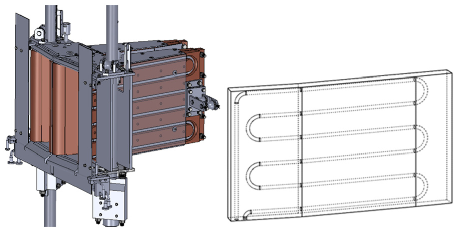
Schematic diagram of plate structure of EAST-NBI calorimeter.
Thermo-fluid-coupled method for EAST-NBI calorimeter
In this section, the control equations for turbulence and convective heat transfer of calorimeter plate will be established. The structure model is simplified and assumed as follows: (1) the fluid is a steady-state flow with no heat source inside, (2) the fluid is incompressible flow, and (3) the natural convection and thermal radiation are neglected.
The mass conservation equation
The increase in the quality of fluid in the unit of time is equal to the net quality inflow of the element at the same time interval, that is

Here,
The momentum conservation equation
Applying Newton’s second law in three coordinate directions of

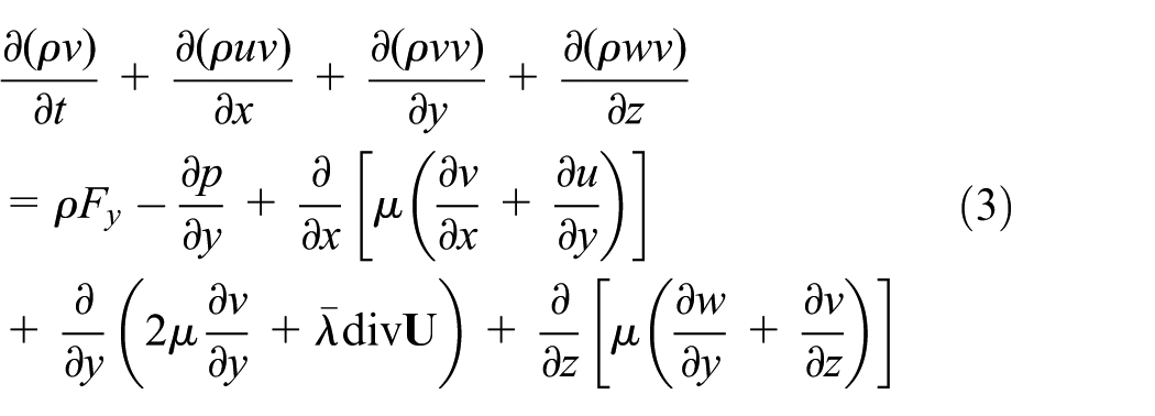
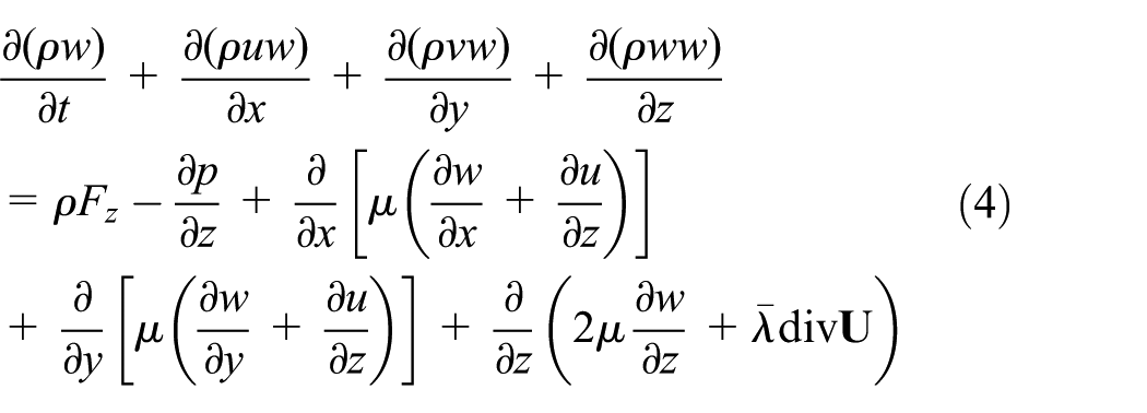
Here,
The energy conservation equation
The increase value of energy for the unit volume is equal to the net heat plus the power volume force done to the unit volume, and introducing Fourier’s Law, the energy conservation equation of the ideal fluid is as follows

Here,
For the actual process of heat transfer convection, the thermal–physical properties are the function of the temperature, thereby the velocity distribution and the temperature profile are impacted each other. In order to close the above equations, the physical property equation is induced to research the coupled relationship between velocity and temperature. Here, the fluid is a homogeneous thermodynamic system and is in the equilibrium state, so the specific form of the state equation is as follows

Turbulent numerical simulation is carried out by adopting Reynolds time-averaged equations with the turbulent viscosity coefficient method using the
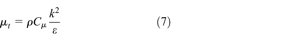
The turbulent kinetic energy


Here, Cµ, C1ε, C2ε, and C3ε are constants of the model; σk and σε are the turbulent Prandtl numbers for K equation and ε equation, Sk and Sε are the user-defined parameters.
The

Sketch map of gridding using wall function method.
Using wall function method, the logarithmic distribution law of time-averaged velocity

Here,
where

where
In order to establish the relationship between the temperature of the grid node and the wall physical quantity, the parameter

Here,
where
Then, the solution to the above equations is dispersed and can be solved by the finite volume method. The algorithm of turbulent convective heat transfer of calorimeter is shown in Figure 3.

Computational procedure of turbulent convective heat transfer for calorimeter.
Numerical simulation and experimental verification
Thermo-fluid-coupled simulation for EAST-NBI calorimeter
In this study, the grid of main body of copper plate is Tgrid, and the fluid region using copper Hex grid as shown in Figure 4. The material of main body is oxygen-free copper, the thermodynamic parameters of which are as follows: specific heat is 390 J/kg K, density is 8930 kg/m3, and the maximum surface temperature of Tcr is 573 K. Temperature of inlet cooling water is 303 K. The exit cooling water temperature is not exceeding 363 K, so the average qualitative temperature is 333 K, and the water thermodynamic parameters at this temperature are as follows: specific heat is 4.18 kJ/(kg K), density is 983.2 kg/m3, and viscosity coefficient is 0.000466 N s/m2. The heat flux loaded into the wall surface is assumed constant. According to the beam transmission characteristics of NBI system, the power distribution of the X and Y directions on the calorimeter plate is Gauss distribution as shown in Figure 5. When the extraction ion beam power of ion source is 4 and 2 MW, the corresponding beam power density distribution on heat flux surface is shown in Figures 6 and 7, respectively. The normal working pressure of the NBI cooling water system is calculated as the upper limit of the inlet pressure of the 0.3 MPa (the corresponding inlet velocity of 7 m/s).

The mesh of EAST-NBI calorimeter plate: (a) main part of copper plate and (b) fluid area.

The distribution of power deposition loaded on the calorimeter of EAST-NBI. 8
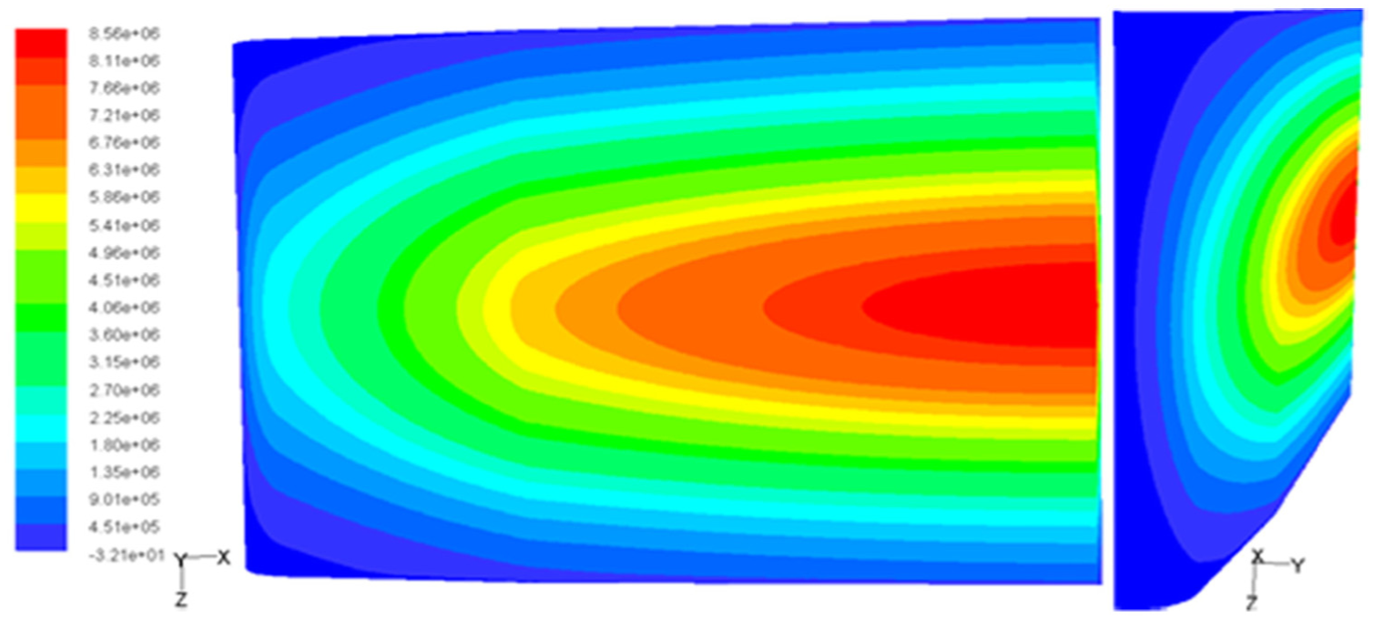
The power density distribution of the heat-loaded surface at the ion beam power of 4 MW.
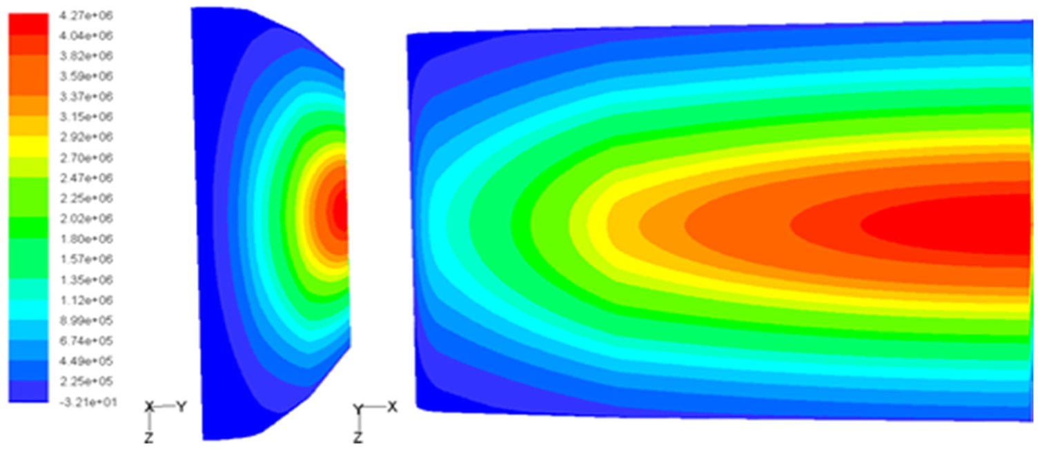
The power density distribution of the heat-loaded surface at the ion beam power of 2 MW.
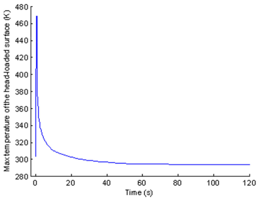
Considering the Gaussian distribution of the beam extraction profile, the maximum temperature on the heat-loaded surface of plate changing with pulse length is obtained by heat flow coupling method as shown in Figure 8. Set the soften temperature of copper (573 K) as the temperature upper working limit of the plate during calculation, the maximum pulse length under different extraction powers is obtained without deflection magnets on, which is 1.2 s corresponding to 2 MW and 4.6 s corresponding to 4 MW. When the neutral beam generated, the maximum pulse length under different extraction powers is obtained with deflection magnets on, which is 2.7 s corresponding to 2 MW and 12.3 s corresponding to 4 MW. At the beam power of 4 MW with heating time of 500 ms, the temperature distribution of the heat-loaded surface on the calorimeter plate with 90% of the ion beam deposited is shown in Figure 9, and the maximum value is 468 K. The maximum temperature of the heat-loaded surface of plate changing with time is shown in Figure 10. If the beam is switched off for 120 s, the surface temperature of the plate could recover to the normal temperature state at 297 K. And also, as shown in Figures 11 and 12, at the Gaussian beam extraction power of 2 MW with heating time of 1000 ms, the maximum value is 426 K and is recovered to the normal temperature state (297 K) after the beam is stopped for 120 s.

The upper limit temperature of the heat-loaded surface of calorimeter in the Gauss distribution under different injection conditions rising with the pulse length.

The profile of the temperature of the heat-loaded surface at the extraction power of 4 MW without the deflection magnet on (at 500 ms).
The maximum temperature of the heat-loaded surface versus the time at the extraction power of 4 MW and pulse length of 500 ms without the deflection magnet on.
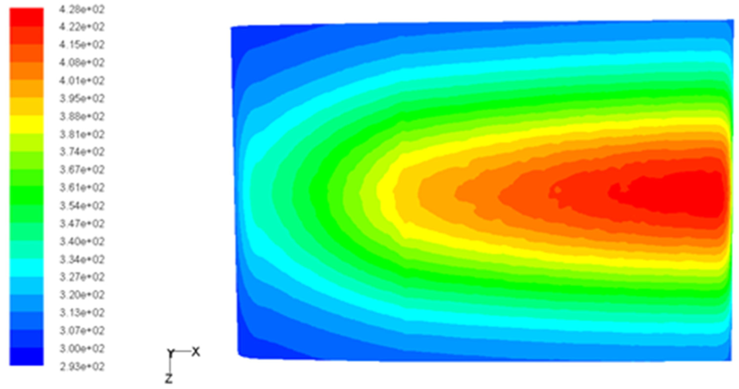
The profile of the temperature on the heat-loaded surface at the extraction power of 2 MW without the deflection magnet on (at 1000 ms).

The maximum temperature of the heat-loaded surface versus the time at the extraction power of 2 MW and pulse length of 1000 ms without the deflection magnet on.
It can be seen from Figures 9–12 that the temperature of the heat-loaded surface on the working condition is much lower than the softening temperature, and the cooling tubes could effectively control the rising temperature. However, the distribution of temperature is not uniformity and quite similar to the profile of the heat flux, so how to avoid the problem of thermal stress caused by long and repeated working condition will be the next step we need to pay more attention on.
Experimental verification
In order to verify the feasibility of this simulation method of calorimeter, the corresponding test was carried out in EAST-NBI test facility. The water inlet pressure of the cooling water system is set to 0.1–0.4 MPa during the experiment and the inlet temperature is set equal to the ambient temperature (293 K). The temperature measuring points are arranged on the two plates of the calorimeter, and the left and right plates are symmetrically distributed, as shown in Figure 13. The experimental conditions of beam extraction experimental shootings No. 26240 are as follows: the high voltage is 60 kV, the arc current is 34 A, and the beam extraction power is 2.04 MW with 1000 ms of pulse length, and the corresponding peak power density on the heat-loaded surface is 4.9 MW/m2, the inlet pressure of cooling system is stated as 0.3 MPa, the temperature obtained by the simulation proposed by this article, and the experimental measurement at the thermocouple NO.C17 with time is shown in Figure 14. And for shooting No. 26489, the beam parameters is as follows: the high voltage is 80 kV, the arc current is 42.5 A, the beam extraction power is 3.36 MW with 830 ms of pulse length, and the corresponding peak power density is 8.2 MW/m2, the inlet pressure of cooling system is stated as 0.3 MPa, the temperature obtained by the simulation proposed by this article and the experimental measurement at the thermocouple NO.C17 with time are shown in Figure 15.

The distribution of thermocouple.

Temperature variations at the thermocouple NO.C17 of shot 26240.

Temperature variations at the thermocouple NO.C17 of shot 26489.
It can be seen from Figures 14 and 15 that the results of the experiment are consistent with the simulation, which shows that the numerical calculation model proposed by this article is reasonable and the calculation accuracy is high. By calculation, the maximum error is controlled within 10%, which is mainly due to the influence of the factors such as radiation, two electron bombardments, and the thermal resistance of the local welding point on the contact resistance.
Conclusion
In this article, the basic theory and numerical simulation of thermo-fluid-coupled analysis method for the EAST-NBI calorimeter on the thermal inertia principle based on the turbulent heat transfer is established, and combined with the near-wall function model, the working characteristics of 3D calorimeter plates under different deposited beam powers are simulated and analyzed. The temperature distribution of solid structure and corresponding flow field under given cooling condition are calculated. The results obtained by the proposed method coincide well with experimental values, which validate this method.
The temperature of the heat-loaded surface on the working condition is much lower than the softening temperature, and the design scheme of the calorimeter plate with the inertia heat transfer method can effectively realize the temperature rise control but could not usefully change the uniformity of the temperature distribution. The corresponding thermal stress damage under prolonged load condition will be possible to bring the potential impact to the safe operation of the system. As a result, realizing the structure design optimization of EAST-NBI calorimeter is the problem to be solved in the next step. This study provides a potentially useful method of thermo-fluid-coupled analysis and structural design of other HHF components in the EAST-NBI system.
Footnotes
Academic Editor: Jiin-Yuh Jang
Declaration of conflicting interests
The author(s) declared no potential conflicts of interest with respect to the research, authorship, and/or publication of this article.
Funding
The author(s) disclosed receipt of the following financial support for the research, authorship, and/or publication of this article: This paper is supported by the Foundation of ASIPP (contract no. DSJJ-15-GC02) and the National Natural Science Foundation of China (NNSFC) (grant no. 11605234).