
Abstract
Vehicle longitudinal velocity is a corner stone to many important vehicular applications, especially the electronic stability control system, and needed to be theoretically estimated; in the meantime, it also requires more high performance of real time and accuracy. In this article, we propose a new method for the estimation of vehicle longitudinal velocity based on the wheel speed signals and evaluate their confidence levels with Takagi Sugeno Kang (TSK)-fuzzy model. First, according to the normal conditions and extreme conditions of experimental vehicles with the variation of the wheel speed in the electronic stability control intervention, the vehicle driving states can be divided into three kinds of working conditions: acceleration, deceleration, and sliding. Then, we consider whatever that may happen to the fuzzy rules in the automobile travel process. Although the quantities of fuzzy rules are many, the amount of computation is well controlled at the same time. Finally, the accuracy of longitudinal velocity estimation is verified through the real vehicle tests such as double-lane change course and slalom test. The results indicate that the longitudinal velocity does not show the wrong trend with the wheel speed signals changing rapidly under the extreme working conditions. The system has outstanding real-time performance and application.
Keywords
Introduction
Electronic stability control (ESC) is an active safety system for vehicles, which aims at improving driving dynamics and preventing accidents that result from loss of control.1,2 Longitudinal velocity is the key for computing the longitudinal wheel slip, that is, the main control variable in most advanced braking and traction control logics. 3 Some scholars focused on getting information through the special sensors in vehicles.4,5 Under certain conditions, these methods are able to obtain more reliable results, but the sensor is not well applied to the vehicle due to higher quality standards, more stringent environment requirements, and more production costs. With the development of control theory, researchers tend to obtain status information via the existing sensors.
A method of fuzzy identification to estimate the longitudinal velocity of vehicle based on Kalman filtering method is proposed. 6 Precise model of system is the foundation of Kalman filtering, which has heavier calculation burden and worse real time. It presents that the vehicle traveling states are different, such as slow, accelerating; at the same time, different calculating methods should be selected according to the various driving conditions. 7 Based on the vehicle acceleration, the sliding mode observer for the vehicle velocity is established; from this point, fuzzy algorithm is proposed to choose the gain coefficients. 8 With this method, velocity estimating is achieved, but algorithm is more sophisticated, and it remains to be seen whether it can pass the real vehicle test. A model of velocity estimation is built, and each working condition has its corresponding gain coefficients by the fuzzy rules. 9 A nonlinear adaptive filter model for estimating the reference velocity of antilock braking system (ABS) is presented. 10 A Daiss and U Kiencke 11 use fuzzy rules and Kalman filtering to estimate the reference speed and contrast the two results. An acceleration measurement–based velocity estimation method is proposed. The noises of acceleration signal are removed through a smoothing process based on diffusion equation. 12 Currently, researchers have done much work to optimize the speed estimation algorithm. On one hand, they do this job based on Kalman filtering theory.13,14 On the other hand, since there are many cars in the city and also the smart phones are very popular, they put forward an algorithm of vehicle speed estimation based on global positioning system (GPS) signals or Wi-Fi signals on phones, which provides a new method to estimate the speed of a car.15,16
However, the value of the Kalman filtering is limited by how precise the model, the computational complexity, and high real-time performance are inappropriate in the ESC system. Fuzzy logic is widely used in many domains of automotive engineering, just like vehicle dynamic control systems, driving environment identification, and energy management of electric vehicles. 17 It has good applicability for identification tasks and preemptive control under strong presence of data and model uncertainty. The TSK-fuzzy logic can tune its parameters in consecutive parts, achieving outstanding performance levels based on the design of suitable adaptation rules rather than expert experience. In addition, system stability can be guaranteed by adhering to these designed adaptation rules.18–20 Studies on TSK-fuzzy parameter estimation have rarely involved exploring until now. Considering the dominance on the parameter estimation of fuzzy sets, this article estimates the current vehicle longitudinal velocity based on the credibility of four wheel speed signals.
Conditions of acceleration, deceleration, and sliding are discussed in this article, which are certainly not usually referred to the throttle acceleration, step on brake deceleration, and constant speed driving, rather setting different conditions that are based on the changes of vehicle velocity which integrates normal running conditions and ESC intervenes (the intervention makes the variations of wheel speed becoming more complicated). The parameters of wheel speed under various working conditions are summarized. Then current wheel steady state values through fuzzy rules and the credibility values of the wheel speed signals are calculated. In order to obtain the accurate and actual expression of automobile driving state, the fuzzy rules take into account possible irregularities in the automobile travel process. When fuzzy model is set up, we need to use linear membership function to calculate it. Although larger numbers of the fuzzy rules are needed, the system calculated amount does not increase. The reference speed is calculated through the credible wheel speed. We need extrapolation based on the last cycle estimations when all the wheel speed change is dramatic, and the credibility is low.
For the next calculation, the following assumptions are made:
Tire-road friction coefficient (
The wheel braking force (
The yaw rate (
The wheel rotation speed input into the estimation system is filtered and smooth;
The linear speed of the rotation wheels can be gained by the wheel speed sensors, and the speed of the four wheels is known.21,22
This article focuses on the method to estimate the longitudinal velocity; therefore, these parameters may be regarded as the known conditions.
Establishment of the model
The speed of the four wheels gained from the sensors is the rotation speed of the wheel, which is the total wheel speed that includes the lateral component and longitudinal component, where the longitudinal component also includes longitudinal slip. If we use this wheel speed to calculate and analyze, it will lead to serious errors. Therefore, a model needs to be established to translate this speed into longitudinal speed.
The tire has a certain carrying capacity and elasticity; the longitudinal stiffness is one of the tire elastic performances. The tire longitudinal stiffness is the ratio of the longitudinal force and the vertical movement of the tire ground center, and the tires make longitudinal movement under a certain vertical load. 23 At the time of conversion of the wheel speed, we need to make up for the longitudinal movement.
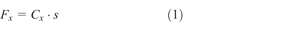
Tire typical relationship between force and slip rate shows that it has linear region and nonlinear region under different road adhesion conditions. When the tire slip rate is less than a certain value, the longitudinal force and slip rate behave as approximate linear relationship. 24 When the vehicle normally driving has slip rate rarely >2% in the linear region, therefore, the relationship between the force and slip rate can be defined as equation (1)
According to the definition of the slip rate and road surface adhesion, at the same time, the nonlinear relationship between the force and slip rate is ignored, and the tire longitudinal slip compensation formula is equation (2)

where
The vehicle steering model consists of 7 degrees of freedom (DOFs) as shown in Figure 1; 3 DOFs include longitudinal, lateral, and yawing motions, and 4 DOFs include the rotation of each wheel. Assuming that the front and rear wheel tracks are equal, and the left and right wheel steering angles are known, the center speed of the four wheels can be calculated as follows


where
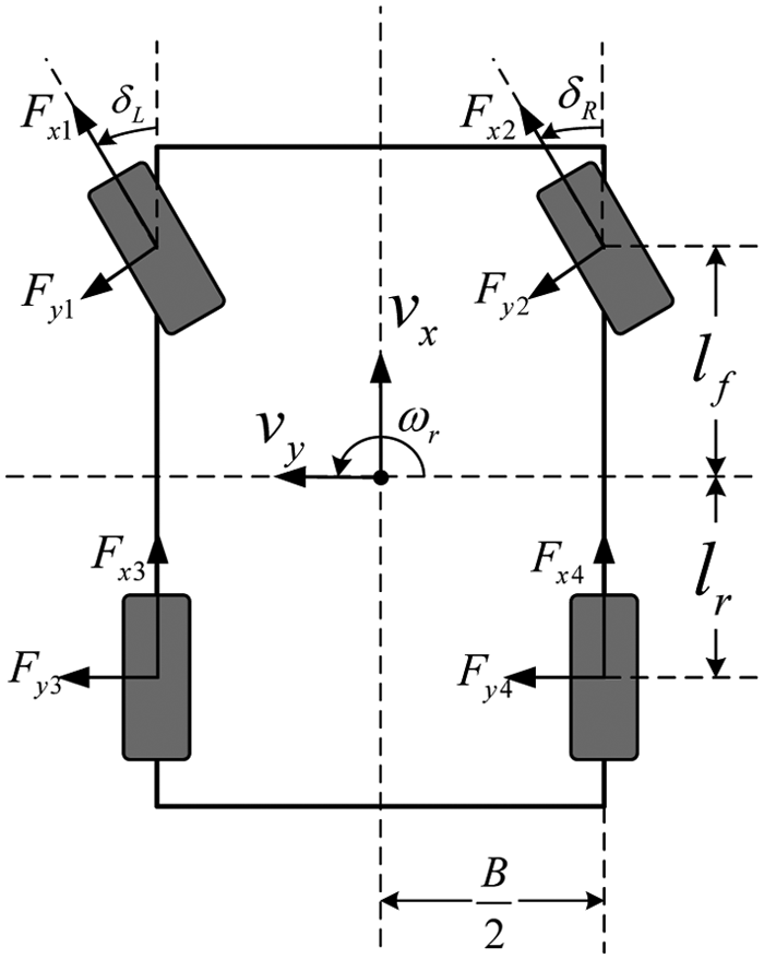
Four-wheel steering model of the vehicle.
The filtered center speed of wheels can be obtained by the above calculation. Then, stability factors are calculated by fuzzy rules based on the center speed of the wheels.
Judgment of the vehicle driving state
The accuracy of vehicle longitudinal velocity estimation is crucial to the judgment of the vehicle dynamic state. According to the characteristics in different working conditions, the vehicle driving states are divided into acceleration, deceleration, and sliding conditions, respectively, in view of various conditions to establish the credibility of the wheel speed based on fuzzy rules. Acceleration, deceleration, and sliding conditions in this article refer to the wheel acceleration and deceleration. It cannot be judged from the acceleration pedal and brake pedal simply but needed to be considered like speed of the four wheels, vehicle velocity, acceleration, and engine torque comprehensively.
The vehicle is in deceleration state if it can meet one of the following conditions:
A brake light signal (step the brake pedal);
The average speed of the four wheels is less than the longitudinal velocity, and the average wheel acceleration is less than the threshold;
The vehicle acceleration is less than the threshold;
More than two wheels are in the control of ABS.
The vehicle is in acceleration state if it can meet one of the following conditions:
The average speed of the wheel is greater than the longitudinal velocity, and the average wheel acceleration is greater than the threshold;
Torque is greater than the threshold, and the vehicle acceleration is greater than the threshold.
In addition, the vehicle is in sliding state if it can meet none of the above conditions.
The deceleration state is relatively more complex, and there is more intervention from ESC compared with the others. For example, for the intervention of ABS during the emergency brake, traction control system (TCS) will exert active braking force on the wheel to slow down the speed in accelerating when the drive wheels slipping, ESC will exert braking force on the wheel to change the yaw rate of the vehicle, and so on. Therefore, the change in the wheel speed is more complex during deceleration state, and there are higher requirements for the accuracy of the longitudinal velocity that should be paid more consideration.
Establishment of the fuzzy rules
The TSK-fuzzy model is proposed by Takagi, Sugeno, and Kang, 14 the fuzzy subset is regarded as input, and the output is precise value that can be directly used for further calculation. The typical fuzzy rule form of multiple input, single output (MISO) discrete system is equation (7)
where
Set the input vector
When defining the input signals, we should consider as much as possible of the parameters that describe the change in the wheel speed and the parameters that affect the change in the wheel speed. For example,
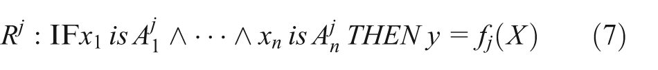
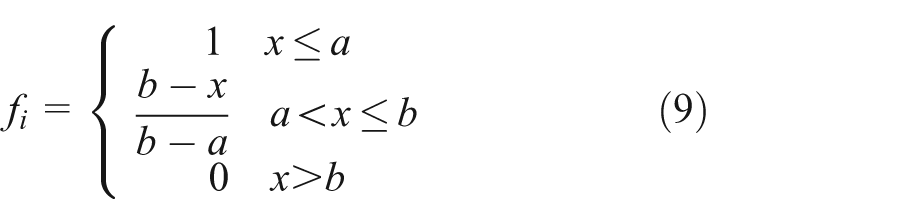
According to the difference of the fuzzy sets, the input signal is divided into four categories, which are fuzzy subset A, B, C, and D, as shown in Figure 2. Figure 2 shows the type of each fuzzy set, and the specific parameters are listed in the following tables. The selection of the domain of each fuzzy subset is based on a large number of experimental data, with calculation and appropriate amendments according to the results.
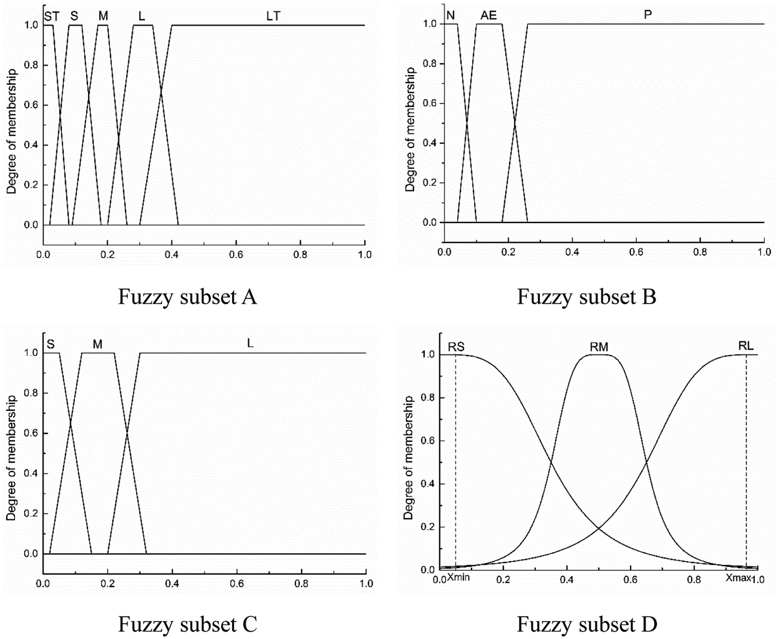
The membership function of fuzzy subsets.
The fuzzy subsets of the inputs such as


Variables for the fuzzy subset A.

ST: smallest; S: small; M: medium; L: large; LT: largest.
The fuzzy subsets of inputs such as
Variables for the fuzzy subset B.

N: negative; AE: approximately equal; P: positive.
The fuzzy subsets of inputs such as
Variables for the fuzzy subset C.
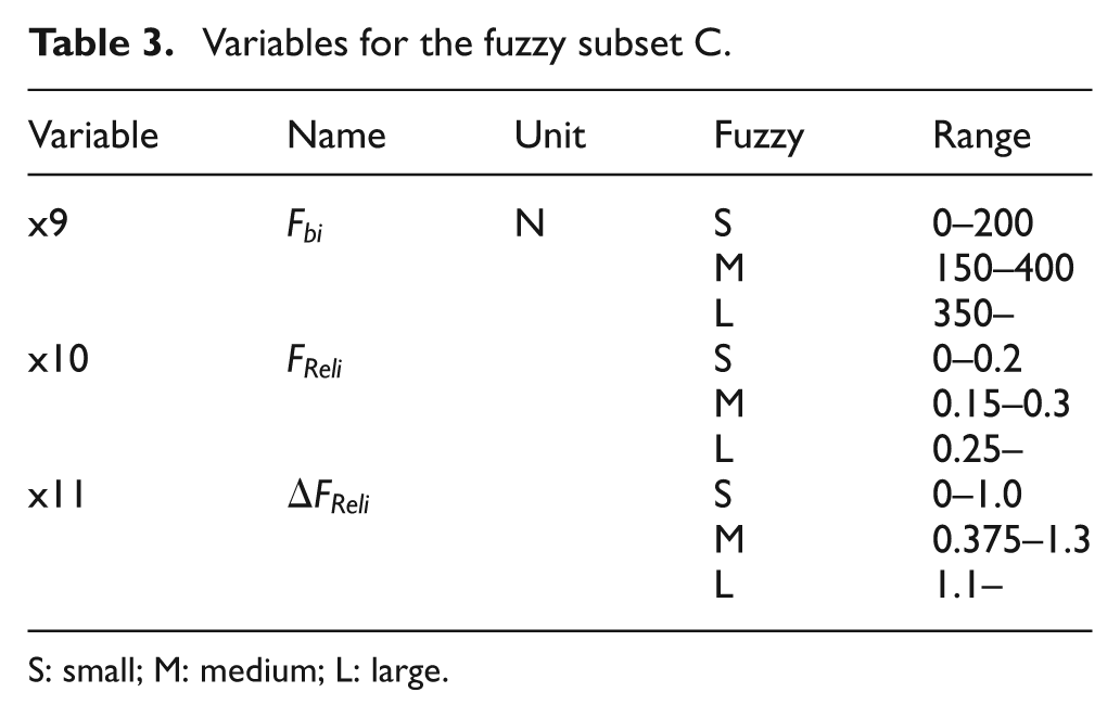
S: small; M: medium; L: large.
The proposed fuzzy rules which are used to estimate the vehicle longitudinal velocity are suitable for ESC system. The ESC will intervene when the vehicle is instable (such as wheel lockup, skid, oversteer, and understeer), for which there will be greater difference between the vehicle longitudinal velocity and speed of one or more wheels, that is, this wheel speed is incredible. So, we can judge whether the wheel speed is credible or not by the intervention of ESC. The
Variables for ESC intervention.
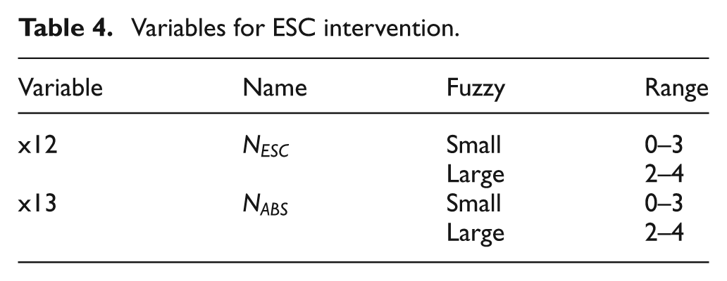
In addition, in order to increase the robustness and adaptability of fuzzy rules, the relative changes of the four wheels’ speed should be considered, and

The fuzzy rules of acceleration state are as follows
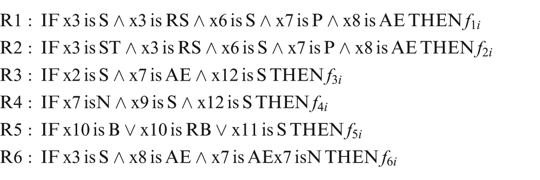
The fuzzy rules of sliding state are as follows
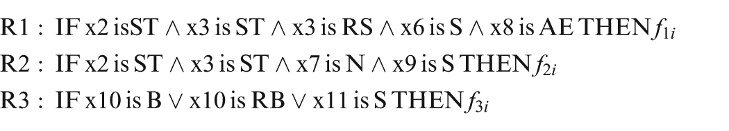
The fuzzy rules of deceleration state are as follows
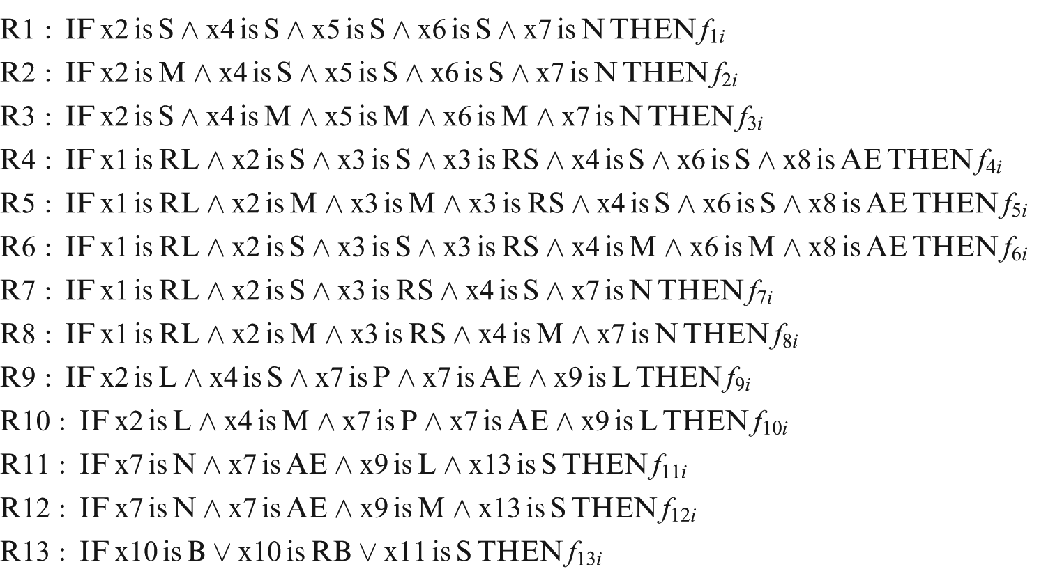
The above fuzzy rules are established based on the characteristics of the different driving states in different working conditions, but all the inputs are not considered in every rule. The use of the law can guarantee the accuracy of the calculation, reducing the amount of calculation at the maximum degree and improving real-time performance. For example, deceleration state rule R13 is judged according to the change in vertical force on the wheel lift.
What should be explained is that the fuzzy rules are aimed at a single wheel, and the true value of the gained membership degree aims at the corresponding wheel. The true value of the wheel speed credibility reflects the credible degree of the corresponding wheel speed, the same as the closeness of the wheel speed and the longitudinal velocity. The true value of the credibility is used by the estimation of the vehicle longitudinal velocity. Based on different conditions, the true value of the wheel speed reliability is calculated as follows

where m is the number of fuzzy rules and
Estimation of the longitudinal velocity
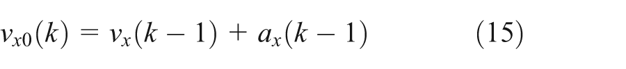
The vehicle longitudinal velocity and acceleration are estimated through the obtained credibility of the wheel speed. The basic formulas are as follows
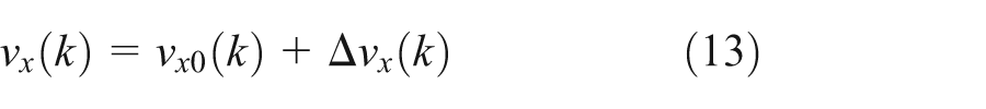

where
In order to reduce the calculation amount, only the credibility of the wheel speed is calculated at the speed stability of wheels, and the subsequent calculation is based on the credibility of the wheel speed. The membership degree
All the wheel speed signals are considered less credible, and all the wheels are instable if
where
The wheel speed signals are credible if

The vehicle longitudinal velocity can be estimated by the above formulas, and next, the correction of the vehicle longitudinal velocity and acceleration will be estimated by the fuzzy factors of wheel speed.
Correction of the longitudinal velocity
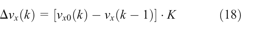
The correction of the vehicle longitudinal velocity and acceleration will be estimated by the fuzzy factors, and the formula is as follows
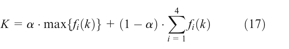
If the four wheels are under control of ABS, the coefficient K can be increased appropriately, but the coefficient K needed to be ensured less than 1.
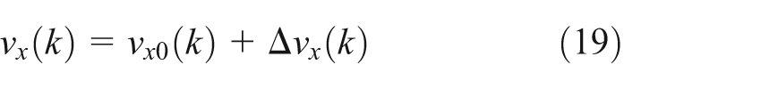
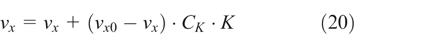
The correction of the vehicle longitudinal velocity is calculated as follows
Estimation of the acceleration
The estimation formula is as follows

where
Acceleration computation model formula is as follows

The correction of acceleration is calculated as follows

where
Test results and analysis
In this section, the longitudinal velocity estimation method will be validated by comparing longitudinal velocity with the four wheel speed signals. The tests data in this section come from ESC real vehicle test of a light-duty pickup truck with manual transmission. We convert the proposed method to C code and integration in the existing ESC system, compile and download to ECU, and at the same time install in the real car for test (Table 5).
Vehicle parameters.

The longitudinal velocity estimation method is aimed at the ESC, so it is applied to the vehicle ESC to verify its feasibility and robustness in this article. To validate whether the method is reasonable, the experiments should be carried out at the corresponding conditions. The wheels will not be locked and skid or in other extreme conditions during daily driving process; however, in this document, we are focusing on estimating the vehicle velocity in extreme conditions.
As shown in Figures 3 and 4, they are the curves of wheel speed signals during emergency brake when the vehicle is driving around the fixed radius circle in the counterclockwise direction. In Figure 3 we step on the brake pedal at 114.4s while the vehicle speed is 13m/s, and ABS works. The left side of the wheel speed fluctuation is quite great that is because the vehicle load shifts to the right when it runs in counterclockwise; therefore, the left side is easier to be locked. Figure 4 shows the wheel speed of the front axle on the left side and the longitudinal velocity, and it can be seen that the longitudinal velocity is smooth, and it does not change with the wheel speed fluctuations due to the intervention of ABS.

The wheel speed change curve in the process of the emergency brake.

The change in the wheel speed and the reference velocity curve in the process of the emergency brake.
Figure 5 presents the credibility of the corresponding wheel speed during emergency brake. According to the analysis, the left side of the wheel speed change is greater than the right when the vehicle is driving around the fixed radius circle in counterclockwise, so the left speed signal credibility should be lower than the right side. The credibility of the rear wheel speed signals should be greater than the front wheels because the intervention of ABS has great impact on the volatilities of the front wheels. The curves in Figure 5 are consistent with the previous analysis, and the feasibility of the proposed fuzzy rules is proved.
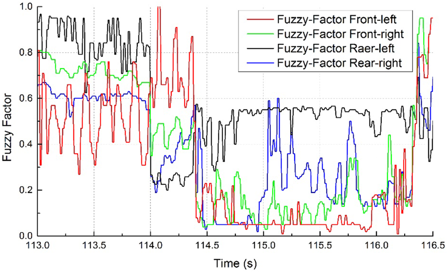
The credibility of the corresponding wheel speed of the emergency brake.
Figures 6 and 7 express the wheel speed and longitudinal velocity during the intervention of TCS when accelerating. In Figure 6, the rear wheel will slip in the process of accelerating from a standstill on the low adhesion road. The rear wheel speed will fluctuate for a force applied to the wheel to prevent wheel slip by TCS. Figure 7 describes the comparison of the left rear wheel speed and the longitudinal velocity, from which we can see that the longitudinal speed is smooth like the front wheel, and it does not change as speed fluctuations of the driving wheel due to the intervention of TCS. This conforms to the actual velocity change rule.
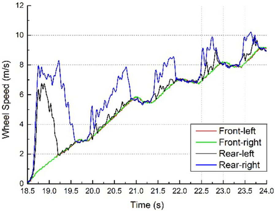
The wheel speed curve during the intervention of TCS.
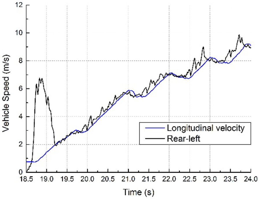
The wheel speed curve of the driving wheel and longitudinal velocity during the intervention of TCS.
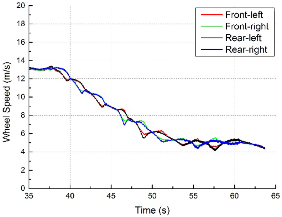
In Figures 8–10, the double-lane change test is carried out according to the ISO 3888-2 standard, and the change in steering angle is shown in Figure 8. All four wheel speed signals of lane change are shown in Figure 9, and it can be seen from this figure that the speed of the four wheels is not the same because of the steering and intervention of ESC, and the change in rear left wheel speed is particularly apparent for the intervention of ESC and tire sideslip. As we can see from this figure of tire sideslip that because the mass center position of the test vehicle is so high that it is easy to roll when the car rounds a turn.

The steering wheel angle of double-lane change test.

The four wheels’ speed of double-lane change test.

The wheel speed and reference velocity of double-lane change test during the intervention of ESC.
Figure 10 expresses the speed of the rear left wheel and the front right wheel as well as the longitudinal velocity, and it can be seen from this figure that the longitudinal velocity curve is smooth, and there is no fluctuation with the change in the wheel speed. Figure 11 shows the credibility of the wheel speed under the double-lane change test, and this also consists with the change in the actual wheel speed change. It can be seen from this figure that the credibility of the rear left wheel is smallest and can be considered unbelievable due to heavy fluctuation.
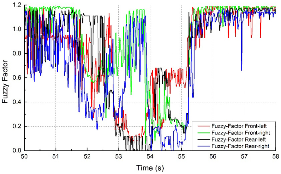
The credibility of the wheel speed of double-lane change test.
Figures 12–14 describe the results of pylon course slalom test. Figure 12 shows the change in the steering angle, and Figure 13 shows the wheel speed of the left rear, the right front, and the longitudinal velocity. It can be seen that all four speed signals are different and change with actual rotational angle of steering wheel; however, the longitudinal velocity is smooth, and it does not change with wheel speed fluctuations. This conforms to the actual velocity change rule.

The steering wheel angle of pylon course slalom test.
The four wheels’ speed of pylon course slalom test.

The wheel speed and reference velocity of pylon course slalom test.
In various ultimate conditions above, according to the ESC tests on real vehicle, no matter how severe the wheels fluctuate, we can always estimate the longitudinal velocity with the method, which is smooth and stable. The longitudinal velocity would not change wrongly with the wheel speed. To sum up, the algorithm mentioned in this article is feasible.
Conclusion
Based on the widely use of fuzzy logic in automotive engineering, 17 a longitudinal speed estimation algorithm is proposed. In this article, the vehicle driving states can be divided into three working conditions: acceleration, deceleration, and sliding based on the fuzzy rules. This article refers to three conditions, not the trampled accelerator, trampled decelerator, and hold accelerator, but the normal running and the ESC system intervenes are taken into account according to the change in the wheel speed, brake light signal, the thresholds, and so on. According to the characteristics of each working condition and the ESC intervention, the TSK-fuzzy rules are established to estimate the longitudinal velocity of vehicle. The experimental results show that the algorithm simplifies operation largely while keeping real time and improving the robustness. The results show that the method can assure the estimation accuracy through testing vehicle in practice under extreme driving situation, such as the brakes locked and skidded.
As a part of future work, we will continue the research in the following aspects: first, continue to do the real vehicle test to verify the algorithm which is used to estimate the wheels’ speed under various conditions; second, optimize the fuzzy rules and corresponding parameters and improve the efficiency of its operation in an embedded system; then, optimize the algorithm above of estimating acceleration and make it a fusion with the longitudinal acceleration sensor, improving its accuracy.
Footnotes
Appendix 1
Academic Editor: Ramoshweu Lebelo
Declaration of conflicting interests
The author(s) declared no potential conflicts of interest with respect to the research, authorship, and/or publication of this article.
Funding
The author(s) received no financial support for the research, authorship, and/or publication of this article.