
Abstract
The open and close duration, angle, and pressure of the intake and exhaust valves substantially influence compressed air engine efficiency and output power. In the actual prototype, the air distribution system can be of two types, cam air distribution type and rotary air distribution type. Compressed air engine based on the two types has been investigated. However, there have been debates over the advantages and disadvantages of these two technologies. The article aims to compare two technologies from the output power and energy efficiency. To verify theoretical analyses’ model, an experimental system is built to test the output power and efficiency of compressed air engine with cam air distribution system. It is shown that the output power of the compressed air engine with rotary air distribution system is higher than that of the compressed air engine with cam air distribution system. When the rotation speed is equal to 800 r/min, the output power of the compressed air engine with rotary air distribution system is about five times as much as that of the compressed air engine with cam air distribution system. The efficiency of two kinds of compressed air engines all declines with a rise in the rotation speed. Furthermore, the energy efficiency of the compressed air engine with rotary air distribution system is higher than that of the compressed air engine with cam air distribution system by approximately 10%. The analyses also indicate that sealing and lubrication are key to practical application of the compressed air engine with rotary air distribution system.
Introduction
A wide variety of renewable source technologies are needed to meet the challenges of sustainable energy development. 1 The air pollution has become a severe problem that influences the survival and development of humankind. 2 Because transportation accounts for a major share of global primary energy demand 3 and exhaust from internal combustion (IC) engines contributes largely to carbon emissions, 4 it is an urgent need to find alternative energy sources for engines with clean and environmentally friendly energy carrier. Some kinds of zero emission vehicles have been explored extensively. The battery electric vehicles offer high energy efficiency, allow energy diversification, enable load equalization of the power system, and operate quietly; 5 however, the heavy metal pollution, high initial cost, limited battery life, and long charging time have limited their development and application. 6 The superiority of hydrogen energy carrier is of high energy density; nevertheless, the lack of safety, energy efficient, and storage difficulties currently prevent the development of hydrogen-powered fuel cell vehicles. 7 Compressed air is a potential clean and environmental-friendly energy carrier. When the pressure and temperature of the compressed air are 30 MPa and 300 K, respectively, the energy density is close to that of the lithium battery. 8 Furthermore, the air tank can be completely refilled in a much less time than batteries, 9 and the price of compressed air engine (CAE) is relatively cheaper. 10
The feasibility of compressed air as a vehicular energy source has been researched. CY Huang et al. 11 created CAE by modified conventional IC engines. Motor Development International (MDI) 12 have developed airpod for transportation vehicle. A small air turbine with vaned-type rotor has been developed by BR Singh and O Singh. 13 A single screw expander working with compressed air was developed by W He et al. 14 And the influence of intake pressure on the performance was obtained. L Liu and X Yu 15 analyzed the feasibility and outlook of compressed air vehicles by thermodynamic analysis and experiment data. H Ibrahim et al. 16 introduced different energy storage techniques and their field of application. The energy stored in compressed air could be divided into transmission energy and expansion energy. The higher the air pressure, the larger the ratio of expansion energy. 17 The temperature of the compressed air decreases when the compressed air energy converts into mechanical work through CAE. It could be employed as heat sink to IC engines. A hybrid system consisting of a CAE and an IC engine was presented by Fang et al. 18 The exhaust waste heat from IC engine was used to heat the cylinder wall of CAE, which enhanced expansion energy and improved energy efficiency by approximately 15%. In addition, some scholars used compressed air to recover energy during braking to improve IC engine efficiency. Huang and Tzeng 19 demonstrated that the optimization of IC engine can increase the vehicle’s efficiency by approximately 18% with a hybrid pneumatic power system. But the hybrid pneumatic remains a limited resource and does not meet the zero pollution vehicle requirements. Compressed air as a vehicular energy which is applied in a vehicle has been verified. But the major disadvantage is that the CAE lacks running range because of low output power and energy efficiency. Thus, it is difficult to be widely accepted.
Air distribution system such as the open and close duration and angle of the intake and exhaust valves has a significant influence on CAE efficiency and output power. 20 Air distribution system of piston-type CAE has two types: the conventional crankshaft-driven cam distribution system and rotary distribution system. 4 Engines based on crankshaft-driven cam distribution system and rotary distribution system have been investigated and prototypes of two types of CAE have been modified. Rotary distribution system controls the timing sequence of the air flowing in and out using rotation of the shaft. Cam distribution system uses the cam mechanism for driving the intake and exhaust valves which control the timing sequence of the air flowing in and out of the engine.
However, there has been much debate about the advantages and disadvantages of the two technologies. For example, the conventional cam mechanical valve can ensure smooth running and fast response, but the open-and-close response is slow during operation which causes energy loss during intake and exhaust process. The rotary distribution system has a quick open-and-close response during operation, but the leakage under high air supply pressure is difficult to overcome. This article aims to compare the two kinds of compressed air distribution system. Air power will be used to evaluate the compressed air energy efficiency. The comparison will be based on the output power, torque, and efficiency. Theoretical analyses and experiment are carried out in this work. The following sections are organized as follows: first, the air distribution systems of CAE are briefly introduced in section “Description of the air distribution systems.” Second, theoretical analyses’ energy conversion in CAE system is carried out in section “Energy conversion in CAE system.” To verify theoretical analyses, the experiment is built in section “Experimental verification.” The performance comparison of the two kinds of CAE is implemented based on theoretical analyses in section “Performance of the two kinds of CAEs.” Finally, the conclusions are summarized in section “Conclusion.”
Description of the air distribution systems
Typical cam mechanical and rotary distribution systems are shown in Figure 1(a) and (b), respectively. For cam mechanical system, the cam lift follows the cam profile when appropriate springs are used. 21 This means that the motion of the valve is controlled by the cam profile and the valve moment is stable. The principle of cam mechanical distribution system is described as follows: The cam is mounted on the camshaft 2 which is driven by crankshaft using pulley wheel 1. The intake valve 8 and exhaust valve 11 opened or closed are depended on the boundary shape of the cam profile. When the intake valve 11 is opened, the pressurized air flows into cylinder by intake port 11. Since the compressed air in the air passage acts on the intake valve 11 surface A and B, as indicated by the red arrows, the net force should be zero, and thus the valve should be pressure compensated.

Cross section of the air distribution system: (a) cam mechanical system and (b) rotary mechanical system.
The detail about the principle of rotary distribution system is described in the literature. 4 The intake and exhaust valves open and close instantly when the air passage is connected by the channel in air distribution shaft.
Energy conversion in CAE system
A typical piston-type CAE system is shown schematically in Figure 2. The principle of the compressed air power system converts the compressed air energy into mechanical work through the CAE. To achieve high energy density, the storage pressure inside the compressed air tank reaches to several hundred standard atmosphere. However, the pressure air-powered engine is operated at several standard atmosphere. So the regulator is installed between the compressed air tank and CAE. The pressure is reduced from several hundred to several standard atmosphere by the regulator. The process results in more than 40% energy loss. The air distribution system which controls the flow of air into and out the engine is critical to improve CAE performance. Note that only air distribution system is carried out in this work.

Schematic diagram of the engine system.
Air power
In this section, air power as an energy consumption evaluation criterion of pneumatic system is briefly introduced. Air power as the flux of the available energy that can be extracted from flowing air undergoes a reversible process from a given state to the atmospheric state. According to the literature, 17 air power is expressed as

From equation (1), air power is proportional to flow rate. Figure 3 shows that the air power is related to the pressure of the compressed air that increases from 0.1013 to 3 MPa; when the mass flow rate is 0.1 kg/s, the temperature of air is 293 K. The increase in the air power from 0 to 28 kW indicates that to obtain a higher power, higher intake pressure is necessary, which accordingly results in more complicated air distribution system.

Air power versus air pressure.
Intake process
According to the pressure before and after the intake valve, the mass flow rate is calculated as follows

where


The value of b, the critical pressure ratio of the throttle valve, is 0.49. The cylinder pressure during the intake process can be calculated using the equation of state for ideal gas which can be written as follows

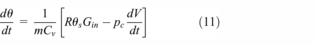
The temperature differential can be calculated by solving the energy equation. For an open system, the increase in internal energy equals to the sum of the heat, the enthalpy supplied to the system, and the work. Accordingly, the energy balance is written by

The intake process proceeds very quickly so that the process can be considered adiabatic

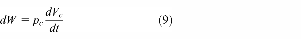
The work can be calculated by
The enthalpy supplied to the system is

Substituting equations (8) and (10) into equation (7) yields
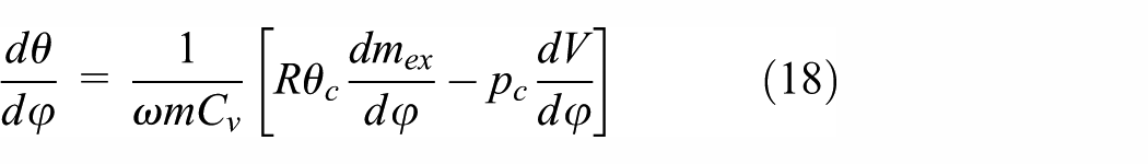
For piston-type CAE, the crank angle can be yielded by equation (12)

Substituting equation (12) into equations (2) and (11) yields


According to equations (13) and (14), the air mass flow and the cylinder temperature are inversely proportional to the rotation speed during the intake process.
Expand process
In the actual process, the heat exchange with the exterior is difficult in high rotation speed. So the process of expansion can be considered as isentropic processes. The pressure and temperature of the expand stroke can be calculated by the following formula


Exhaust process
Referring to the intake process, the air mass flow and cylinder temperature of the exhaust process can be calculated by the following formulas

Energy conversion and efficiency
Assuming that there is no friction and air leak during the working process, the ideal scenario for performing the maximum level of mechanical work for the CAE is described as follows:
Intake stroke: the intake valve opens quickly and the cylinder pressure quickly reaches supply pressure. The piston is pushed from the position of intake valve open to that of intake valve close at a constant pressure of Ps in a quasi-static process.
Expand stroke: the compressed air inside the cylinder expands until the pressure reaches the atmospheric state. During this process, the air state change is considered isothermal.
Exhaust stroke: exhaust valve opens and pulls back the piston from the position of exhaust valve open to that of exhaust valve close in a quasi-static process.
However, in the actual process, the above working process is difficult to achieve. The energy loss occurs in intake stroke, expand stroke, and exhaust stroke. The state changes for an actual process and an ideal process are depicted by the p–V diagram in Figure 4. A-B-C-D represents the ideal working process and the area ABCD represents the maximum output work. A-B′-C′-D′ represents the actual working process and the area AB′C′D′ represents the actual output mechanical work. In addition, the intake stroke energy loss can be expressed by the areas ABB′ and B′CC′, the expand stroke energy loss is described by the arc area C′D′, and the area AD′D represents the exhaust stroke energy loss.

The p–V diagram.
According to equation (19), the efficiency is the ratio of the actual output mechanical work and the ideal output work in one period. The numerator is the output power during engine operation and the denominator is the air power during operation. The efficiency can be calculated as

where Pme is the output power and Pap is the air power.
According to Figure 4, to improve the CAE efficiency, we must reduce intake stroke energy loss, exhaust stroke energy loss, and expand stroke energy loss. Increasing heat exchange area and heat transfer coefficient can enhance heat absorbed by the air from outside. The air distribution system is critical to improve the CAE efficiency.
For cam mechanical distribution system, because the cam controls the valvetrain by its profile, it must avoid unnecessary dynamic force fluctuation. 22 So higher degree polynomial is introduced by most cam shape functions. The cam shape function controls the intake valves and exhaust valves on the basis of higher degree polynomial which is illustrated by the following equation

where hv(x) is the cam lift, and x = a/aB; a is the cam angle and aB is the half wrap angle. In practical prototype, the half wrap angle is equal to 45°.
So the open-and-close response of the valve is not fast enough. However, the dynamic force fluctuation is not considered in rotary air distribution system. The effective sectional area of rotary air distribution system is shown in Figure 5. Taking intake valve as an example, the effective sectional area can be calculated by the following formulas

where


where d1 is the diameter of intake port and d2 is the diameter of exhaust port.

The schematic of effective cross-sectional area.
Assuming that the effective cross-sectional area of rotary passage is bigger than that of the intake and exhaust passages, according to equations (21)–(25), the valve opening areas can be illustrated as in Figure 6.

Valve opening areas using cam and rotary air distribution systems.
Figure 6 shows that compared with cam air distribution system, the intake valve and exhaust valve open and close instantly using rotary air distribution system. The mathematical details about cam air distribution CAE can be referred to in previous literatures.20,23 The p–V diagram (Figure 7) shows that the working process with rotary air distribution system is more close to the ideal working process when the rotation speed and the supply pressure are 600 r/min and 2 MPa, respectively.

Theoretical p–V diagram (at 600 r/min) for two kinds of air distribution system.
The p–V diagram area indicates output power. It is obvious that the output work of the rotary air distribution system is higher than cam air distribution system. The cylinder pressure is lower than the supply pressure because of the small effective cross-sectional area during intake.
Experimental verification
Experiment setup
In this article, a 500-cm3 two-stroke CAE was designed as in a previous study.24–27 The output performance and fluid characteristics of the CAE, which used high-pressure compressed air as the driving energy source, were measured. A high-pressure air system was integrated with a 35-MPa air compressor (BAUER 680; CompAir, Schrobenhausen, Germany). To adjust supply pressure, high-pressure regulator (TESCOM 44-1300, Minnesota, American) and low-pressure regulator (TESCOM 44-2200, Minnesota, American) were arranged. The compressed air was stored in a 300-L air tank. To provide a steady airflow rate, 300-L buffer tank was used. The test bench included a 100-N m torque transducer coupled with an electromagnetic brake, used for measuring the test engine output power. The electromagnetic brake applied a load between 0 and 100 N m. Two pressure sensors and two thermocouples were installed at the engine inlet and outlet, respectively, to measure the pressure and temperature variations. For precise measurement of dynamic cylinder pressure variations, Kistler 4075A precision pressure sensor was used. The sensor operating temperature ranges from −20 to 50, and natural frequency is approximately 150 kHz. A high-pressure digital vortex flow meter (DY015; Yokogawa Electric Corp., Tokyo, Japan) was installed at the engine inlet to record flow rates. All data during the experiments were transferred to a data acquisition unit (PCI1716; Advantech Co. Ltd, Taipei, Taiwan) for recording and further analysis. The output power was calculated as the product of the measure torque and rotational speeds. The flow rate, supply pressure, and temperature were recorded by data acquisition unit; the air power can be calculated by equation (1).
Figure 8 shows a schematic overview of the CAE test bench. The prototypes of CAE using cam air distribution system are shown in Figure 9. Table 1 depicts the main parameters of the prototype.

Experimental setup of CAE test bench.

The prototype of CAE using cam air distribution system.
Prototype geometrical specifications.

Results’ analyses
The output power and energy efficiency are important factors in the application of the CAE. The output power and energy efficiency are obtained by the above experimental platform. The supply pressure is set at 2 MPa, and the rotation speed ranges between 300 and 800 r/min. The curves of output power and energy efficiency variation at different rotation speeds are shown in Figure 10(a) and (b), respectively.

(a) Output power and (b) energy efficiency at different rotation speeds.
From Figure 10, it can be seen that
The theoretical analyses’ model is verified, and the experimental results have similar trend with the simulation results. The output power curves have maximum value, and the efficiency curves decrease with the increase in the rotation speed.
In the first instance, the output power increases with an increase in the rotation speed; when the output power reaches the maximum value, the output power declines with an increase in the rotation speed. The highest output power values of the simulation and experiment are 1.92 and 2.2 kW, respectively.
The main reason is that when the engine speed is smaller than the certain speed, the output power is mainly affected by the rotation speed. When the engine is larger than the certain speed, the output power is chiefly influenced by the output torque. The errors between the experimental and simulation results are the fluctuation of the supply pressure, leakage during operation, the fluctuation of the friction coefficient which is influenced by cylinder temperature, and lubrication element which is not considered in simulation model.
The supply pressure during the experiment is shown in Figure 11. The supply pressure fluctuates in the near-setting supply pressure because the supply airflow is insufficient to the demand airflow.

Experimental and simulation curves of the supply pressure.
Performance of the two kinds of CAEs
In section “Experimental verification,” the theoretical analyses’ model was verified using a prototype with cam air distribution system. In this part, the output power, energy efficiency, and leakage of the two kinds of CAEs are studied by theoretical analyses’ model. The basic parameters of the two kinds of CAEs are shown in Table 2.
Basic parameters.

Besides the above basic parameters, the geometrical specifications of cylinder are shown in Table 1. The pressure of supply air is set at 2 MPa. At different rotation speeds, the simulations of the output power and energy efficiency of the two kinds of CAEs are done, and the results are shown in Figure 12.

The output power and energy efficiency of the two kinds of the CAEs: (a) power versus speed and (b) efficiency versus speed.
Figure 12(a) illustrates the relationship between the output power and the rotation speed. As can be seen, the curve of the output power of the CAE with rotary air distribution system is higher than that of the CAE with cam air distribution system. The output power of the two kinds of CAE has different changing trend with an increase in the rotation speed. Furthermore, when the rotation speed is equal to 800 r/min, the output power of the CAE with rotary air distribution system is about five times as much as that of the CAE with cam air distribution system.
Figure 12(b) shows the relationship between the energy efficiency and the rotation speed. It can be seen from Figure 12(b) that the energy efficiency of the two kinds of CAEs all declines with a rise in the rotation speed. Furthermore, the energy efficiency of the CAE with rotary air distribution system is higher than that of the CAE with cam air distribution system by approximately 10%.
It is obvious that the output power and energy efficiency of CAE with rotary air distribution system are far better than that of the CAE with cam air distribution system. However, it is difficult to solve sealing and lubrication problems in rotary air distribution system, especially in high supply pressure and high speed. So the leakage may influence the CAE with rotary air distribution system performance. In comparison, the cam air distribution sealing and lubrication are easily achieved by modifying conventional cam system.
Conclusion
In this article, simulation and experimental studies of the CAE with cam air distribution system are done. Two types of air distribution system for CAE are compared in terms of output power and energy efficiency, and the conclusions are summarized as follows:
Given the pressure of supply air, the output power of the CAE with rotary air distribution system is higher than that of the CAE with cam air distribution system. When the rotation speed is equal to 800 r/min, the output power of the CAE with rotary air distribution system is about five times as much as that of the CAE with cam air distribution system.
The efficiency of two kinds of CAEs all declines with the increase in the rotation speed. Furthermore, the energy efficiency of the CAE with rotary air distribution system is higher than that of the CAE with cam air distribution system by approximately 10%.
Although the rotary air distribution system has advantages for enhancing the output power and energy efficiency, it also has some disadvantages, for example, sealing and lubrication which may become bottleneck for the CAE with rotary air distribution system.
Footnotes
Appendix 1
Academic Editor: Francesco Massi
Declaration of conflicting interests
The author(s) declared no potential conflicts of interest with respect to the research, authorship, and/or publication of this article.
Funding
The author(s) disclosed receipt of the following financial support for the research, authorship, and/or publication of this article: The research work presented in this article was financially supported by the National Natural Science Foundation of China (grant nos 51375028, 51605013, 51675020).