
Abstract
In this article, the nonlinear finite-element analysis software LS-DYNA is used to study the crashworthiness of functionally graded thickness circular tubes under multiple loading angles (0°, 10°, 20°, 30°, and 40°). The specific energy absorption (SEA) and maximum crashing force (
Introduction
Train, automobile, and large ship collisions have not only caused great economic losses but have also posed a serious threat to the safety of passengers. As an efficient energy-absorbing structure, the thin-walled structure has been widely used in automobiles, ships, aircraft, and other vehicles. This structure can absorb most of the impact energy from collisions through plastic deformation. In recent years, the crashworthiness characteristics of different forms of thin-walled structures, such as circular, square, foam-filled and windowed, 1 and surface-grooved tubes, have been analyzed in detail. Due to its high strength, low weight, and good manufacturing process, aluminum tubes are widely used in energy-absorption (EA) devices.
In the collision process, thin-walled structures not only bear axial load but can also be subjected to oblique loads of different angles. Under oblique loading, the EA characteristics of thin-walled tubes decrease sharply, and the combined mode of axial progressive and global buckling is produced. Compared to axial progressive collapse, the global buckling mode is unstable. Therefore, the design of thin-walled structures that can absorb more energy and produce a stable deformation under oblique load has attracted more attention. Gao et al. 2 investigated the crashworthiness of thin-walled structures with different shapes under oblique load. Tarlochan et al. 3 studied the crashworthiness of thin-walled structures with different cross-sectional shapes under axial and oblique loading. Ahmad et al. 4 found that conical tubes exhibit good crashworthiness under oblique load. These thin-walled structures have the same wall thickness, but their inherent weakness is that they are not able to make full use of the material to meet the requirements for lighter weight. 5 Therefore, it is widely considered that a new structure with varying thicknesses should be used to improve material usage. Tailor rolling blanks (TRBs), which lead to a continuous thickness variation in a workpiece, have been developed in recent years. 6 TRB technology can realize the continuous change of the thickness of the structure and obtain the ideal stiffness. Compared with the traditional uniform thickness of thin-walled tubes, functionally graded thickness (FGT) structures can provide more control of crashworthiness.
Sun et al. 7 used a finite-element (FE) model to study the crashworthiness of a functionally graded thin-walled square tube under axial impact and found that the impact behavior of the functionally graded tube is better than a uniform-thickness tube. Zhang and Zhang 8 carried out experimental and numerical studies on the impact characteristics of tapered tubes with variable thickness under axial load. Xu et al. 9 carried out experimental studies on the crashworthiness of thin-walled structures with FGT. Xu 10 found that FGT tubes had the advantage of reducing the initial peak force and improving EA compared to circular and conical tubes of uniform thickness. Li et al. 11 investigated the crashworthiness of circular tubes with FGT under axial and oblique impact using the FE method and found that the FGT tube had better EA performance than a conical tube under oblique loading. Li et al. 12 studied the impact characteristics of hollow and foam-filled thin-walled structures under multiple loading angles. Zhang et al. 13 investigated the axial impact characteristics of double functionally graded tubes and found that it possessed great EA characteristics. Baykasoglu and colleagues14,15 studied the axial impact characteristics of functionally graded aluminum tubes and optimized their length-to-diameter (LD) ratio and thickness gradient. Xu 16 analyzed the axial impact characteristics of an FGT tube and optimized its length, diameter, and gradient index.
Based on the above-mentioned research, many scholars have analyzed the impact crashworthiness of FGT circular tubes. However, the effect of the LD ratio and thickness gradient index on the crashworthiness of FGT tubes under oblique impact load has not been studied thoroughly. This article mainly studies the crashworthiness of FGT tubes under axial and oblique impact load and analyzes the effect of the LD ratio and thickness gradient index P on crashworthiness and EA characteristics of FGT circular tubes. The results show that the two parameters of FGT tubes have a greater influence on crashworthiness characteristics. The response surface method is used to construct the surrogate model of the integrated SEA
Numerical modeling
Geometric model
The thickness of the FGT tube in this study is changed along the axial direction, and the thickness of each position is described as equation (1), where x is the distance from the collision end of the tube, L the length of the circular tube, and P the thickness gradient index. The change in the value of P can control the thickness distribution in the tube. Under the action of the thickness gradient index P, the thickness of the tube changes continuously in the axial direction, and the convexity and concavity of the thickness function also change. As can be seen from Figure 1, when P < 1, the thickness gradient function is convex; when P > 1, the thickness gradient function is concave. The ideal deformation mode of a thin-walled tube is axial progressive crushing from the collision end to the other end. Therefore, the thickness of the tube at the collision end is

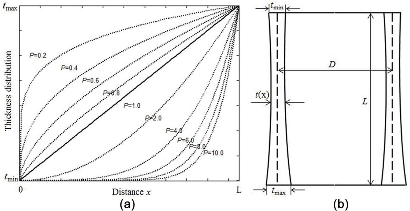
Schematic diagram of thickness distributions t(x) versus distance.
FE modeling
The FE model of the FGT tube was established using the FE preprocessing software HyperMesh; the FE model is shown in Figure 2. The tube is meshed with Belytschko–Tsay four-node shell elements. Convergence testing shows that the shell elements with dimension of 2.5 mm × 2.5 mm can predict the crushing behavior of an FGT tube. 13 The nonlinear explicit FE solver LS-DYNA is used to simulate the FGT tube under oblique impact. An automatic single contact is chosen to simulate the contact of the circular tube itself, and the static and dynamic coefficients of friction are set as 0.3 and 0.2, respectively. One end node of the tube is constrained by 6 degrees of freedom, and the rigid wall is defined by the keyword *rigidwall_planar_moving.
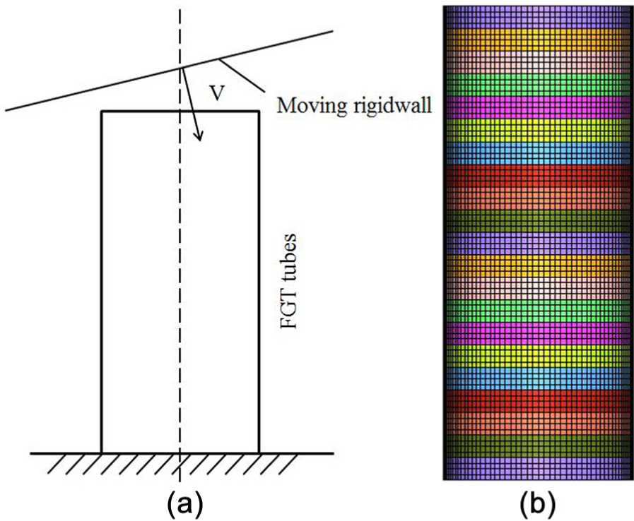
Schematic diagram of oblique impact simulation.
The tube wall is made of aluminum alloy (AA6060-T4) with density
In order to simulate oblique impact scenario of the circular tube, the tube is impacted by a 250-kg rigid wall with a velocity of 10 m/s, and the angle between the normal direction of rigid wall and the tube is

Validation of the FE model
In order to verify the correctness of the FE model, the FE results of the average impact force (

where
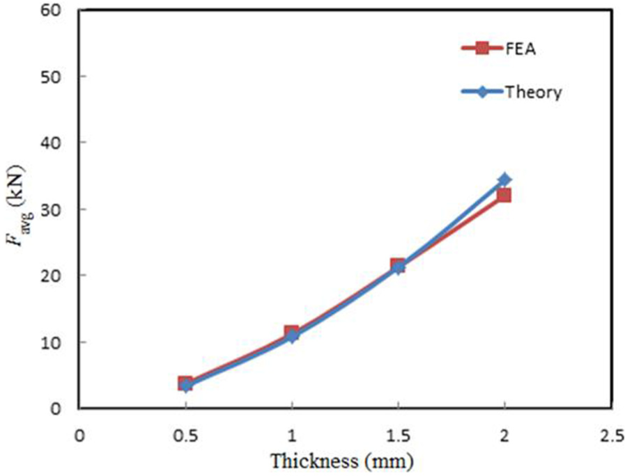
Comparison between FE results and the theoretical formula.
In order to verify the FGT tube FE model, the FE calculation results and the test results from the literature
10
were compared. The material and dimension parameters of the FGT tube are from the literature.
10
The material of the FGT tube is AA6061-T5, while L = 210 mm, D = 45 mm,

Comparison of numerical and experimental results 10 for the FGT circular tube.
Numerical analysis
Structural crashworthiness criteria
The typical force–displacement curve of the FGT circular tube under axial impact is shown in Figure 5. In order to evaluate the EA characteristics of FGT circular tubes under oblique impact loading, the EA, maximum impact force (

where

where M is the mass of the energy-absorbing structure. The SEA in this case is greater, and the EA characteristics of the thin-walled structure are better.

Typical force versus displacement of FGT tubes.
In this study, in order to consider the load uncertainty and the crashworthiness of the FGT circular tube under axial and oblique loading comprehensively, the

where
Parameter influence analysis
Effect of LD ratio
In order to study the influence of different LD ratios on the EA of FGT tubes under different impact angles, the thickness gradient index P is set to 1 and the LD ratio is set to 2.0, 2.5, 3.0, 3.5, and 4.0. The length of the FGT tube is fixed at 210 mm. The effect of five different LD ratios on the crashworthiness of FGT tubes under different angles is shown in Figure 6. As can be seen from this figure, with increasing impact angle, the absorption energy and SEA of the FGT circular tube are decreased. Under large impact angle, the EA and SEA of the FGT tube are drastically reduced because the FGT tube undergoes a global buckling deformation under large angle. The EA decreases with increasing LD ratio, and the SEA increases with increasing LD ratio. It can be seen that the tube with a large LD ratio has a relatively small EA but a relatively high SEA because of its relatively small mass. It can be seen from Figure 6(c) that the maximum crashing force of the FGT tube exhibits a decreasing trend with the increasing impact angle and LD ratio. At a large impact angle (

Comparison of (a) energy absorption, (b) specific energy absorption, and (c) maximum crashing force for different LD ratio values with increasing load angle.
Effect of thickness gradient index
In order to study the influence of different thickness gradient indices on the EA of FGT tubes under different impact angles, the LD ratio is set to 2.5 and the thickness gradient indices are set to 0.2, 0.4, 0.6, 0.8, 2.0, 4.0, 6.0, 8.0, and 10.0. The effect of 10 different thickness gradient indices on the crashworthiness of FGT tubes under different angles is shown in Figure 7. As can be seen from this figure, the absorption energy and SEA of the FGT circular tube dramatically decrease with increasing impact angle, and the maximum crashing force exhibits a decreasing trend. It can be seen from Figure 7(a) and (b) that with increasing thickness gradient index, the absorption energy decreases, and the SEA exhibits a decreasing trend. When the thickness gradient P < 1, the EA and SEA of the FGT tube are obviously larger than P > 1 because the FGT circular tube’s section thickness gradient function is convex when P < 1, and the corresponding mass of the circular tube is larger than the P > 1. However, a smaller thickness gradient P of FGT circular tubes does not result in a larger SEA. For example, there is almost no difference in the SEA of the FGT circular tube between thickness gradient P of 0.6 and 0.8, and the SEA with a thickness gradient P of 4.0 is larger than that of 2.0. It can be seen from Figure 7(c) that the maximum crashing force of the FGT tube shows a decreasing trend with increasing impact angle and thickness gradient index.

Comparison of (a) energy absorption, (b) specific energy absorption, and (c) maximum crashing force for different P values with increasing load angle.
Multiobjective optimization
Experimental design
A full factorial experiment is used in determining the two design variables of the FGT circular tube. The thickness gradient index P is selected as 0.2, 0.4, 0.6, 0.8, 1.0, 2.0, 4.0, 6.0, 8.0, and 10.0, and the LD ratio as 2.0, 2.5, 3.0, 3.5, and 4.0, and 50 tests are designed. Since the SEA and maximum crashing force are significantly different when the gradient index P < 1 and P > 1, and the FGT tube is more efficient in increasing SEA values when
Experimental design and numerical results.

LD: length-to-diameter.
In order to analyze the influence of the LD ratio and the thickness gradient index of the design variables on the response, the results of the main effect test are analyzed. The main effect analysis does not consider the influence of other design variables and analyzes the influence of a design variable on the response. The greater the absolute value of the main effect, the greater the influence of the design variable on the response. The main effect analysis results are shown in Table 2. It can be seen from this table, in the case of
Main effect analysis.

LD: length-to-diameter.
Surrogate model
Based on the results of the full factorial experiment, an approximate model of the integrated SEA and maximum crashing force is constructed based on the response surface method. Figure 8 shows the response surface of the integrated SEA and the maximum crashing force at various values of the LD ratio and thickness gradient index. It can be seen from this figure that the integrated SEA of the FGT tube decreases with increasing gradient index and increases with increasing LD ratio when 0 < P ⩽ 1. The maximum crashing force first decreases and then increases with increasing thickness gradient index P and decreases with increasing aspect ratio. The integrated SEA of the FGT tube increases with increasing LD ratio when 1 < P ⩽ 10 and decreases with increasing P. The maximum crashing force decreases with increasing LD ratio and decreases with increasing P. The integrated SEA and maximum crashing force are expressed in equations (7) and (8)


Approximated response surfaces of
In order to evaluate the accuracy of the surrogate model, the RE, root-mean-square error (RMSE), maximum absolute error (MAX), and R2 values 17 are selected to evaluate the error between the response value and the FE numerical calculation. The expression of each error analysis is given by equations (9)–(12), respectively


where n is the number of design sample points, and
The surrogate model error analysis is shown in Table 3. As can be seen from this table, the surrogate model has high precision, which can be carried forward in the subsequent optimization design.
Accuracies of the surrogate model.

RMSE: root-mean-square error; MAX: maximum absolute error; RE: relative error.
Multiobjective optimization
Optimization techniques
After using the response surface method to construct the surrogate model of the integrated SEA and maximum crashing force of the FGT circular tube, an optimization algorithm is needed to optimize the agent model. In this article, a nondominated sorting genetic algorithm II (NSGA-II) with elitist strategy is used to solve the multiobjective optimization problem; the optimal mathematical model can be described as

When the genetic algorithm is used to solve for the maximum and minimum values of the surrogate model, an initial population is randomly generated to encode the individual population, and the objective function is transformed into a fitness function; each individual is assessed for fitness, and the degree of merit of each individual is also assessed. The selection, crossover, and mutation algorithms are then selected to produce a better new-generation population. Finally, the termination conditions are judged. This genetic algorithm optimization process is illustrated in Figure 9, and the specific parameters of the surrogate model used in this article are shown in Table 4.

Genetic algorithm optimization flowchart.
NSGA-II algorithm parameters.

Optimization results
In order to verify the correctness of the FE model, this article studies the minimum and maximum impact forces that the structure can achieve under specific constraints. For

Pareto-front solutions from the NSGA-II algorithm: (a)
Optimization results of minimizing
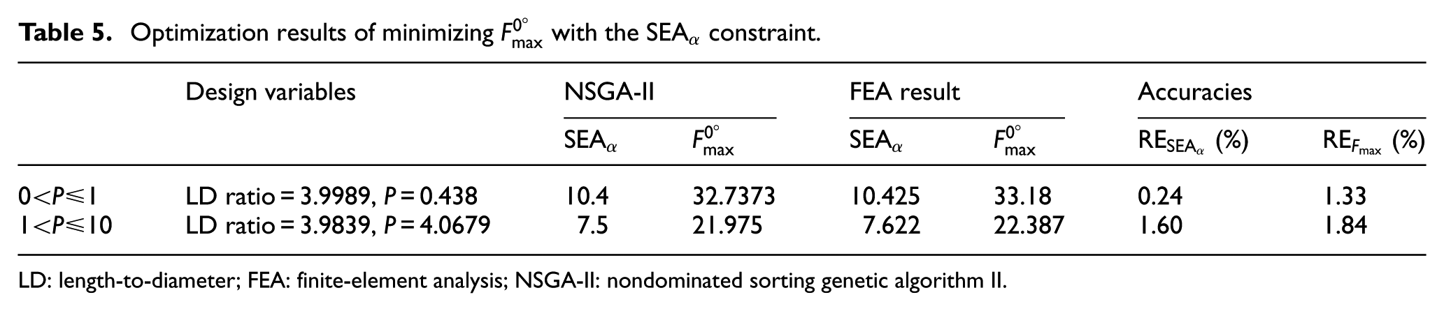
LD: length-to-diameter; FEA: finite-element analysis; NSGA-II: nondominated sorting genetic algorithm II.
Conclusion
The crashworthiness characteristics of an FGT circular tube under axial and oblique loading were studied in this article. Taking the EA, SEA, and maximum impact force as the main indices, the influence of the variable thickness gradient index P and LD ratio on the EA characteristics of an FGT circular tube under different loading angles was analyzed. The response surface method was used to construct a surrogate model of the integrated SEA and the maximum impact force, and the genetic algorithm was applied to optimize the agent model. The main conclusions of this study are summarized as follows:
The SEA decreases with increasing thickness gradient index and exhibits an increasing tendency with increasing LD ratio. The maximum impact force shows a decreasing trend with increasing thickness gradient index and LD ratio. A thickness gradient index in the range of
In the case of
In order to maximize the integrated SEA and minimize the maximum crashing force, the NSGA-II was used to optimize the FGT tube, and the Pareto-front solution is obtained. The errors of the integrated SEA and the maximum impact force are within 5%, which verifies the accuracy and effectiveness of the optimization method.
Footnotes
Acknowledgements
Academic Editor: Mario L Ferrari
Declaration of conflicting interests
The author(s) declared no potential conflicts of interest with respect to the research, authorship, and/or publication of this article.
Funding
The author(s) disclosed receipt of the following financial support for the research, authorship, and/or publication of this article: This work was supported by the National Support Program of China (grant nos 2015BAG12B01 and 2015BAG13B01-05), the National Natural Science Foundation of China (grant nos U1334208, 51675537, and 51405516), and the Independent Exploration and Innovation Program of Central South University (grant no. 2016zzts336).