
Abstract
This study numerically investigates the effects of changing vaned diffuser angles and vaneless diffuser widths of a two-stage centrifugal refrigerant compressor on the reduction of surge flow rate and the improvement of part-load performance. The first stage has a low-solidity vaned diffuser, while the second stage has a vaneless diffuser. The analysis results show that adjusting the angle of low-solidity vaned diffuser in the first stage can lower the surge flow rate and keeps high efficiencies at low flow rates. The inlet guide vane of the first stage can also lower the surge flow rate; however, their simultaneous actuation cannot lower the surge flow rate further. Reducing the vaneless diffuser width of the second stage can lower the surge flow rate. Meanwhile, simultaneously adjusting the individual inlet guide vanes of the second stage can also effectively lower the surge flow rate. If the diffuser width of the first stage is reduced while the low-solidity vaned diffuser blade angle is fixed, the surge flow rate will be lowered obviously as the inlet guide vane is adjusted. However, reduction in diffuser width decreases the efficiency at low flow rate. Controlling the inlet guide vane and diffuser width well can lower the surge flow rate to 30% of the design flow.
Introduction
The capacity of an air-conditioning unit must be able to remove the maximum cooling load, which is the full-load condition of an air-conditioning unit. The centrifugal chiller is mostly used for large buildings and usually works all year round. The full-load running period of an air-conditioning unit is shorter than 1 month during a year, which means it is in part-load condition most of the time. As a centrifugal chiller is mostly designed for full-load condition, its best efficiency point is in full load. The fluid machinery should operate at the best efficiency point most of the time to use energy most efficiently. The implementation of integrated part-load value (IPLV) 1 has changed the design concept. The IPLV is defined as follows
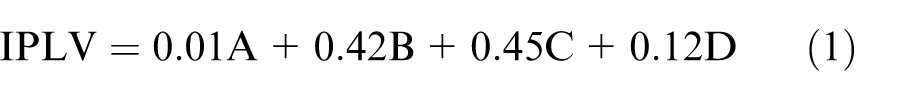
where A is the coefficient of performance (COP) at 100% load, B is the COP at 75% load, C is the COP at 50% load, and D is the COP at 25% load.
According to equation (1), the proportions of 75% and 50% loads are much higher than full load or 25% load. The proportion of the full load is very small; the compressor design which is focused on full load should be significantly changed.
Under part-load condition, actuating the inlet guide vane (IGV) can improve the efficiency of part load, postpone the occurrence of surge, and improve IPLV. However, when the flow rate decreases continuously, even though IGV is further turned off, the efficiency of part load cannot be improved and the surge flow rate cannot be decreased. The cause is not the impeller, but the diffuser. The inlet blade angle of the vaned diffuser matches the design flow rate; therefore, there is an incidence loss at a low flow rate. The incidence loss increases rapidly as the flow rate decreases continuously. If there is no three-dimensional (3D) stall, friction loss will dominate the performance of vaneless diffuser (VLS), and pressure loss will not increase rapidly as the flow rate decreases. However, if 3D stall happened in a VLS, the pressure loss will increase sharply, and surge is unavoidable.
Pinarbasi and Johnson 2 used a hot-wire anemometer to measure the 3D velocity and six Reynolds stresses in various flow rates of a VLS of a backswept compressor. Goto 3 used numerical calculation to discuss the flow fields of an impeller with a vaned diffuser in off-design conditions of a low-specific-speed centrifugal pump. Tamaki et al. 4 experimentally discussed the centrifugal compressor in a marine turbocharger with vaneless and variable vaned diffusers. The results showed that the efficiency was degraded by reducing the throat area of vaned diffuser but the surge was postponed. Salvage 5 indicated that increasing the distance between an impeller and a vaned diffuser contributed to reducing the sound pressure, but worsened the surge-line under part load. Koumoutsos et al. 6 used computational fluid dynamics (CFD) to simulate unsteady behavior between an impeller and a diffuser with equal or multiple blades. Ribi and Dalbert 7 used a one-dimensional model to estimate the performance of a diffuser. The empirical correlation was corrected by the existing diffuser. Sun and Tsukamoto 8 used CFD to estimate the performance of the design and off-design conditions of a centrifugal pump with a diffuser. Wang and Tsukamoto 9 used a two-dimensional vortex method to calculate the unsteady-state flow under off-design conditions. Yaras and Orsi 10 measured the unstable inflow effect of a fishtail diffuser in design and off-design conditions. Zhu and Kamemoto 11 used the advanced Lagrangian vortex-boundary-element method to simulate the interaction between an impeller and a guide vane in design and off-design conditions. Zhang et al. 12 used digital particle image velocimetry (DPIV) to measure the flow angle at the impeller exit and in the VLS. Benini et al. 13 used experimentation and numerical calculation to enhance the performance of the vaned diffuser. Kim et al. 14 discussed the effect of changing the vaned diffuser geometry on the compressor performance. Pavesi et al. 15 experimentally discussed the instability of pressure and flow in design and off-design conditions of a centrifugal pump with a vaned diffuser. Zhang et al. 16 used an artificial neural network and genetic algorithm to improve the performance of a vaned diffuser. Anish and Sitaram 17 conducted a computational study to analyze various levels of impeller–diffuser interactions at four flow coefficients. Gaetani et al. 18 presented the results of a wide experimental campaign devoted to the understanding of the impeller–diffuser interaction. Jyothishkumar et al. 19 used the large eddy simulation to investigate the flow characteristics inside a centrifugal compressor at design and near-surge conditions. Jaatinen-Värri et al. 20 experimentally investigated the performances of three centrifugal compressor VLS near stall and choke conditions. Rao et al. 21 numerically explored the performance of a centrifugal compressor with four types of low-solidity diffuser at five flow coefficients.
In this study, a 550-RT (refrigeration ton) two-stage centrifugal chiller is analyzed. The first compression stage has a vaneless diffuser (VLS) and a low-solidity vaned diffuser (LSD), while the second compression stage has only a VLS. The geometries of LSD and VLS are varied to promote the part-load performance and lower the surge flow rate.
Physical model
In this study, a 550-RT chiller with two-shaft, two-stage centrifugal compressor is analyzed. This two-shaft compressor has two volute casings, and there is no de-swirled vane. The refrigerant flows out from the first stage through the intercooler into the second stage. Except that pressure and flow rate are related between the two stages, it is assumed that the flow field at the outlet of the first stage does not influence the second stage. The components of the first stage comprise IGV, impeller, VLS, LSD, and volute casing. The components of the second stage comprise IGV, impeller, VLS, and volute casing. The main geometrical data of compressor are shown in Table 1. The impellers of the two stages have 11 and 15 blades, respectively. The LSD of the first stage has 12 vanes, as shown in Figure 1. The first stage has a higher pressure ratio than the second stage, thus, the tangential velocity at the impeller exit is also higher. For the case only with VLS, a very large diameter of VLS and volute casing is required for recovering sufficient dynamic pressure; therefore, the LSD is commonly used for diffusion in the first compression stage. The second compression stage has a lower pressure ratio, and VLS is used for diffusion since the tangential velocity at the impeller exit is relatively lower. As the flow field of the first stage does not influence the second stage, the two stages are calculated separately. In addition, because the volute casing is in the downstream of the diffuser, it has slight effect on surge. If the volute casing is calculated simultaneously, the full impeller and full guide vane models are required, which needs huge computing resources. Therefore, the volute casing is excluded in the computation.
Main geometry data of two-stage compressor.

LSD: low-solidity vaned diffuser; VLS: vaneless diffuser.

The present 550-RT two-shaft, two-stage centrifugal compressor: (a) schematic diagram, (b) the first-stage impeller and diffuser, and (c) the second-stage impeller.
The first stage can rotate LSD (as shown in Figure 2(a)) or can reduce the width of the diffuser (as shown in Figure 2(b)) in response to the low flow rate. The second stage uses VLS for diffusion, rather than LSD. The VLS is adjusted by reducing the outlet width to reduce the flow area, which is shown in Figure 2(c).

Variations of diffusers: (a) rotation of LSD, (b) first-stage width reduction, and (c) second-stage width reduction.
The assumptions of this study are described below.
The compressor rotates at constant speed, and the flow is regarded as steady state.
Solid wall is smooth surface.
Internal leakage and external leakage are ignored.
The working fluid used in this study is R-134a refrigerant, and the flow field is calculated by compressible governing equations, including continuity equation, energy equation, momentum equation, and refrigerant property chart. In this study, the rotational speed of the compressor is 11,000 r/min. The boundary conditions are set as follows:
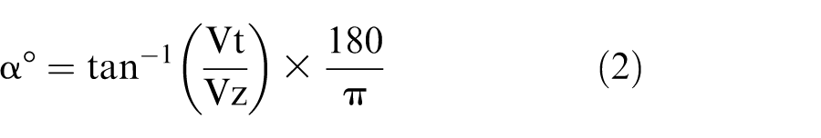
The front end of inlet extension is set as a pressure boundary. The inlet total pressure of the first stage is set as 357,000 Pa, and the second stage is set as 570,000 Pa. The inlet temperatures of the first and second stages are set as 6°C and 24.5°C, respectively. IGV model is not built in this study, but sets the tangential velocity/axial velocity (Vt/Vz) value, which controls the angle, α°, of the fluid flowing into the impeller. α° is defined as follows
The rear end of outlet extension is set as a static pressure boundary, and the outlet pressure is adjusted to calculate the mass flow rate, thus forming a P–Q curve.
Experimental measurement and solution methodology
This study uses the CFD package of Concept NREC to calculate the flow field and performance of the compressor. The multi-block solver is used with three-order upwind discretization. The governing equations used in this solver are the Reynolds-averaged full Navier–Stokes and low Mach number pre-conditioning equations, and the Spalart–Allmaras turbulence equation. The convergent criteria are that the residuals of velocities, pressure, and turbulence kinetic energy are all smaller than 10−4. The mesh of the passage between blades is shown in Figure 3, and there are dense grids nearby the solid wall.

Grid distribution.
The grid independence test is performed and the flow rate is compared in this study. The cell numbers are 183372, 364266, 726604, and 1066056, as shown in Table 2. According to Table 2, this study selects 726604 cells.
Grid independence test (the first stage, pressure ratio: 1.675).

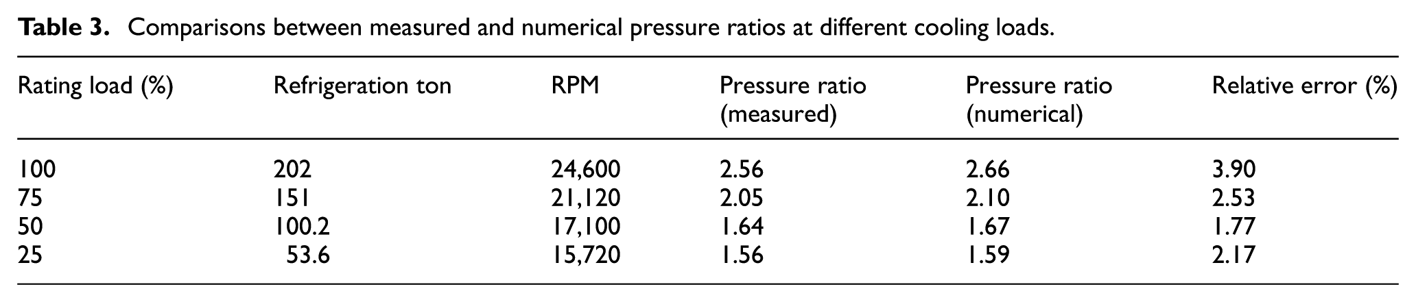
This study uses an induction motor (IM)-driven single-stage 200-RT chiller with magnetic bearing and VLS to compare numerical calculation with the experimental measurement. The results are shown in Table 3. The performance of the chiller is measured according to AHRI (Air Conditioning, Heating, and Refrigeration Institute) standard 551/591 (SI). The measurement error of chiller capacity is about 2%, and the error of the manometer is about 0.5%. The rotational speed is obtained by the detector of the magnetic bearing, and the error is about 0.3%. The refrigerant mass flow rate of different loads is calculated by heat balance between the refrigerant-side and water-side heat transfer. Table 3 shows that the average relative error of four loads is about 2.6%, thus, they are fairly consistent and prove that the numerical calculation is reliable.
Comparisons between measured and numerical pressure ratios at different cooling loads.
Results and discussions
The “surge flow rate” in this study means the refrigerant flow rate in which surge occurs at specific rotational speed. It is difficult to determine the surge flow rate even in an experiment, as the pressure is quite unstable when the surge occurs and the flow rate varies drastically, thus, data acquisition is difficult. When more than two fluid components stall, the flow separation zones are possibly connected in series forming a large recirculating flow, thus, the flow field is very disordered. This is one of the criteria for judging surge in some commercial software. The flow separation can be viewed by CFD for the judgment of surge flow rate. However, analysis is difficult when a surge occurs. As flow with large recirculation, the numerical computation is difficult to converge. Therefore, CFD calculations start from low outlet pressure and calculate the associate flow rate; as it converges, the outlet pressure is increased and the associate flow rate is calculated. This process goes until convergence fails due to too large recirculating flow. In this article, the minimum convergent flow rate is called the “surge flow rate”; however, this surge flow rate may not be the actual flow rate when the surge occurs.
In this study, the effect of IGV is regarded as preswirl at the blade inlet. Therefore, stage efficiency in this study does not consider the efficiency loss caused by IGV. The preswirl angle α° which is defined in equation (2) means the absolute flow angle at the impeller inlet is α°, where larger α represents larger preswirl. The LSD β° angle means the LSD rotates β° anticlockwise (as shown in Figure 2(a)), as based on the original design (70° between vane inlet and radial direction). The following results are free of volute casing.
First-stage, fixed LSD width, rotatable LSD
Figure 4 shows the static pressure ratio, PRs, and stage efficiency η at different LSD rotation angles without preswirl. Without preswirl means the IGV is fully opened (0°). The refrigerant flow rate at different loads divided by the flow rate at full load is defined as the “flow rate ratio.” It is observed that the static pressure ratio decreases as the flow rate ratio increases at the same LSD rotation angle. When the LSD rotation angle increases, the choke flow rate and the surge flow rate decrease.
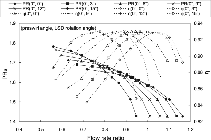
Stage pressure ratio and stage efficiency at different LSD rotation angles without preswirl.
Figure 5 shows the flow field at the condition with no preswirl, LSD of 15°, and flow rate ratio of 0.8. A small recirculating flow occurs at impeller exit near shroud. The recirculating flow in this study is caused by flow separation or stall, and it does not appear at design flow rate. When the flow rate ratio decreases to 0.56, this recirculating flow becomes very large, and the computation lower than this flow rate cannot converge. Adjusting the LSD angle when there is no preswirl is effective to some extent. The decrease in surge flow rate becomes more and more indistinct as the LSD rotation angle increases. In this study, the maximum LSD rotation angle is limited to 15°, because the inlet angle of LSD at full-load flow is only 20° (included angle to tangential direction). According to the efficiency curve in Figure 4, the maximum efficiency point moves toward lower flow rate ratio as the LSD rotation angle increases. The maximum efficiency values at different LSD rotation angles are almost the same.
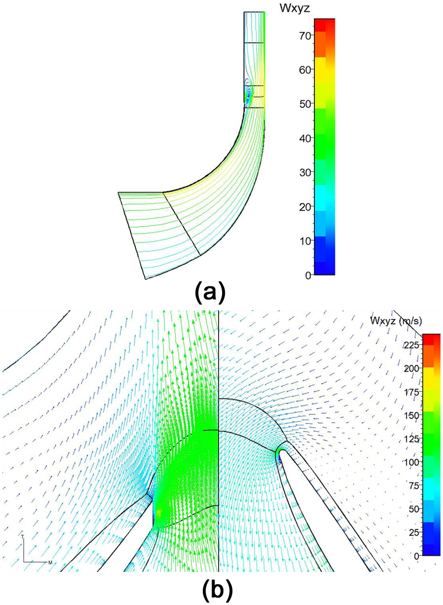
Flow field of no preswirl, LSD of 15°, and flow rate ratio of 0.8: (a) flow field of meridional mean plane and (b) r-θ plane flow field close to shroud (left: relative velocity; right: absolute velocity).
Figure 6 shows the total pressure ratio, PRt, and the efficiency of the first-stage impeller at different LSD rotation angles without preswirl. In the case of constant rotational speed without preswirl, the rotor efficiency is slightly influenced by LSD rotation when the flow rate is high. When the LSD angle is less than 9° and the flow rate ratio is higher than 1.1, the efficiencies are about the same. Because there is no recirculating flow at the impeller exit when the flow rate is high, the downstream component, LSD, has little effect on impeller. However, the influence becomes significant when the flow rate is low. Figure 7 shows the flow field of no preswirl, LSD of 0°, and flow rate ratio of 1.1. It is observed that there is no flow separation between LSD and impeller nearby the shroud. Hence, the change of LSD angle has little effect on the impeller. When the flow rate is low, flow separation may occur at the impeller exit just like Figure 5, and the fluid flows back into the impeller, thus, the flow field of LSD influences the exit pressure of the impeller. According to Figure 6, the LSD angle increased at low flow rate ratios which results in the reduction of incidence angle; therefore, the recirculating flow is small and less influent on the impeller. When the flow rate is low, the upstream flow field is easy to be influenced by downstream flow.

Impeller performances at different LSD rotation angles without preswirl.

Flow field of no preswirl, LSD of 0°, and flow rate ratio of 1.1: (a) flow field of meridian mean plane and (b) flow field of r-θ plane close to shroud.
It is known that preswirl can reduce surge flow rate. The primary function of preswirl is to change the flow angle and relative velocity at the impeller inlet, which inhibits the flow separation in the impeller. Besides, the density at the impeller exit reduces, and the meridional velocity at the impeller exit increases. Thus, the absolute flow angle at the inlet of LSD decreases which is benefic to improve the performance of the diffuser at low flow rate.
Figure 8 shows the results of preswirl 20°, 30°, and 40°. In different preswirls, the curve becomes steeper as the LSD angle is adjusted. The pressure ratio at a low flow rate increases with the rotation angle of LSD. As mentioned above, the minimum flow rate ratio of LSD 15° without preswirl is about 0.56. The flow rate ratio reduces to 0.55 in the case of preswirl 20° and LSD 6°. In the case of preswirl 30°, the flow rate ratio reduces to 0.54 when the LSD rotates at 3°. In the case of preswirl 30°, the surge flow rate ratio of LSD 12° decreases to 0.48. However, the surge flow rate of preswirl 20° and LSD 12° is similar to that of preswirl 30° and LSD 12°. At preswirl 40°, the surge flow rates of LSD 12° and 15° are almost the same. At the flow rate ratio of 0.5, preswirl 40°, and LSD 15°, a large recirculating flow occurs between the impeller and the LSD, and because it has extended into LSD, the computational result at further lower flow rate cannot be obtained. The problem is not at the impeller, but at the LSD. Therefore, increasing preswirl is not helpful. Since the rotation of LSD is limited, the surge flow rate cannot be further reduced.

Stage static pressure ratios at different LSD rotation angles in different preswirls: preswirl angles (a) 20°, (b) 30°, and (c) 40°.
Second-stage, variable width of VLS
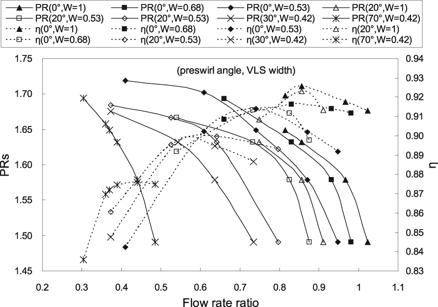
Figure 9 shows the static pressure ratios and efficiencies of different VLS widths without preswirl in the second stage, where W is the width ratio, which is resulted from dividing the adjusted width by the original width (the impeller exit width). According to Figure 9, the surge flow rate decreases obviously with the VLS width. It is observed that the surge flow rate ratio decreases from 0.81 to 0.41 when W decreases from 1 to 0.53. The adjustment of VLS width has obvious effect on reducing surge flow rate. Therefore, the primary cause of surge is VLS. Figure 10 also shows that the obtainable maximum efficiency decreases obviously with the VLS width. Although reducing the VLS width can enlarge the operation range of compressor, the efficiencies at low flow rates decrease.

Pressure ratios and efficiency in different preswirls and different VLS widths.
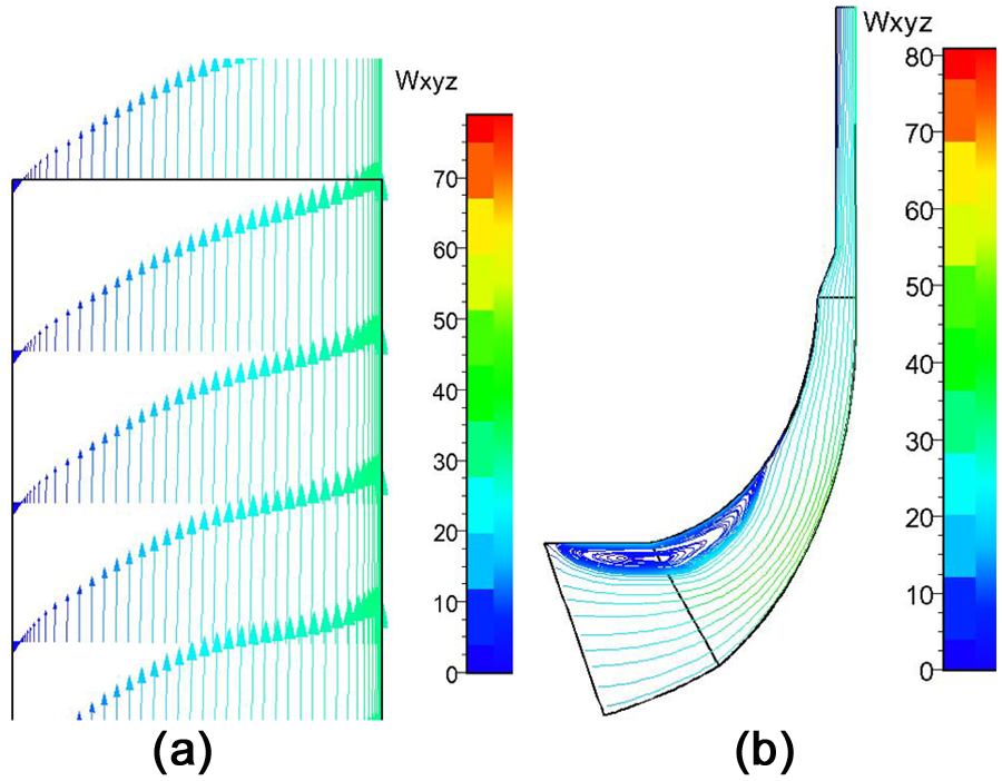
Meridional flow field of VLS at different flow rates without preswirl: (a) W = 1, flow rate ratio = 0.81 and (b) W = 0.53, flow rate ratio = 0.41.
When the flow rate ratio is 0.81 (as shown in Figure 10(a)), there is a reverse flow nearby the shroud which distributes almost throughout VLS. Under the condition with W = 0.53 and the flow rate ratio = 0.41 (as shown in Figure 10(b)), it shows that a recirculating flow occurs at the impeller inlet on the mean meridional plane. The recirculating flow usually expands from the suction side when the flow rate is low. The recirculating flow on the mean plane means the recirculation zone is quite large. The recirculation zone even expands to the leading end of inlet extension; therefore, a further lower flow rate cannot be calculated. This surge flow rate ratio is much lower than cases with large VLS width. This result implies that surge flow rate is effectively reduced when the VLS width is reduced. However, when the flow rate decreases to a certain level, continuously reducing VLS is ineffective, as large recirculating flow occurs at the impeller inlet, which becomes the first cause of surge.
Figure 9 also shows the static pressure ratio in different VLS widths at preswirl angle 20°. With preswirl, the narrower the VLS, the lower the surge flow rate. The minimum surge flow rate ratio is about 0.38. Adjusting preswirl angle and VLS width simultaneously has some effects on reducing surge flow rate. Since the recirculation zone in Figure 10(b) will become small if preswirl is active, the surge flow rate ratio can be further reduced. There is slight difference in maximum pressure ratio between the two cases: preswirl 20° with W = 0.53 and preswirl 30° with W = 0.42; their surge flow rate ratios are about the same (as shown in Figure 9). A large recirculating flow similar to Figure 10(b) appears in the impeller rather than in VLS when the preswirl angle is 30°, W is 0.42, and flow rate ratio is 0.38; thus, the cause of surge is not the VLS, but the impeller. Therefore, it is insufficient to reduce the recirculation zone while preswirl angle changes from 20° to 30°. The recirculating flow becomes small when the preswirl angle is 70° and the flow rate ratio is 0.38. However, it grows up when the flow rate ratio decreases to 0.3. It should be noted that there is no recirculation in the VLS as W = 0.42. Therefore, the cause of surge is recirculating flow in the impeller, the VLS is not stalled, and surge flow rate may be reduced again only by continuously increasing the preswirl angle.
According to Figures 4, 8, and 9, the effect of rotating LSD to reduce the surge flow rate is not as good as the effect of reducing VLS width. However, these figures also show that the efficiencies of rotating LSD are much better than reducing VLS width at low flow rate.
First-stage, stationary LSD, variable LSD width
Because the minimum flow rate ratio of the first stage is only 0.48, this study attempts to reduce LSD width in the first stage in order to reduce the influence of recirculating flow at low flow rates. In this part, the LSD angle is fixed. Figure 11 shows the static pressure ratio and efficiencies of no preswirl and different LSD widths, where W is the LSD width divided by the original width (impeller exit width). When W = 0.5, according to the figure, the surge flow rate decreases significantly, and the decreasing amplitude is better than the previous LSD 15°. Figure 11 also shows the stage efficiency of different LSD widths without preswirl. It is observed that the surge flow rate is reduced apparently when the LSD width is reduced; however, efficiency decreases accordingly.
Stage pressure ratios and efficiency of different preswirls and LSD widths.
Figure 11 shows the stage static pressure ratio of different preswirls when W = 0.5. The larger the preswirl, the lower the pressure ratio. However, the surge flow rate of preswirl 30° is slightly lower than that without preswirl. The surge flow rate ratio of preswirl 60° is about 0.1 lower than that of preswirl 30°. According to the aforesaid results, reducing the width of LSD is applicable to the first step of flow rate reduction, while preswirl is applicable to second step of flow rate reduction. In the first step flow rate reduction, the stall and recirculating flow mainly occur in the diffuser. The impeller in this study is strongly backward inclined, and such flow rate reduction is unlikely to cause big flow separation inside the impeller. Therefore, the impeller is free of large recirculating flow in the first step of flow rate reduction, and the preswirl has no obvious effect. However, when the flow rate decreases continuously, the recirculating flow in the impeller increases, and it must be inhibited by the preswirl. A small preswirl cannot effectively inhibit the recirculating flow, thus, only large preswirl is effective.
Figure 11 shows that the surge flow rate ratio is reduced slightly when the preswirl angle is 60° and when W decreases from 0.5 to 0.3. When W = 0.3, the friction loss resulted from a too narrow channel increases obviously. There is recirculating flow on the mean plane when the flow rate ratio decreases to 0.37, which means surge occurs due to the recirculating flow of the impeller. Thus, further reducing LSD width has no use in the reduction of surge flow rate, but results in large efficiency loss due to friction. It should be noted that decreasing the efficiency at low flow rate means reducing the performance of IPLV.
When W = 0.3, a higher preswirl angle is used and the flow field are calculated. The result shows that surge flow rate ratio of 0.36 can be obtained, and a calculation with a further lower flow rate ratio cannot have a convergent result. As the preswirl angle is larger than 70°, a large incidence angle causes a large incidence loss, which results in worse performance.
Conclusion
This study numerically investigates the effect of adjusting the preswirl angle, LSD rotation angle, VLS width, and LSD width of a centrifugal compressor regarding surge flow rate and low flow rate performance. The conclusions are described as follows:
Rotating LSD in the first stage can reduce the recirculating flow, increase the pressure ratio, and reduce the surge flow rate. There are slight differences in the maximum efficiency of different LSD rotation angles. The minimum surge flow rate is limited to 0.48 of full-load flow rate. The limitation is caused by LSD.
Reducing the width of the VLS in the second compression stage can reduce stall, increase pressure ratio, and effectively reduce the surge flow rate. Reducing the VLS width while simultaneously providing preswirl can greatly reduce the surge flow rate. The minimum surge flow rate is limited to 30% of full-load flow rate, in which efficiency decreases accordingly. The limitation is caused by impeller.
The effect of fixing the LSD angle and changing the diffuser width of the first stage for reducing surge flow rate is better than rotating the LSD and fixing the width, and the minimum surge flow rate is limited to 35% of full-load flow rate. The limitation is caused by impeller. Although the minimum surge flow rate is obviously lower than LSD rotation, the efficiency is also obviously lower.
For low and unsteady thermal loading, it is suggested to individually modulate the diffusers first, and then the IGV is adjusted when the flow rate cannot decrease apparently.
Footnotes
Appendix 1
Academic Editor: Oronzio Manca
Declaration of conflicting interests
The author(s) declared no potential conflicts of interest with respect to the research, authorship, and/or publication of this article.
Funding
The author(s) received no financial support for the research, authorship, and/or publication of this article.