
Abstract
An analytical model of the lateral motion of the endless belt in a two-pulley belt system is proposed. This model can be used to forecast the transient and steady lateral motion of the belt when the tilted angle of the steering pulley is time-variant and it is valuable in the design and assessment of belt lateral position controllers. The responses of the belt to variations in the tilted angle of the steering pulley according to a piecewise step function are solved using the delay differential equation solver dde23 in MATLAB. The validity of the model is confirmed by experiments. The simulation and experimental results show that the belt tends to move to the side with a shorter center distance. In the steady phase of the step responses, the lateral belt velocities at different positions tend to be coincident with each other. A closed-form expression of the steady belt lateral velocity is derived. The expression shows the steady belt lateral velocity is proportional to the input tilted angle and the belt speed, and it increases with an increase in the center distance and the pre-load tension and a decrease in the radius of the pulleys and the belt bending stiffness.
Introduction
Flat belts have been widely used for hundreds of years in many industrial and home applications to transmit power or motion. The dynamic characters of the belt–pulley coupled system have been researched extensively. The focus of these studies is the transverse and longitudinal vibration of the belt–pulley system and its influences on power losses.1–4
Controlling the lateral position of the belt is an essential problem in the design of devices with flat belts because the lateral motion of a flat belt has critical impact on the operational safety and performance of the whole device. In engineering applications, most belt lateral position controllers are based on a proportional–integral–derivative (PID) control scheme and do not take advantage of any model-based knowledge. This is mainly because the mechanism of lateral motion of the endless belt is not understood clearly, and the accepted dynamic model for the lateral motion of the endless flat belt has insufficiencies.
Research on the lateral motion of an endless belt is sparse. However, the lateral motion of the web whose properties are similar to flat belts has been researched extensively since 1960s. The term “web” especially refers to the long, thin flexible materials moving from an unwinding roll to a rewinding roll, such as textile, paper, metal strip, and plastic tape. The most significant work was done by Shelton and Reid.5,6 They proposed a first-order and a second-order dynamic models for a single web span. In the first-order model, the web is modeled as a string, and in the second-order model, the web is modeled as Euler beam. Young et al.7,8 developed a model based on the second-order model to describe the interaction of two web spans when the friction between the web and a roller is small. A systemic review on earlier studies can be found in Young and Reid. 9
Sievers et al. 10 modeled the web as Timoshenko beam, and their model is more accurate for short spans. They also proved that it is acceptable to model the web in a quasi-static manner for most web processes in industry. Benson 11 derived the lateral dynamics of a warped web based on the Timoshenko beam model. Wang et al. 12 used the Timoshenko beam model considering the dynamical behaviors of the web to design a Smith predictive controller to improve lateral position control of the web in wallpaper making processes. Yerashunas et al. 13 introduced the material’s viscoelastic damping property into the Timoshenko beam model.
There are marked differences between endless flat belts and the web. First, the web moves unidirectionally when processing, and the lateral dynamics of the web in the down-stream spans do not influence the lateral dynamics of the web in the up-stream spans. However, endless flat belts introduce an internal mechanical feedback. 14 Second, the wrap angles of flat belts on pulleys are much larger than the wrap angles of the web on rollers. In most studies, the contact zones between the web and a roller was assumed to be a contact line. For flat belts, the widths of the contact zones need to be taken into account. Han et al. 15 proposed a string model for the lateral motion of an endless belt considering the above differences. Egger and Hoffmann 16 studied the lateral motion of the flat belt in a two-pulley belt system, in which the centerlines of two pulleys are skew lines.
To reveal the laws of the lateral motion of an endless belt, some researchers studied the lateral motion of an endless belt using the finite element method (FEM) and multi-body dynamics analysis method. Cheng et al.17,18 simulated the belt lateral motion caused by angular misalignment of rollers using the commercial FEM software MARC. Zhang 19 discussed the flat belt skew of two-pulley drives through FEM simulation and also derived theoretical solution of the skew. Yoon et al. 20 developed an efficient analytical method to simulate the belt’s lateral motion completely integrating large deformable FEMs and multi-body dynamics. Kobayashi and Toya 21 studied the factors influencing belt lateral motion through experiments and simulations using multi-body dynamics analysis commercial software LMS DADS.
Forecasting the transient lateral motion of the belt when the tilted angle of the steering pulley is time-variant is vital in the design and assessment of belt lateral position controllers. However, almost all the existing models and analytic procedures are only valid for the steady lateral motion of the belt, except Han et al., 15 in which the bending stiffness of the belt is neglected in the string model, and its applications are limited. The aim of this article is to propose an analytical model of the lateral motion of an endless belt in a two-pulley belt system. The bending stiffness of the belt is considered and the belt is modeled as an Euler beam. We restrict the studied system to working under light-load conditions. Although it is incapable of applying in the power transmission problems, it still covers vast applications such as printers, mail-sorting machines, and automated teller machine.
Modeling of the lateral motion of an endless belt induced by angular misalignment of pulleys
System descriptions
The studied belt system consists of a driving pulley, a steering pulley whose pivot is parallel to the

Scheme of the studied two-pulley belt system: (a) isometric view, (b) top view (the deformation of the belt is overstated), and (c) front view.
A spatially fixed curvilinear coordinate
The lateral displacement of the belt is defined as a function of the curvilinear coordinate
The belt can be classified into free spans (ab and cd) and wrapping segments (bc and da). When the load of the belt system is light, we can consider there is no slip between the belt and pulleys in the wrapping segments. Once the belt touches a pulley, the belt will adhere on the pulley until it leaves the pulley. The friction between the belt and the pulley is static friction.
The belt is modeled as Euler–Bernoulli beam, whose cross section is always perpendicular to its neutral surface. Here, we modeled the belt in a quasi-static manner because the low-order natural frequencies of the belt are very low and the high-frequency transient responses can decay rapidly. 10
Model of free spans
The quasi-static governing equation of the deflection of Euler–Bernoulli beam whose length is

where
The general solution of equation (1) is

in which
Descriptions of the basis functions used in equation (2).

Calculating the second-order derivative of equation (2) with respect to
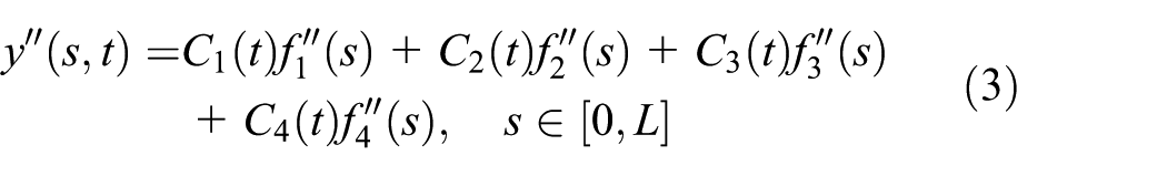
It can be seen that both
Model of wrapping segments
According to the assumption that there is no slip between the belt and pulleys, the lateral displacement of a point on the belt wrapping segments can be considered as the sum of two parts.
The first part is the lateral displacement of a point on the belt when this point comes to contact with pulleys.
The second part is the lateral displacement induced by the rigid motion of the pulleys. For the wrapping segment on the driving pulley, the second part has a value of zero because the axes of the driving pulley are always parallel with the
For the wrapping segment on the steering pulley, the lateral displacement induced by the rigid motion of the steering pulley is

where
In summary, for the wrapping segment bc

For the wrapping segment da
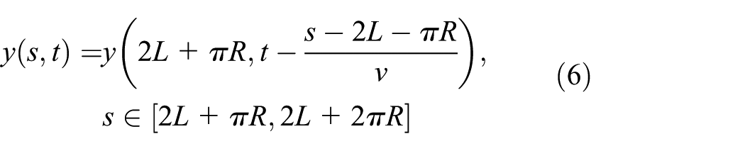
In Egger and Hoffmann, 16 Zhang, 19 and other previous studies, the delay terms were neglected and the tilted angle was assumed to be constant. They are able to forecast the lateral motion of the belt when the tilted angle is time-invariant. However, it is very important to model the lateral motion of belt under the time-variant tilted angle in the design and performance assessment of belt lateral position controllers. Using equations (5) and (6), we can overcome the limitation of previous studies, and it is able to forecast the belt lateral motion with time-variant tilted angle.
Boundary compatibility conditions at division points
Boundary compatibility conditions at division points from free spans to wrapping segments
In this section, the boundary compatibility conditions at the positions where the belt enter the contact zones on the pulleys are deduced. The deduction focuses on the division point b. The boundary compatibility conditions at the division point d can be derived similarly and the final results are listed directly.
Boundary compatibility conditions at the division point b
The velocity of a particle on the steering pulley at point b can be decomposed into components along the
Because of the convection of the belt speed

The velocity components along the

The condition that the velocity components along the

Substituting equation (7) into equation (8) yields

When the steering pulley rotates about the pivot, the contact line between the belt and the steering pulley will also rotate. Because the non-slip assumption is valid on the full width of the belt, the cross section of the belt should also rotate to follow the contact line. As shown in Figure 2, after a small period

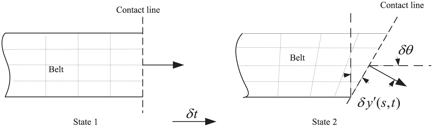
The geometric relation between the rotation angles of the belt cross section and the steering pulley.
Rearranging equation (9) and substituting it into equation (10) yields

Boundary compatibility conditions at the division point d
Similarly, the boundary compatibility conditions at the division point d are


Boundary compatibility conditions at division points from wrapping segments to free spans
Boundary compatibility conditions at the division point c
For the wrapping segments bc, according to equation (5), the derivation of

Thus, at the division point c, where

where
Owing to the memory function of the pulley, the second-order derivative of

The boundary compatibility conditions at the division point a
Similarly, at the division point a,

The second-order derivative of

Equations (15) through (18) all contain the delay terms.
Normalized model of the entire belt
A state vector

It is obvious that

According to equations (3), (9), (11), and (17)

According to equations (16) and (21)

According to equations (3), (12), (13), and (15)

According to equations (23) and (18)

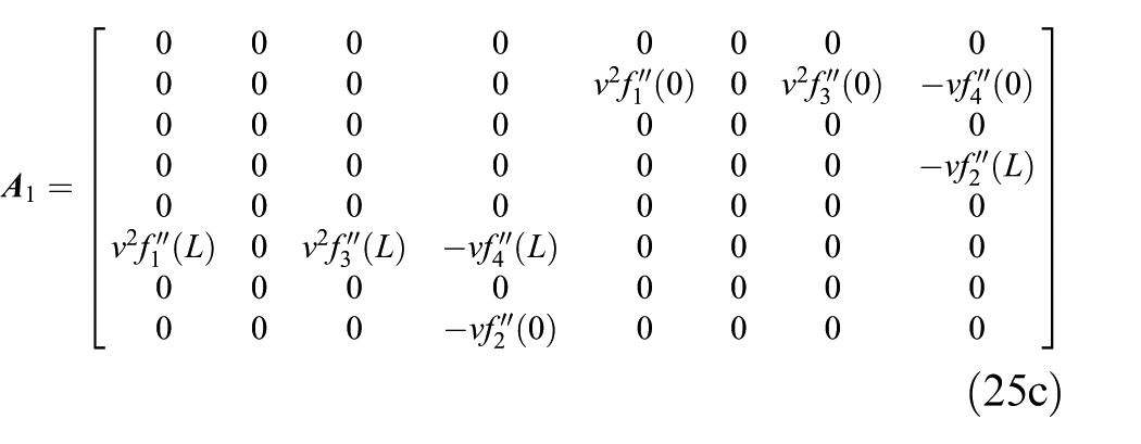
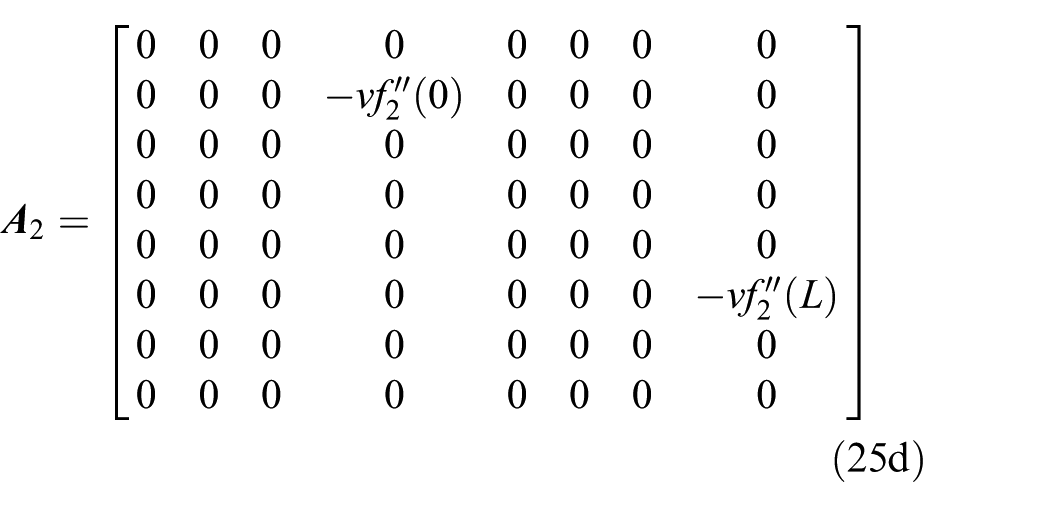
Based on equations (20) through (24), the normalized model of the entire belt can be obtained

where


After the state vector
Simulation and experiments
Equation (25a) is a linear inhomogeneous delay differential equation (DDE) with constant delays. After supplying sufficient initial conditions, it can be solved using the method of steps to obtain the exact analytic solutions. However, the analytic solutions may be quite complex, and it is very difficult to study long-term behaviors. In practice, the initial value problem of DDE is often solved numerically. In this work, the DDEs solver dde23 in MATLAB® (MathWorks, USA) is used to obtain the numerical solutions.
Simulation
In this section, an example is provided to demonstrate the solution described above. The lateral dynamic responses of the belt when the tilted angle of the steering pulley varies are obtained. The parameters of the studied system are specified in Table 2.
Parameters of the studied belt system.

The changes in input tilted angle of the steering pulley over time are shown in Figure 3.

Changes of the tilted angle of the steering pulley over time in the simulation.
The solution of an ordinary differential equation (ODE) is determined by its value at the initial point
For the DDE solver dde23, the error control property absolute error tolerance “AbsTol” and relative error tolerance “RelTol” are very important to guarantee the stability of solutions, and they should be chosen carefully. A series of trial simulations were done before this study. It was found that 1e−8 is the proper value of the error control property “AbsTol,” and 1e−4 is the proper value of the error control property “RelTol.” When “AbsTol” or “RelTol” is greater than the proper value mentioned above, the solution may become unstable. However, when using tighter tolerances, the computation time will be longer. The computation time under different tolerances is shown in Figure 4. The simulations were carried out on a LENOVO® M6600-N000 computer, whose CPU is INTEL® Core i5 6500@3.2 GHz and the RAM is 8 GB.

Computation time under different tolerances in dde23.
The lateral displacements of the belt at four positions are shown in Figure 5(a), and the lateral velocities of the belt at four positions are shown in Figure 5(b). Two overall trends can be observed in the simulation results:
Corresponding to the tilted angle input
When the tilted angle input

Simulation results of the studied belt system whose primary system parameters are specified in Table 2: (a) lateral displacements of the belt at four different positions and (b) lateral velocities of the belt at four different positions.
Focusing on the transient phase, one can conclude that the transient responses have the following characters:
When a step input is applied to the system, the belt at point b and point c, which are located at the entrance of the pulleys, respond immediately. Owing to the delays in the dynamic model, the belt at point c and point a, which are located at the exit of the pulleys, respond after a delay.
From Figure 5(b), it can be observed that the velocity of the belt at point b and point c, which are on the steering pulley, looks like a typical step response with overshoot; however, the velocities of the belt at point d and point a, which are on the driving pulley, have a reverse overshoot relative to the long-term steady response.
The characteristics of the transient responses of the belt can be concluded as follows. When the inputted tilted angles of the steering pulley are
Figure 6 shows the lateral displacement distributions along the entire belt at six different points in time. It can be observed that the shape of the belt curve changed little in the steady phase

Lateral displacement distributions along the entire belt at six different moments.
Specially, we examined the expansion of belt segment da on the driving pulley, as shown in Figure 7. In the theoretical analysis by Zhang,
19
it was assumed that in the stick area the belt is a straight line with a fixed incline angle on the expansion of pulleys. However, from Figure 7, it can be seen that the straight line assumption is true only in the steady phase
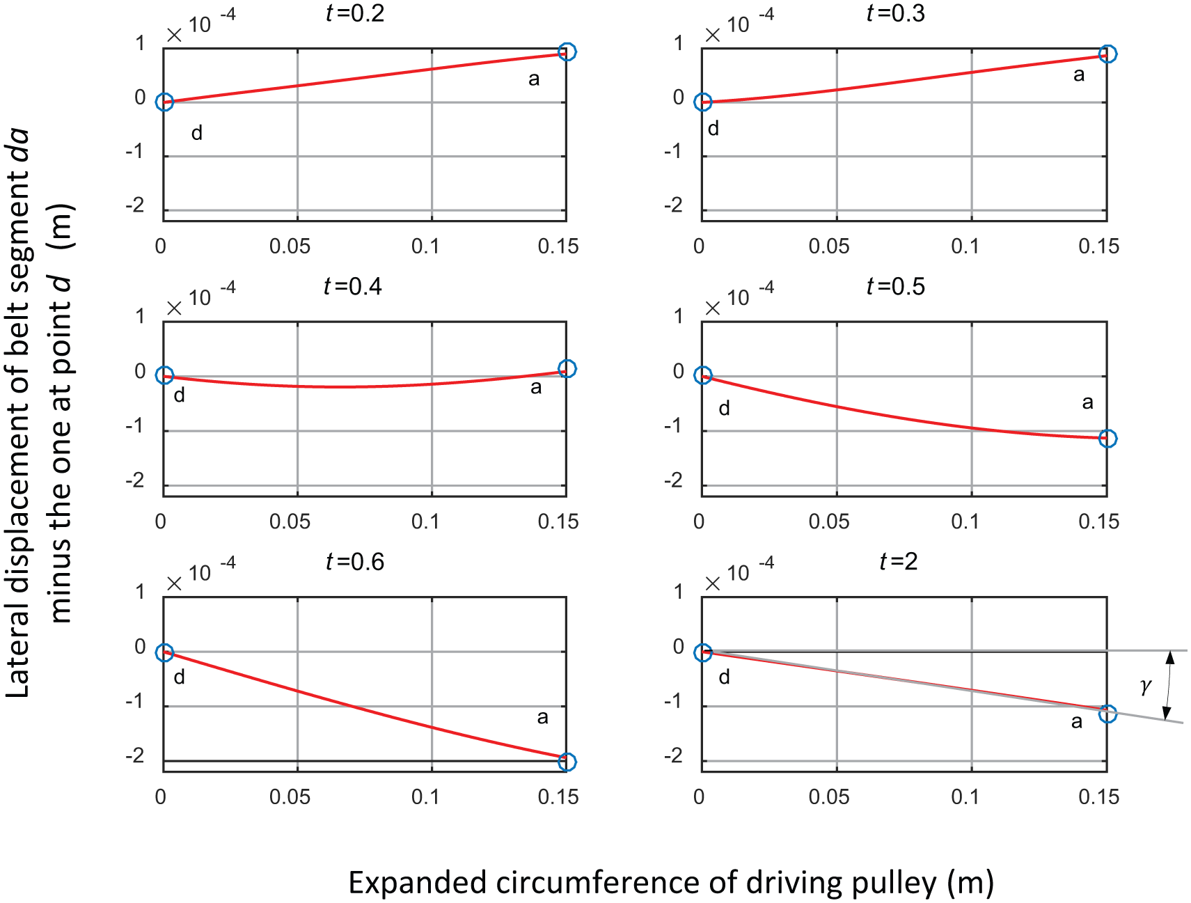
Expansion of belt on the driving pulley.
Denote the incline angle of the belt on the expansion of the driving pulley in the steady phase as
Experimental verification
To test the aforementioned model, an experimental verification was carried out using the test rig shown in Figure 8. The driving pulley was driven by a DC motor. The bearing blocks of the steering pulley can move along two guides to adjust the tension of the belt and the tilted angle of the steering pulley. The tilted angle of the steering angle was measured using a dial gauge. The tension of the belt was measured using a tension meter.

The test rig used in the experiments.
A photoelectric encoder mounted on the driving pulley was used to measure the travel distance
The key system parameters are the same as the ones used in the simulation specified in Table 2 except the belt speed. Because the lateral displacement of the belt was recorded as the belt traveled a fixed interval, the belt speed was not controlled accurately in the experiments.
Figure 9 presents a comparison between the experimental and simulation results when the tilted angle of the steering pulley is set at

Comparison between the experimental and simulation results: (a) lateral displacement of the belt at point a when
Closed-form expression of the lateral velocity of the belt in the steady phase
Both the simulation and experimental results show that a short period after the input tilted angle of the steering changes, the lateral velocities of the belt at different positions gradually become the same, and the shape of the belt changes little.
In this section, a closed-form expression of the lateral velocity of the belt in the steady phase is derived. Here, we introduce some assumptions according to the simulation and experimental results:
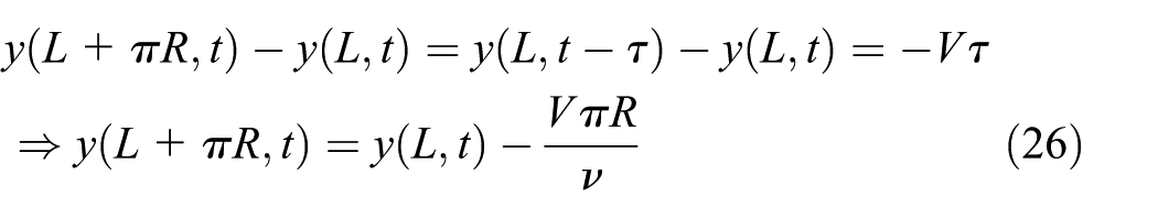
The steady lateral velocity of the belt
The shape of the belt do not change in the steady phase, and it determines the steady lateral velocity of the belt. Thus, we are only interested in the relative lateral displacement of the belt at different positions and are not interested in the absolute lateral displacement of the belt. Without loss of generality, we assume that
The tilted angle of the steering pulley
According to equation (5), it can be obtained
According to equation (6), it can be obtained

Equation (9) can be rewritten as

Equation (12) can be rewritten as

Equation (15) can be rewritten as
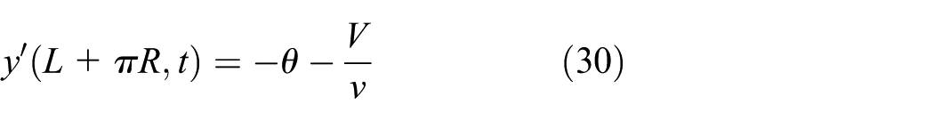
Equation (17) can be rewritten as

Under assumption 1, equation (11) yields

Under assumption 1, equation (13) yields

According to equation (3), substituting equation (26) through (31) into equations (32) and (33) yields an equation set

Equation (34) contains two unknown parameters:

Table 3 gives a comparison between the simulation results and the results calculated using closed-form expression (35). The data show that equation (35) is effective in the prediction of the lateral velocity of the belt in the steady phase.
Comparison between the steady lateral velocities computed using the numerical method and equation (35).
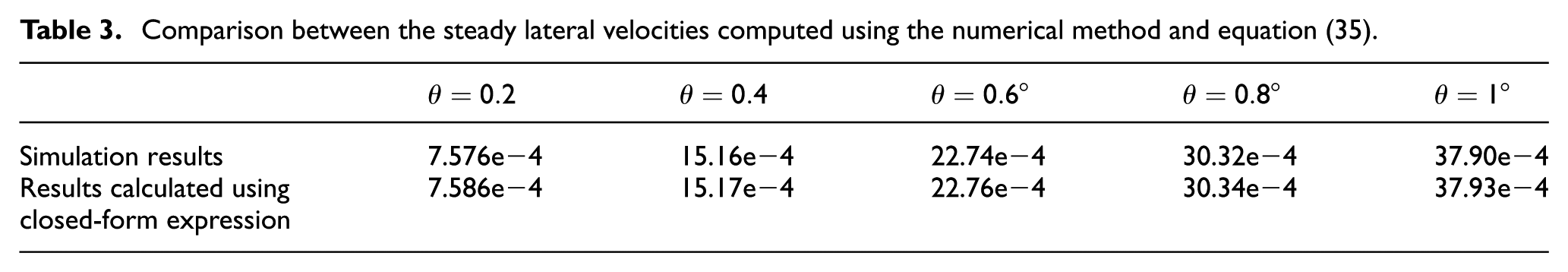
From equation (35), it can be directly seen that the steady lateral velocity of the belt
Figure 10 shows the variation in the steady lateral velocity of the belt with the center distance and the parameter
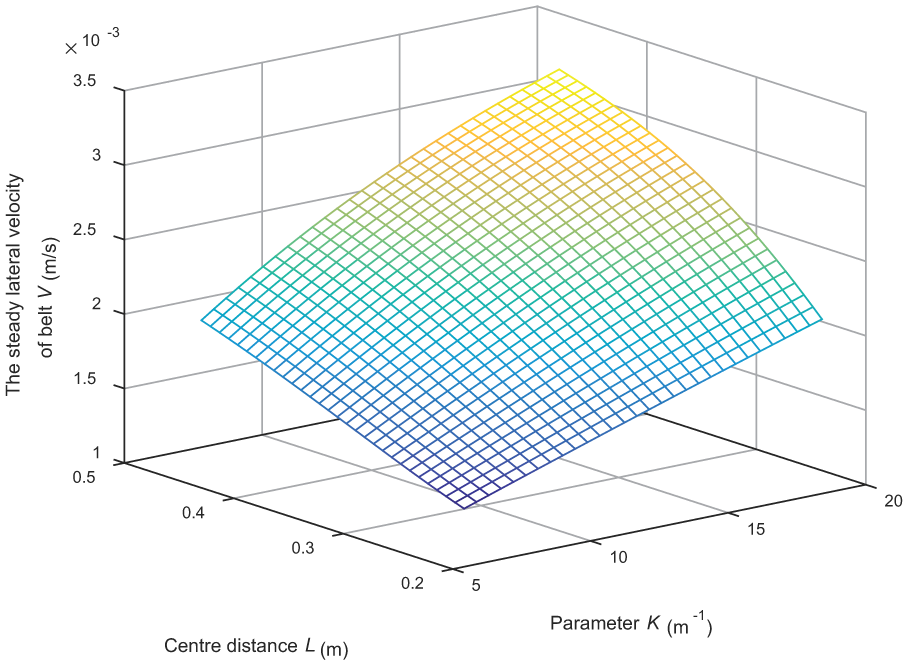
Variation in the steady lateral velocity of the belt with the center distance and the parameter
Conclusion
A model of the lateral motion of the belt in a two-pulley belt system is proposed. This model can be used to forecast both transient and steady responses and is valuable in the design and assessment of belt lateral position controllers. The step responses of the belt are studied through numerical simulation. The validity of the model is examined by experiments. The closed-form expression of the steady lateral velocity of the belt is derived under some reasonable assumptions. The main characteristics of the lateral motion of the belt in a two-pulley belt system are as follows:
The belt tends to move to side has a relative smaller center distance when the centerlines of the pulleys are not parallel.
The step responses of the lateral motion of the belt can be divided into a transient phase and a steady phase. In the transient phase, which lasts for a short period of time, the lateral velocities of the belt at different positions are different. In the steady phase, the lateral velocities of the belt at different positions tend to be coincident.
The steady lateral velocity of the belt is proportional to the input tilted angle of the steering pulley and the belt speed, and it increases with increases in the center distance and increases in the tension of the belt. The steady lateral velocity also increases with decreases in the radius of the pulleys and decreases in the bending stiffness of the belt.
Footnotes
Appendix 1
Academic Editor: Davood Younesian
Declaration of conflicting interests
The author(s) declared no potential conflicts of interest with respect to the research, authorship, and/or publication of this article.
Funding
The author(s) disclosed receipt of the following financial support for the research, authorship, and/or publication of this article: This work was supported by the National Natural Science Foundation of China (Grant No. 51405518) and the Foundation of State Key Laboratory of High Performance Complex Manufacturing (Grant No. zzyjkt2014-04).