
Abstract
Up to present, there have been numerous articles on ellipse detection. However, it is still a great challenge especially for embedded application with restricted available computing and memory resources. To handle this problem, a novel and effective method is presented for ellipse detection. The method consists of two main steps: extraction of elliptic edge contours and edge contours grouping. These two steps are integrated to improve the accuracy and speed of the method. Finally, the aim of this method is to process high-resolution image for embedded system, which needs fast and accurate ellipse detection with limited computational and memory resources.
Keywords
Introduction
The ellipse detection is an important investigation area in pattern recognition and computer vision since elliptic objects are the commonest objects in real images. General consensus shows that approaches used now mainly fall into three categories: fitting-based method, voting-based method (Hough transform (HT)-based method), and contours following method.
As one of the earliest methods, fitting-based method is mostly based on least square.1–5 In least square–based method, first, edge points are put into the mathematical model of ellipse, and the ellipse fitting is transformed into elliptical parameter equations. Then, the solution is obtained by minimizing the residue in elliptical parameter equations. Evidently, fitting-based method is not suitable for using alone since each edge point used in this method is required to be on the boundary of same ellipse.
HT was proposed for the purpose of line detection at first 6 and was found applicable for ellipse detection, 7 which is well known as simplified Hough transform (SHT). However, practical application of SHT is difficult because of massive computation and large memory demand. To settle those problems, some prior researches were conducted based on modified HT mainly in two categories. One is to reduce the number of voting points8–11 such as randomized Hough transform (RHT)8,9 and probabilistic Hough transform (PHT). 10 Despite the fewer inputs, there still exist lots of problems in such method, such as invalid sampling and too much iteration, especially for noisy image. In the other category, the five-dimensional parameter space is divided into lower dimensional subspaces according to geometric property of ellipses.12–15 Unfortunately, they show obvious disadvantage that they are not appropriate for small-scale ellipses due to large error.
In contrast to HT-based methods, which focus on global contours, the following method pays attention to local contours. Generally, it consists of two steps: the first is to connect the adjacent edge to form contours, and the second is to apply election strategies to group the contours that belong to same ellipse and to estimate elliptic parameters by fitting-based methods or HT-based methods. Contours following methods are advantageous over HT-based methods in terms of the amount of computations and execution time. Much research has been conducted recently based on contours following method. For the first step, arcs are obtained from segmentation16,17 or merging algorithm.18,19 For the second step, grouping of arcs are performed based on continuity,18,19 convexity,17,20 curvature,17,21 centers of ellipses,17,20,22 and ellipse fitting error. 21 However, some of them are constrained by various problems in real images. For instance, continuity is valid for grouping only if arcs on the same ellipse are not far from each other.
While most of the research devoted to ellipse detection focus on handling general cases of occlusion, overlapping, and noise and ignore embedded application. In one of our ongoing projects, a series of satellite mockups are required to estimate pose, for which real-time ellipse detection should be performed as the first step. On-orbit operation puts strict requirements on weight, power consumption, and volume of the hardware, and such requirements restrain the computational capability and memory resource of hardware. Moreover, the large-resolution image (2048 × 2048 pixels) needs to be processed. In summary, high computing speed and low-memory resource demand is required for ellipse detection algorithm under this circumstance.
This article focuses on embedded application. Figure 1 shows the overview of the proposed approach. For the first step, extraction of elliptic edge contours is performed in three major blocks: edge point detection and thinning, edge contour detection, and segmentation and merging. Smooth edge contours without any branches are obtained from this step. For the second step, edge contours that satisfy three conditions are grouped. Consequently, detected ellipses, represented by groups of edge contours, are obtained.
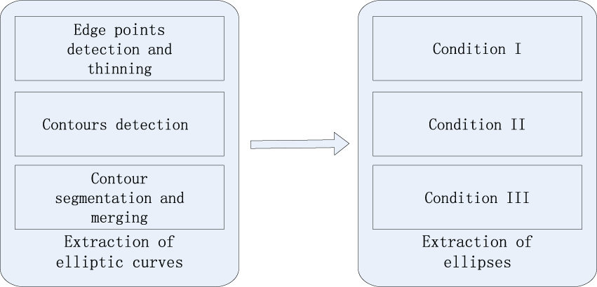
Flowchart of the proposed algorithm.
An example of hardware structure for our ongoing project is shown in Figure 2. Since the edge point detection and thinning process are for the whole image, which leads to mass calculation, they are implemented quickly in field-programmable gate array (FPGA) through pipeline operation, while other algorithms are running in digital signal processor (DSP) for its excellent floating-point arithmetic.

Block diagram of the hardware structure.
Extraction of elliptic edge contours
This section presents the extraction of smooth edge contours without any branches. First of all, edge points are extracted from the input image, and thinning algorithm is used to obtain one-pixel-wide edge as mentioned in MATLAB. Then, a novel algorithm is proposed to connect adjacent edge points and form edge contours. Finally, a fast image segmentation and merging method is performed on contours to obtain smooth edge contours.
Edge point detection
Sobel operator is used to detect edge points. We defined every detected edge points as

Algorithm implementation in FPGA.
Edge thinning
In this subsection, one-pixel-wide edge image is obtained to improve extraction accuracy. Given an edge point

where

Encode table (left) and eight neighborhoods (right).
Edge contour detection
After obtaining single-pixel edge, a novel algorithm is employed to connect adjacent edge points and form edge contours without any branches. First, a new contour begins with an edge point that is defined as end point. Second, the position of next point on the contour can be calculated with the encoding value of current point. Finally, the type of the new point is detected. If it is the point defined as process point, then the second step and the last step are repeated. Otherwise, detection of this contour is completed. The key points are described as follows:
The edge points in
Suppose an end point

Contrarily, we define the direction from
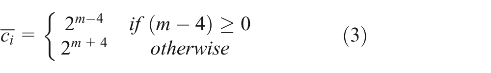
In most instances except for cases mentioned in key point 4, equation (2) and (3) can be combined into equation (4) to calculate

Then, the position of

In particular,
3. If a process point

An example is shown in Figure 5 where point 2 and point 3 are process point. First, the starting point of a contour is the end point 1 with its corresponding encoding value
4. If a branch point

Illustration of process point updating: (a) calculate position of point 2, (b) update the encoding value of point 2 and calculate position of point 3, and (c) update the encoding value of point 3 and calculate position of point 4.
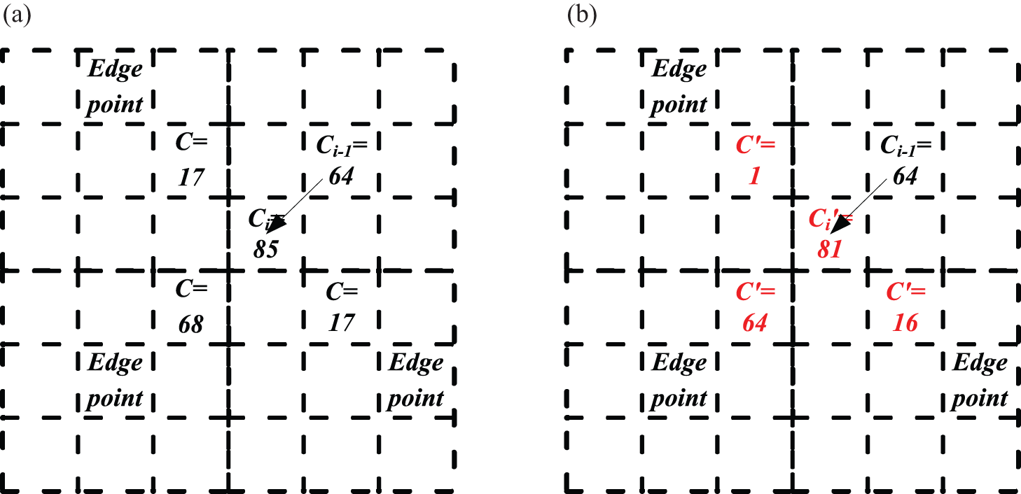
Illustration of branch point updating: (a) the detected branch point i and (b) update the encoding value and their types of all eight-connectivity edge points.
Algorithm 1
Update the encoding value of all eight-connectivity edge points of branch point
update adjacent edge points in
Keep in mind that the proposed contour detection method is especially suitable for application in embedded system since it is faster and requires lower memory resource than other methods by calculating the position of the next point on the edge contours instead of searching for its eight-connectivity points. We present the detailed analysis in section “Discussion and comparison.”
Criteria are proposed below to exclude edge contours that are not salient enough:
Exclusion criteria 1 (E1): number of points supporting the edge contour is greater than a given threshold
Exclusion criteria 2 (E2): distance between lines (formed by joining the end points of the edge contour), and the middle point is larger than a given threshold
A set of edge contours
Contour segmentation and merging
Segmentation
Since elliptic edge contours should be smooth and contain no inflexion point, contour segmentation will be performed on edge contours at split points. Ideally, smooth edge contour means that the change of curvature between two adjacent points is almost constant. Given an edge contour as the collection of points
where
Finally, every local maximum value in

where

Illustration of segmentation and merging: (a) split points (red plus) by segmentation, (b) edge contours obtained by segmentation, and (c) new edge contour by merging.
Merging
Due to image noise or overlapping, some of the segments of an edge contour may belong to same ellipse. This may lead to additional calculations in the step of grouping. Consequently, an effective merging method is presented to improve calculation speed. Let
Extraction of ellipse (edge contours grouping)
After smooth edge contours detection, edge contours, which belong to same ellipse, are grouped together.
Pair grouping strategy
Given two edge contours

Pair grouping strategy.
Pair selection method
Condition I is inspired by the fact that “relative” gradient direction is same everywhere on the edge of an ellipse (from inside/outside to outside/inside). Given
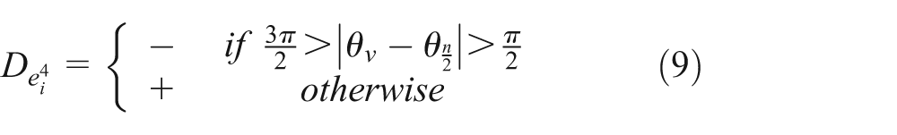
As shown in equation (9), negative value represents the edge contour gradient direction from outside to inside, while positive value represents the opposite direction. Figure 9 shows two ellipses in different “Relative” gradient direction. The value of

“Relative” gradient direction.
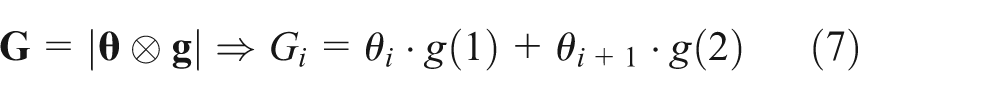
Condition II contains requirements for both the shape and location of the edge contours that belong to same ellipse. Let the function of

If

where

Condition III (necessary and sufficient conditions) is a fitting error measures. An ellipse is fit to all the supporters of two edge contours in a pair by mean square error minimization. The fitting error is defined by a ratio as follows

where N is the number of supporters supporting two arcs in pair and n is the number of supporters not only supporting two arcs in pair but also supporting the fitting ellipse. Obviously, there exists a high possibility that two edge contours belong to same ellipse if err is small. So, the condition III can be expressed as

where
Procedure of grouping
In section “Pair grouping strategy,” the pair grouping strategy defines three important conditions. We define detected ellipses as a set of edge contours
Algorithm 2
Group edge contours that belong to an ellipse among
enter
enter
enter
Finally, parameters of detected ellipses can be calculated based on least squares fitting technique for each
Discussion and comparison
A detailed analysis is conducted for major steps of the proposed ellipse detection theoretically by comparing them with other literature. And an example of real image (comes from our experiment) as well as all steps of detection ellipse is shown in Figure 10.
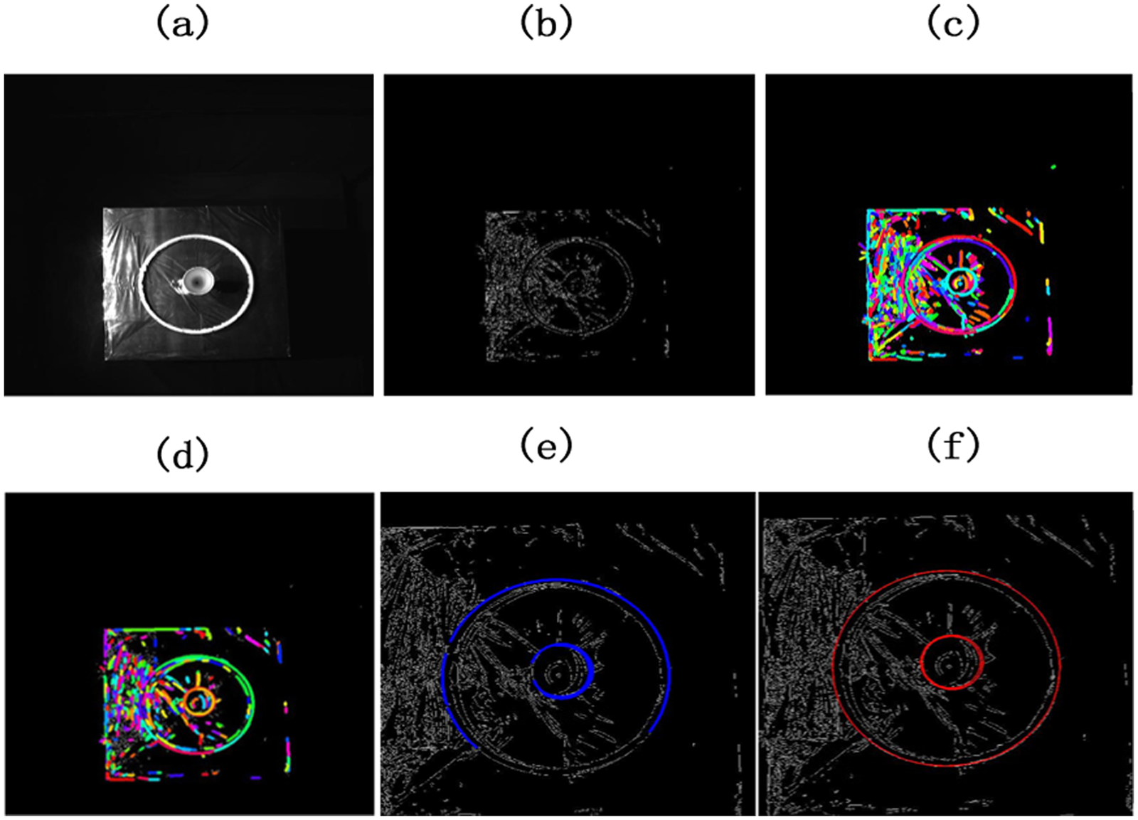
Illustration of ellipse detection process: (a) test image (2048 × 2048 pixels), (b) edge image, (c) edge contours, (d) segmentation and merging effect, (e) grouping effect, and (f) fitting ellipses.
Edge contours detection
The position of each point on a contour is calculated based on encoding value as specified in section “Edge contours detection,” while other approaches search edge points around the last point.16–18,20 However, search algorithm is very time-consuming because it searches from the whole set of edge points. Some approaches create a sparse matrix to mark edge points to improve the calculation speed according to Kovesi’s code. 24 On one hand, the proposed method requires lower memory resource, which allows to achieve calculation in limited-performance embedded system especially handling high-resolution images. On the other hand, the proposed method is performed faster than search algorithm in embedded system because the sparse matrix must be stored in external storage (static random-access memory (SRAM)). Table 1 shows the running time in embedded system as illustrated in Figure 2. The result shows that the proposed algorithm outperforms the most commonly used algorithm in terms of both time complexity and space complexity for the embedded system.
Time complexity of edge contour detection.

SRAM: static random-access memory.
Contour segmentation and merging
Contours segmentation is performed by calculating the change of gradient. Unlike the method of Prasad et al., 17 this method does not need to fit lines and is fast to calculate. A fast method, which avoids time-demanding segmentation, is proposed by Fornaciari et al. 20 However, Fornaciari et al. 20 forcibly split curves into shorter segments even if the curvature of contours changes continuously and smoothly, the procedure may generate many short contours which cause bigger calculation error of geometrical characteristics.
Pair grouping strategy
As described in section “Extraction of ellipse (edge contours grouping),” the two fast and effective necessary conditions (conditions I and II) are introduced before condition III. Condition I is based on “relative” gradient direction, while condition II indicates requirements for both shape and location. Many articles16,20,22 compute the convexity of edge contours for grouping, while the proposed method does not need to because it is implied in condition II. Our method is faster to compute and is more discriminative. For example, for 214 edge contours (refer to Figure 10), the theoretical execution time for checking is 22,791 (calculated by combination
Execution times of each condition in section “Extraction of ellipse (edge contours grouping).”

Discussion on control parameters
Five control parameters of the proposed method are discussed in this section. The control parameter
The control parameter
The control parameter
The control parameter
The control parameter
Experimental results
Various experiments are conducted to evaluate the proposed method for ellipse detection, and the results are compared with some recent researches proposed by Liu and Qiao, 22 Prasad et al., 17 and Fornaciari et al. 20 F-measure, 17 precision, and recall are used to evaluate the detection effectiveness; the larger, the better. One group of synthetic images and two groups of real images are considered in experiments in sections “Synthetic images” and “Real images,” respectively. All methods are implemented in C except Prasad et al. 17 and run in MATLAB on a personal computer (PC) installed with i7 system for simulation, without parallelization.
Synthetic images
The proposed method and compared methods are tested in various synthetic images which contain occluded or overlapping ellipse targets. First, m ellipses are generated in a synthetic image (300 × 300) by randomly selecting parameters of ellipse, then manual adjustments are performed if necessary to obtain occluded or overlapping ellipses. The value of semi-axis is limited in the range
Figures 11 and 12 show the performance of the proposed method and compared methods. The experiments on images show that the performance of Prasad et al. 17 method and the proposed method is the best. Liu and Qiao 22 method gives a poor performance especially in occluded ellipses for obvious limitations in edge contours extraction where it does not process the unsmoothed part of edge contours. Fornaciari et al. 20 method shows lack of capacity of detecting images with less edge pixels. Several examples of synthetic image detection are given in Figures 13 and 14.

Comparison of performance of different methods for synthetic images with occluded ellipses.

Comparison of performance of different methods for synthetic images with overlapping ellipses.
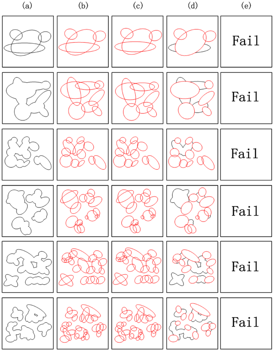
Examples of performance of different methods for synthetic images with occluded ellipses: (a) original ellipses, (b) our proposed method, (c) Prasad et al., (d) Fornaciari et al., and (e) Liu and Qiao.

Examples of performance of different methods for synthetic images with overlapping ellipses: (a) original ellipses, (b) our proposed method, (c) Prasad et al., (d) Fornaciari et al., and (e) Liu and Qiao.
Real images
The proposed method and the compared methods are evaluated on two different sets of real images. One set (called dataset I) is a portion of Caltech 256 database 25 with low-resolution images (about 300 × 200 pixels), the other set (called dataset II) is the set of images of satellite models taken in darkroom, with high-resolution images (2048 × 2048 pixels).
Dataset I
Images in dataset I (a total of 300 images) are randomly chosen from Caltech 256 with only one selection criteria that the image must contain at least one ellipse with adequate edge pixels (at least 20). The result of both effectiveness and execution time are shown in Table 3. Some results are depicted in Figure 15.
Performance on dataset I.

Examples of comparison of performance of mentioned methods in real images (dataset I): (a) original ellipses, (b) our proposed method, (c) Prasad et al., (d) Fornaciari et al., and (e) Liu and Qiao.
The proposed method gets better results than all other existing methods because of a good trade-off between execution time and detection effectiveness. Prasad et al. 17 method and the proposed method are the best of all methods in detection effectiveness, but Prasad et al. 17 method is quite slow for application of histogram count in its grouping step as shown in Table 1. Fornaciari et al. 20 method is the best of all methods in execution time. The proposed method is the second best in performance, very close to Fornaciari et al. 20 method in terms of execution time and the best in terms of detection effectiveness (same as Prasad et al. 17 method).
Dataset II
Since the proposed method aims at real-time detection for aerospace embedded application, numbers of experiments are conducted with different illuminations, distances, and angles to obtain images of satellite models in simulation of the space environment as shown in Figure 16 to form dataset II (a total of 400 images). Images from dataset II are with higher resolution (2048 × 2048) and more noisy than dataset I. All images are outputted, and the proposed method and other methods are evaluated off-line on the personal computer. Besides, the proposed method runs on embedded system where camera, DSP, and FPGA are integrated as shown in Figure 17.

Experimental environment: motive mechanism and the satellite mockup.
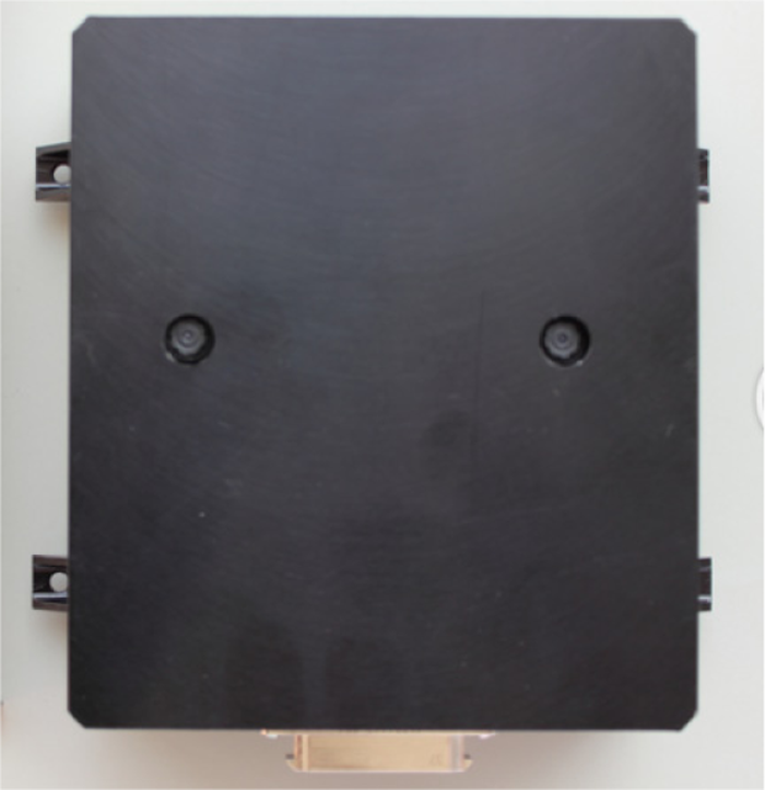
Embedded system.
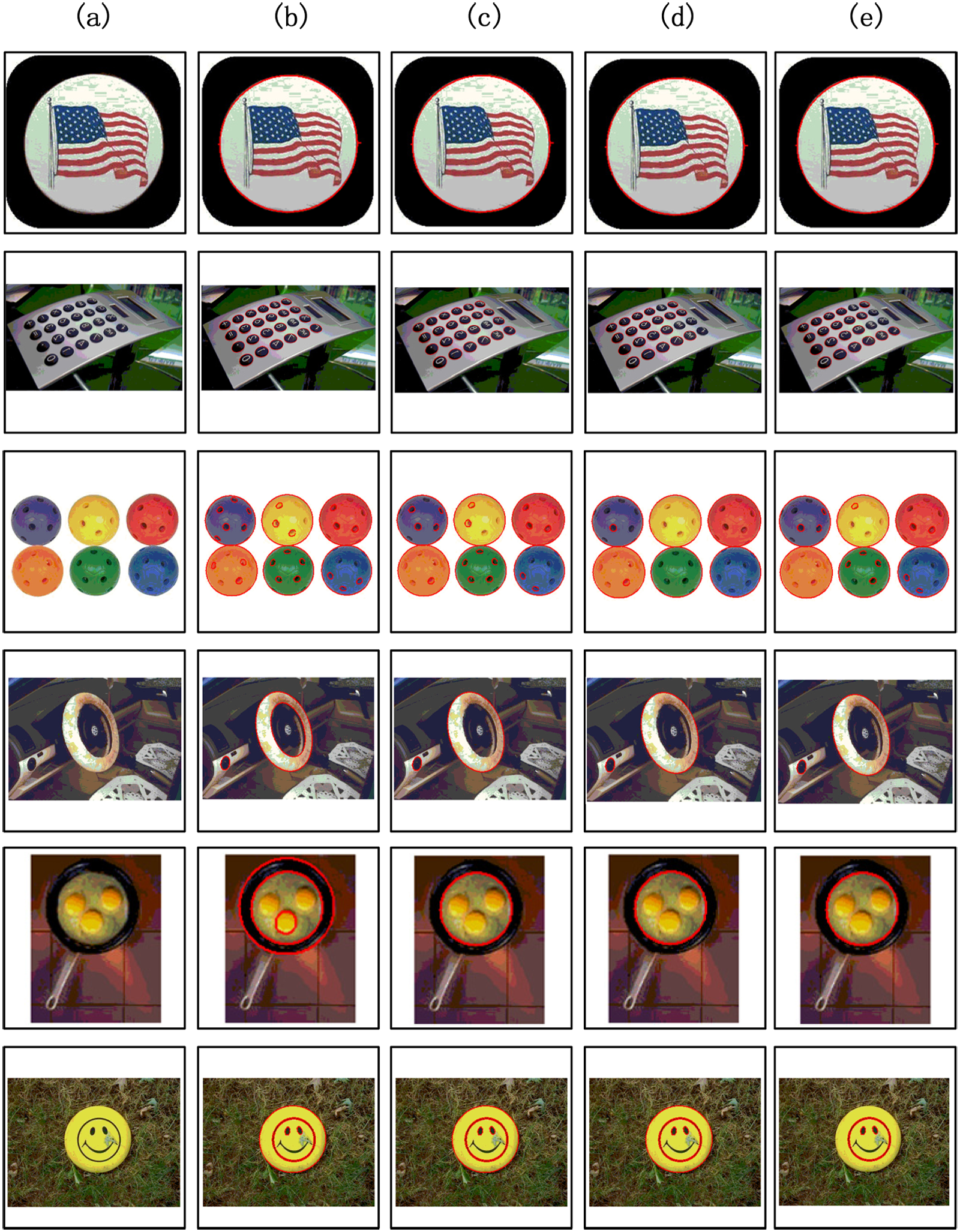
The average F-measure at different distances is shown in Figure 18, while average image shooting time at a short distance is shown in Table 3. Some detection results of the compared methods are depicted in Figure 19. It seems that Liu and Qiao 22 method cannot detect correct ellipse for the reason mentioned above. And the performance of Prasad et al. 17 and Fornaciari et al. 20 methods is inferior, especially for image shooting at a short distance. This is mainly because the large ellipse is more likely to break into a set of edge contours with small integrity, and large error may occur at the calculated center of ellipse. The proposed method is the best in terms of effectiveness and computation time. It is worth noting that the proposed method performs best for image shooting at distance between 2 and 4 m since moderate edge points can be obtained, neither too much nor too little.
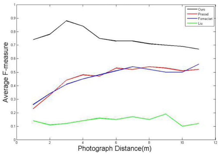
Comparison of performance of different methods in dataset II.

Examples of performance of different methods in real images (dataset II): (a) original ellipses, (b) our proposed method, (c) Prasad et al., (d) Fornaciari et al., and (e) Liu and Qiao.
The execution time (represented by updating rate) at different distance in embedded system is shown in Figure 20. As expected, the execution time is inversely proportional to the distance because the number of edge points decreases as the shooting distance increases. And it demonstrates that the proposed method can achieve real-time ellipse detection for embedded application.
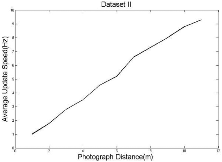
Execution time in embedded system.
Conclusion
This article proposes a novel and effective method for ellipse detection, which is suitable for large-resolution images in various embedded systems. First, smooth edge contours without any branches are extracted, a new edge contour detection method is employed to reduce time and space complexity, and segmentation and merging is performed to obtain the smooth contours. Second, three conditions are proposed as a pair selection method to group edge contours that belong to the same ellipse. The results show that the performance of the proposed method is superior in both effectiveness and computation time, and it is a real-time algorithm for embedded system with limited computational and memory resources.
Footnotes
Academic Editor: Francesco Massi
Declaration of conflicting interests
The author(s) declared no potential conflicts of interest with respect to the research, authorship, and/or publication of this article.
Funding
The author(s) received no financial support for the research, authorship, and/or publication of this article.