
Abstract
A robotic chair/bed system for assisting bedridden aged for their independent life in bed is developed and tested. This robotic system can assist bedridden people to lead a relatively independent life, so as to relieve the burdens for their families and healthcare personnel. The robotic chair/bed system consists of a reconfigurable and omnidirectional mobile chair/bed and a U-shaped bed. The wheelchair can be docked to the U-shaped bed and reconfigured to a static bed for transportation between chair and bed. A six-wheel omnidirectional vehicle is used for the chair/bed. The bed is equipped with a mechanism for repositioning a rigid body with a flexible sheet to alleviate bedsores and other ailments. Through the teleconferencing facility on the bed, the bedridden patient is supervised and assisted all the time by the distal caregiver. The design concept of the chair/bed system is described in short. The mechanism design and analysis of the vehicle, the flipping-body function, and the chair/bed are discussed. The issue of the docking control is addressed. A prototype system is designed and tested. The technical feasibility is verified.
Introduction
In recent years, the number of the elderly people who need to stay in bed for a long time has increased rapidly. Besides, many people have difficulty in walking or taking care of themselves, due to traffic accident or born deformity. In today’s healthcare activities, the most laborious task is the transferring of bedridden people, that is, transferring between the bed and the wheelchair. 1 It is an extremely laborious, physical job, which average people are unable to perform without the use of special equipment. 2 Therefore, a device that can transform between the care-bed and the wheelchair easily and smoothly is urgently needed.
Patients confined to the bed for a long period of time need to be periodically turned and repositioned to avoid painful bedsores and pneumonia. 3 Bedsores are formed due to lack of blood perfusion caused by local pressure concentrations on a bedridden body. An effective remedial measure is to reposition the patient at regular intervals to ensure frequent pressure redistribution. 4 A number of studies show that regular turnover not only prevents bedsores efficiently but also helps improve breathing conditions, prevent respiratory and cardiac arrest, and release the oppressed of bones and organs. 5 In fact, people always change sleeping position and posture without consciousness as they fall asleep soundly. However, due to physical limitations, most of the elderly people and the disabled are unable to alter sleeping pose independently. 6 Therefore, turning bedridden people regularly is considered the most important function for healthcare device.
Some previous work has been done, such as the TotalCare Beds designed by Hill-Rom Company, the Acute Care Hospital Bed-TB produced by Tautmann in Turkey, and the Völker Multifunction nursing beds designed in Germany. However, this article has proposed a totally different hybrid chair/bed system. Serving both as a wheelchair and a bed, this robotic system can meet the needs of transferring and repositioning bedridden patients automatically. When used as a wheelchair, it can help the patient move around freely. When used as a bed, this robotic system can help reposition the patient in a commodious space. Also, the autonomous tracking and laterally moving function have improved the system’s stability and reliability. It can assist bedridden people to lead a relatively independent life, so as to relieve the burdens for their families and healthcare personnel.
Design concept
Figure 1 shows the schematic of the robotic chair/bed system, consisting of a reconfigurable, omnidirectional mobile chair/bed, a U-shaped bed, and a computer on the bed. The chair is reconfigurable to be a flat bed or a couch with a reclining back and a foot rest and is omnidirectional when being detached from the bed to transport the bedridden person or docked to the bed automatically. Evidently, the system can be transformed between bed mode and chair mode. The wheelchair is narrow enough to go through residential doors and to maneuver freely within a crowded room; meanwhile, the bed is wide enough to prevent the patient from falling out and to provide comfort. In the bed mode, patients can be periodically turned over and repositioned automatically to avoid painful bedsores and pneumonia. So from the view of comfort, this system has been well designed to satisfy the need of users.

The schematic of the robotic chair/bed system.
When the bedridden person wants to move out, the back of the chair is first raised as the foot rest is folded down and then the chair detaches from the bed portion from sideways automatically. The reversed procedure can be performed, so as to transform the wheelchair back to the bed configuration. This process can be done automatically, thus it is practical and convenient.
Mechanical design
The six-wheel laterally movable vehicle
To dock the wheelchair to the bed from sideways, which is better adapted to the narrow space, the wheelchair must be capable of lateral motion and be positioned precisely against the fixture. The omnidirectional vehicles have been developed by different groups in the last several years, for example, the ball wheel mechanism, 7 the double-offset active caster wheel, 8 the Mecanum Wheel, 9 and the Swiss Wheel. 10 The vehicle mechanism used for the robotic chair/bed system is based on a special six-wheel mechanism, which has larger load capacity and almost no skidding and noise, allowing for precision docking and smooth and silent motion.
Figure 2 illustrates the six-wheel laterally movable mechanism. The vehicle has two chassis. The driving chassis supports the two driving wheels which are driven by two geared motors, respectively. When the speed is isokinetic reverse, it can achieve a zero radius of rotation. The supporting chassis supports four driven wheels which can enhance stability and load capacity. Between the driving chassis and the supporting chassis, there is a rotary axis with a built-in electromagnetic clutch. The electromagnetic clutch can control the connection and separation between the driving chassis and the supporting chassis.

The mechanical structure of the vehicle and the rotary axis subsystem.
The process of the laterally movable movement is shown as follows: first, the electromagnetic clutch is separated; the driving chassis rotates 90° while the supporting chassis remains stationary. Then the clutch is connected so that the supporting chassis can move and rotate with the driving wheels and the vehicle can move sideways. With this special mechanism, the vehicle is capable of moving laterally.
Flipping-body function
The current practice in nursing homes and hospitals involves nursing personnel, who move the patients manually. 11 This is a fairly heavily manual labor requiring at least two caregivers for each bedridden, and the repositioning operation is very time-consuming. 12
There are a few commercially available beds that meet some requirements of patients, such as Hill-Rom 13 and Kinetic Concepts, Inc. 14 Some researchers use air mattress 15 or mechanism16 to meet the demand. However, these beds have not been widely used due to high cost, complexity, and limited performance. To design a more effective and comfortable device, we have studied the regular steps involved in manual repositioning of a bedridden patient in nursing home. A simple robotic device is developed and analyzed as a natural extension of the manual repositioning procedure.
Figure 3 shows the cross-sectional view of the body–sheet interaction. To make matters simpler, the following assumptions have been proposed:
The body has only a little slip on the sheet.
The movement is so slow that the system is in quasi-static equilibrium at all times.

Model of the flipping-body mechanism.
In the model,

As seen in the equations, the extended line of the gravity force mg and the line of the sheet tensions T intersect at the same point P.
Considering the free-body diagram of differential element ds of the sheet, the sheet element subtends an angle
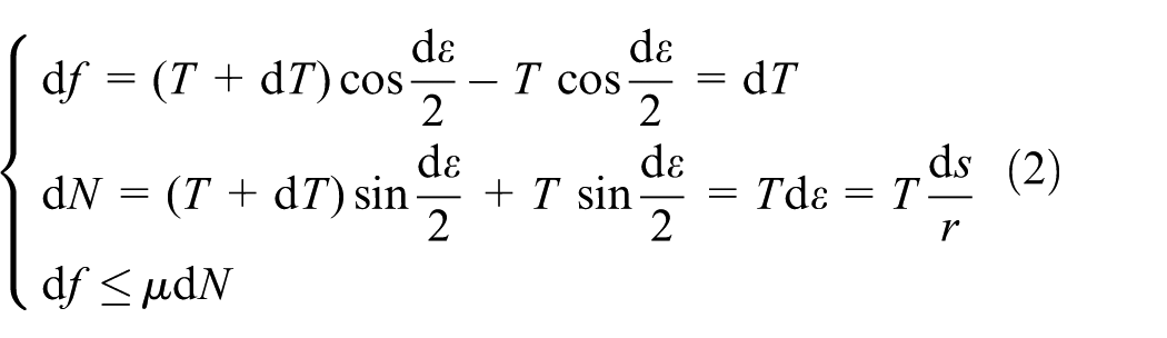
If the body does not slip on the sheet, we may integrate the above equation from A1 to A2

The relationship in the equation represents the sufficient condition for no slip to occur as a function of the friction coefficient and angles
Then we assume that the rigid body is shaped as an elliptical cylinder described by axial length a and b. Let

Combined with the previous analysis, we can get

Using the equations, this can be written as follows
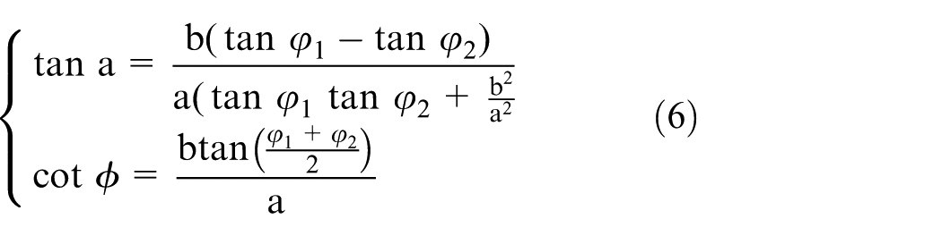
It is now possible to determine closed-form solutions for

where

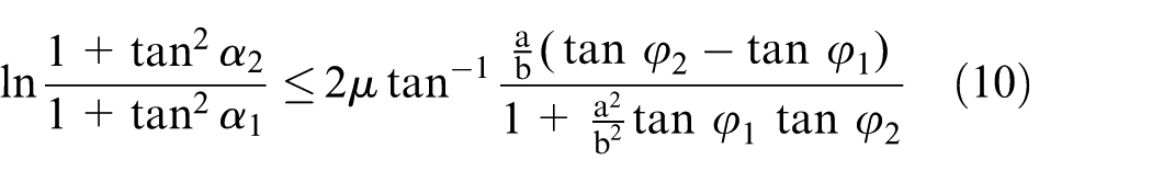
Using standard formulas for an ellipse, we may write

Using the equations above and assuming a constant coefficient of friction, we can get
Now we can analyze more about the angle of beam

where

Considering the linear actuators, the kinematic configuration of a pair of 1-degree-of-freedom beams with linear drivers can be shown as follows
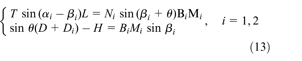
From the above analysis, we can get the relationships between the angle of the body
Figure 4 shows the mechanism of the bed and the flipping-body system. The backplane portion of the robotic chair/bed system is divided into two floors. To avoid moving the body, the upper floor consists of two parts—the right flipping mechanism and the left flipping mechanism, which are composed of a number of beams, connected to the lower floor by hinges. On the surface of the upper floor, there is a soft sheet, connecting the right and the left mechanisms. The mechanisms are mutually crossed; their axes are, respectively, located on the right and left sides of the patient’s shoulders axis. In the chair mode, the flipping-body function cannot be used. To reduce the size and weight, the electric linear actuators which move along the direction of the beam are fixed on the U-shaped bed, under the backplane in the bed mode. On the top of the actuator, there is a steel roller. One beam of the right/left mechanism is above the roller; its underside is made of magnet. When the actuator is at the initial stage, the roller does not contact with the beam. When the actuator is pushing, the roller will contact with the beam and drive the beam rotating around the hinge. The flipping mechanism raises one side of the sheet and the patient is turned. In this process, the roller is reciprocating on the beam. After the patient is propped with pillows, the mechanism moves back, and the roller and the beam are still in contact because of the gravity and magnetism. When the mechanism is leveled down, the lower floor can prevent the mechanism from rotating downward, and the roller will separate from the beam pulled by the actuator. There is a notch on the beam, and it is wide enough to prevent accidental slide of the roller. The proposed method merely places the human body on a bed sheet, with no unsecure contact between the robot endpoint and the human body, and the patient’s body can be turned comfortably and safely.

The flipping-body mechanism and the actuators.
A reconfigurable chair/bed
The reconfigurable chair/bed mounted on the vehicle can recline and raise the back as well as fold and extend the foot rest. When the back rises, the body of the patient tends to slip down. When the robotic chair/bed system is in the chair mode, the patient needs a place to rest the feet. To meet these requirements, a reconfigurable chair/bed with 2 degrees of freedom and linkage mechanism has been designed, as shown in Figure 5. The leg and the back can be raised gradually, pushed by the linear actuators, so that the chair/bed can be used for assisting the elderly people in sitting and lying. A free plane is attached to the seat portion by a hinge, which is supported by the mechanical limit so that it cannot rotate down when the patient sits on it. Below the plane there is a pendulum with a roller on the top, connecting with the backplane by a link. The roller does not contact with the seat plane in the bed mode. When the backplane rises, the pendulum rotates up and the roller will contact with the seat plane. If the backplane continues to rise, the seat plane rises pushed by the roller, so that it can prevent the body slipping down from the chair. As in the bed mode, the seat plane can be laid flat to be a comfortable bed. The foot rest is designed to connect with the leg plane by a hinge and with the seat by a link. Since a parallel four-bar linkage has been formed, the foot rest always parallels to the seat surface when the leg plane moves, due to which the foot rest can become a part of the bed in the bed mode and rest the feet in the chair mode.

The reconfigurable chair/bed.
Docking control
The central to the concept is that the wheelchair is docked to the bed automatically. The critical function of the vehicle is to be positioned against and mated with a U-shaped bed accurately in an indoor environment. So, there are a few unique issues in our system.
The vehicle carries the patient, so jerk and impact during the docking operation must be minimized in order to maintain a comfortable ride. To satisfy this requirement, a bumper has been fixed on the bed. Namely, the bumper can absorb the impacts during the docking process. The vehicle is equipped with sensors measuring contact with the bumper, and it can change the direction or fully stop controlled by different signals.
The vehicle, when fully loaded, may not be driven backward on the smooth ground, due to which the laser finder is chosen as the major sensor for docking. The sensor can detect the shape of the bed and calculate the position and angle relative to the bed. The accuracy of this absolute positioning method is not influenced by the relative positioning error and the wheel slip.
During the docking process, the driving chassis is rotated. A potentiometer is used to detect the rotation angle so as to ensure the accuracy of the moving direction.
The docking and undocking are performed automatically according to the patient’s command. During the process, the patient is allowed to stop or reverse the process at any time. To guarantee safety, the process is supervised by a caregiver at a distant nursing center. The U-shaped bed is equipped with a computer (connected to a camera, microphone, and monitor), which could control the chair/bed by wireless serial port. The caregiver at the nursing center can be accessed from the robotic chair/bed system through the Ethernet. The computer can also provide entertainment and Internet access to the patient.
Implementation and experiment
Figure 6 shows the overall view of the robotic chair/bed system developed by Beihang University. The system consisting of a vehicle, chair/bed, and U-shaped bed was designed for standard residential homes. The vehicle can go through standard doors of 80 cm in width and turn within a small space of 120 cm in diameter. The vehicle can go over a step lower than 10 mm and climb a ramp way of up to 10°. The maximum payload is 250 kg, including the equipment up to 100 kg. The rated speed of the vehicle is 3 m/s. It can be used on wooden, linoleum, hard carpet floors, tile floors, and gravel road.

The overview of the robotic chair/bed system.
Figure 7 shows a photograph during the rolling operation of the flipping-body mechanism. First, both arms of the patient are placed on the chest. Then one flipping mechanism is upward rotated of more than 90°; at the same time the other flipping mechanism is upward rotated of about 15°, and the patient is repositioned by the flexible sheet. Finally, the patient is propped with pillows, and the mechanism moves back to the horizontal position.

The rolling operation of the flipping-body mechanism.
Figure 8 shows the angular displacement function of the flipping mechanism and the roller displacement on the beam when the actuator is pushing out at 10 cm/s. It can be seen that, if it is necessary, the mechanism can be rotated 96°. The mechanism is specifically optimized, so that the roller is reciprocating on the beam, and the total trip is merely 34 mm. This can minimize the impact of the docking error and the probability of roller–beam separation.

The angular displacement function of the flipping mechanism and the roller displacement on the beam.
Figure 9 shows the driver force function and the energy dissipation function. It can be known that the force and energy dissipation increase at the beginning, and then decrease almost to zero near the end. During the motion, the angle between the actuator and the bed board first increases to 90° and then decreases, but the angle between the load force direction and the bed board always decreases. When the mechanism is rotated over 90°, the load almost vanishes, and the force turns to be zero. Therefore, it can be learned that the movement matches the expectations, and the linear actuators meet the demand.

The driver force function and the energy dissipation function.
Figure 10 demonstrates the docking process of the robotic chair/bed system. In the chair mode, a patient drives the wheelchair near the bed portion, and the side of the vehicle, which is equipped with the laser finder, faces the opening of the bed. Then the driving chassis is rotated and the vehicle is guided to the bed automatically. After that the back of the chair is lowered and the foot rest is raised. By the time the vehicle has docked to the bed portion, reconfiguration has been completed, and the system is in the bed mode. The undocking procedure is simply reversed.

The docking process of the system: first, the patient drives the wheelchair near the bed portion, then the driving chassis is rotated and the vehicle is guided to the bed automatically, and finally the back of the chair is lowered and the foot rest is raised.
Conclusion
A hybrid robotic chair/bed system has been developed. An omnidirectional vehicle with six wheels and a new mechanism for repositioning the patient with a flexible sheet have been discussed, analyzed, and simulated in detail. These mechanisms have been applied to a rehabilitation chair/bed for repositioning and transferring patients. A docking control method using a laser finder has been designed and tested. The system can partly help the elderly people for their independent life in bed and relieve the burdens for their families and healthcare personnel in the experiment, and the technical feasibility is verified. There are also some future works: A one-key automatic separation function and a voice control function will be added to the system. Thus, the system will be more intelligent and convenient to the users. The robotic chair/bed system has been successfully tested and implemented in SiJiQing nursing home in Beijing.
Footnotes
Acknowledgements
The authors would like to thank the patients and nursing assistants of the SiJiQing nursing home in Beijing for their help and advice with this project. The authors would like to thank the anonymous reviewers for their detailed and insightful comments regarding this work.
Academic Editor: Yangmin Li
Declaration of conflicting interests
The author(s) declared no potential conflicts of interest with respect to the research, authorship, and/or publication of this article.
Funding
The author(s) disclosed receipt of the following financial support for the research, authorship, and/or publication of this article: This work was supported by the Natural Science Foundation of Jiangsu Province, China (Grant No. BK20160185), the Fundamental Research Funds for the Central Universities (Grant No. JUSRP11718), and the Foundation of Jiangsu Key Laboratory of Advanced Food Manufacturing Equipment and Technology (Jiangnan University).