
Abstract
We have developed a pair of step-climbing units that can be installed on a standard manual wheelchair. Many wheelchair users hope to lead an independent life without assistance. The target users of these units are those who can independently lift the front casters of their wheelchairs. The units are installed on the back frames of a wheelchair. Each unit comprises two actuators and has 2 degrees of freedom: telescopic motion and rotational motion. They are lightweight and do not prevent the wheelchair from being folded. Therefore, it is still relatively easy to load a wheelchair fixed with these units into a car. In our earlier project, these units addressed the problem of climbing a single step. In this article, we primarily discuss a strategy that enables wheelchair users to climb stairs comprising multiple steps. We additionally use a pair of portable slopes to achieve this task. Results of experiments where users traveled on a pair of slopes that covered a height of 30 cm over two steps confirm the effectiveness of the design.
Keywords
Introduction
Persons with disabilities attributable to the lower limbs are becoming increasingly numerous worldwide. The Cabinet Office, Government of Japan estimated that disabled persons were 3,937,000 in 2014. 1 The ratio of the physically handicapped persons was about 50.5% (1,988,000); approximately 12.3% (245,000) of them were wheelchair users according to the data of the Ministry of Health, Labour and Welfare. 2 Moreover, considering the rising tendency of aging population, it is anticipated that wheelchair users have increased continually. Along with the recent development of remarkable robotic technologies, many researchers are striving to apply those breakthroughs to rehabilitation.3–5 Various devices and robots have been developed, mainly to alleviate burdens of caregivers and to promote the self-support of disabled and elderly people. Many devices and robots, however, have been produced only on an experimental basis.
One representative assistive product for disabled people is a wheelchair. Most people with disability of lower limbs use wheelchairs because of their high maneuverability, stability, and wide availability at low cost. Nevertheless, wheelchairs have their shortcomings: traveling on uneven ground, for example, a step or a steep slope, is difficult; wheelchairs necessitate the use of a multipurpose toilet; and difficulty in accessing high places and mental stress result from the low eye position of the user. Particularly, a worker using a wheelchair has strong demands related to the first problem because steps at a home or store entrance might prevent a wheelchair user from entering.
Various mechanisms for lifting wheelchairs have been proposed to solve difficulties in coping with surmounting steps. They are roughly classifiable into the following two types: (1) for front casters and (2) for all casters and wheels. Many mechanisms have been proposed for the lifting of front casters. Kato proposed an arm of a circular arc installed on the frame between the front casters of a wheelchair. This arm lifts the front casters automatically when the wheelchair goes forward to a low step. 6 Yokota et al. applied a similar mechanism to each front caster of the wheelchair and added an electromagnetic brake. The prototype wheelchair climbed a 50-mm step with an oblique approach. 7 Most wheelchair users, however, are able to lift the front casters stably. Moreover, they are able to maintain the balance of their position through training at a rehabilitation center.
For systems using all the casters and wheels, (2), their targets are two types: (1) for a step and (2) for stairs. For the former, Yamazaki et al. proposed a four-legged mechanism, applied to “Angle-mam” produced by Yamatomech Co., Ltd. 8 This mechanism realizes a stable up/down motion, but it is large. A caregiver is needed because the wheelchair with this mechanism cannot be propelled when lifting the wheelchair. Takahashi et al. 9 applied an inverted pendulum to an electric wheelchair that can balance with the front caster lifting and which can surmount a 10-cm step. Wada et al. developed a chair-tilting mechanism installed on a four-wheel-drive (4WD) omnidirectional wheelchair. The wheelchair climbed a 9-cm step. 10 Ikeda et al. proposed a step-climbing method: a height-adjustable link connects two wheelchairs. Then, the wheelchairs mutually cooperate. 11 Some problems remain in these mechanisms in terms of the applicable environments and conditions. J-MAX, which has two telescopic legs and which realizes smooth and continuous climbing motions, is an example of “for stairs.” 12 Although J-MAX is of great practical use, it requires a specially designed wheelchair and a caregiver who is trained to handle this system. Some stair-climbing wheelchairs, of which iBOT is a representative product, have been developed. 13 Yanagihara 14 developed a stair-climbing wheelchair with four cluster wheels. Fang et al. 15 proposed such a wheelchair with two cluster wheels on its front. Other wheelchairs have been developed with mechanisms using crawlers and links.16–23 These wheelchairs have excellent properties for uneven ground. However, they are specially designed and some room remains for discussion to find the best wheelchair type for a wheelchair user who lives mainly in flat environments.
We proposed a pair of step-climbing units for a manual wheelchair user based on actual demands. We aim to extend the range of action of wheelchair users who have no caregiver. We demonstrated that the user could ascend and descend a step having a height of 15 cm.24,25 However, stairs comprising several steps in front of homes and stores are common. In this article, we present a method to pass over several steps using a pair of portable slopes. The second section presents the conceptual design of this unit. Kinematics and the basic equations are presented in the third section. The fourth section explains the design of the unit. We discuss the experimental results when traveling on a slope in the fifth section. Concluding remarks follow thereafter.
Conceptual design
An assistive device for steps greatly expands the sphere of activity of wheelchair users and supports their independent life. Our research concept is described as follows.
Target users of this system are manual wheelchair users.
The units of this system can be attached to a conventional wheelchair as a retrofit.
The mechanism is simple because it makes use of the wheelchair user capabilities.
The mechanism prevents a user from falling backward by supporting the wheelchair from the rear.
First, regarding concept (1), some steps exist all over the environments even if barrier-free designs have been promoted. They present barriers to a wheelchair user’s activity. Assistance for the wheelchair imposes a burden on a caregiver. The wheelchair user might sometimes feel it to be a mental burden. Therefore, step-climbing ability without a caregiver present is important, especially for active wheelchair users. We choose the maximum height of the target step as 15 cm because most entrance step heights of stores and buildings are less than 12 cm, as Ikeda et al. 26 pointed out. In terms of concept (2), many wheelchair users use each customized wheelchair fit to personal physical traits. This merit is also effective to prevent pressure ulcers of the buttocks. Concept (3) is effective for practical use. The ability to lift the front casters contributes to the lightweight, the compact size, easy maintenance, and so forth. Concept (4) is related to the safety. Some supporting mechanism from the rear is indispensable when climbing the step.
We have proposed a pair of step-climbing units for a manual wheelchair user that satisfy the above conditions as shown in Figure 1. Each unit comprises two actuators and has 2 degrees of freedom: a prismatic joint and a rotational joint. Those units are installed on the back frames of the wheelchair. They do not prevent the wheelchair from being folded. It is therefore easy to carry the wheelchair with units by a car.
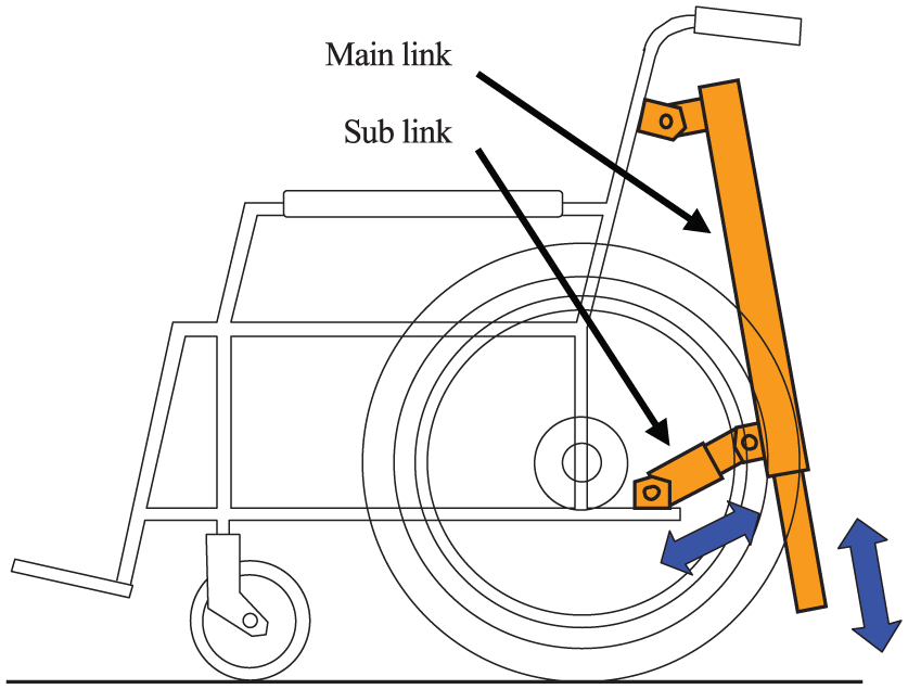
Conceptual design of the step-climbing unit.
Kinematics of the system
This section describes the kinematics of the wheelchair with the step-climbing units and the trajectory generation. Figure 2 presents a model of the hardware. The following variables are incorporated into the model.

Model of the wheelchair with step-climbing units.
Forward kinematics
When variables


In those equations,
Angle
Therein,

Angle

Therefore, angle

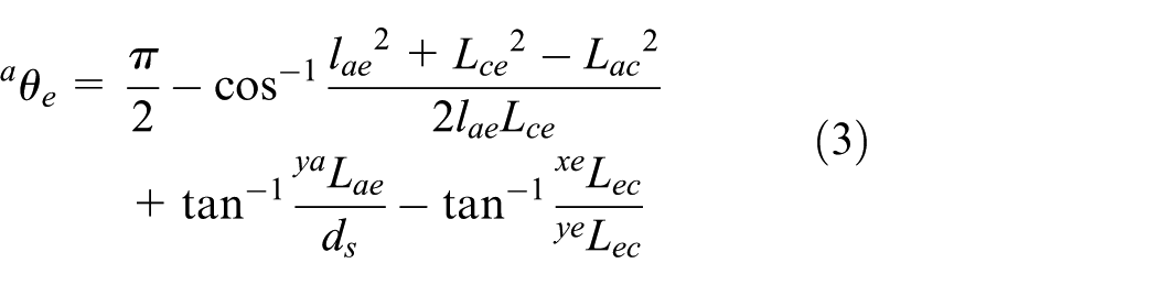
Inverse kinematics
Variables


In equation (7),


In those equations, the tilt angles of the wheelchair

Next,

In the equation above,

In that equation,


Trajectory generation when traveling on a pair of slopes
Figure 3 depicts the model applied when a wheelchair travels on a slope. The tip of the main link moves from the position of


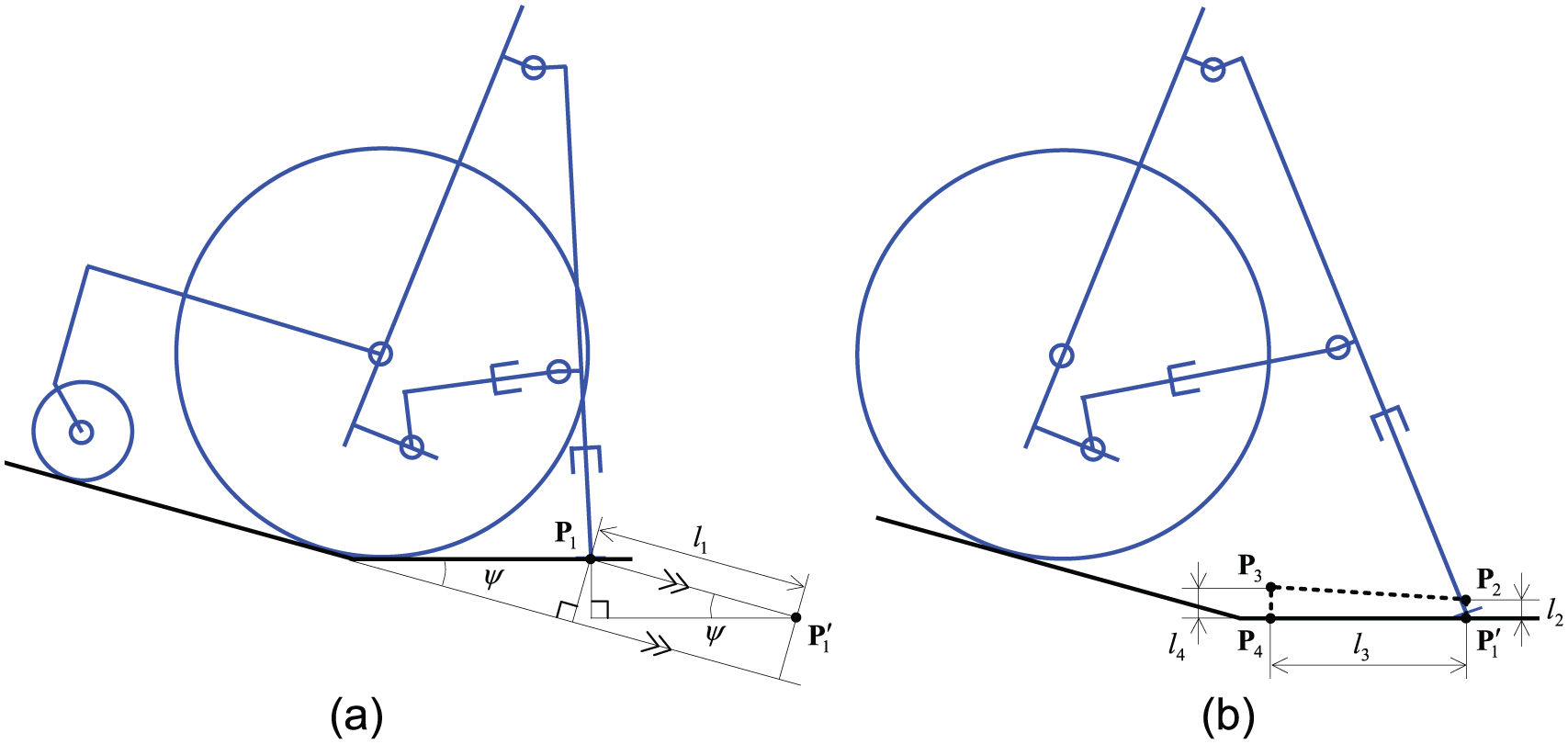
Model for generating trajectory when traveling on a slope: (a) when climbing up a slope and (b) when moving the legs.
Actually, the wheelchair is pushed up by the main links because the tips of them are on the floor as shown in Figure 3(b). After that, the tip of the main link moves
Hardware
We next describe the design of hardware that realizes the step-climbing motion. Newton–Euler equations are applied on the condition of a quasi-static model.
Calculation for the hardware
The following numerical values are assigned to each variable:
g: gravitational acceleration;

Model for dynamics analysis.
The equations of motion for the main link are given as presented below


Below are the equations of motion for the sub link


The equations of motion for the wheelchair (including a human user) are given as the following


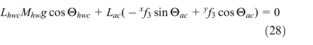
The floor reaction forces are derived from the equations above and the following equation (29) on the equilibrium of moment and equations (30) and (31) on the equilibrium of force for the whole system as the following


Therein,
Finally, the propulsive forces are derived as the following


In those equations,
Figure 5 depicts the calculated results of

Relationship between the distance from
Design of the hardware
Figure 6 presents the appearance of the wheelchair with a pair of step-climbing units. The main link size is 12.0 (L) × 5.0 (W) × 65.5 (H, minimum length) cm. That of the sub links is 30.2 (L, minimum length) × 8.3 (W) × 10.0 (H) cm. The weight of the pair of units is about 2.9 kg. A standard manual wheelchair (16.8 kg; Nissin Medical Industries) is used for these experiments.
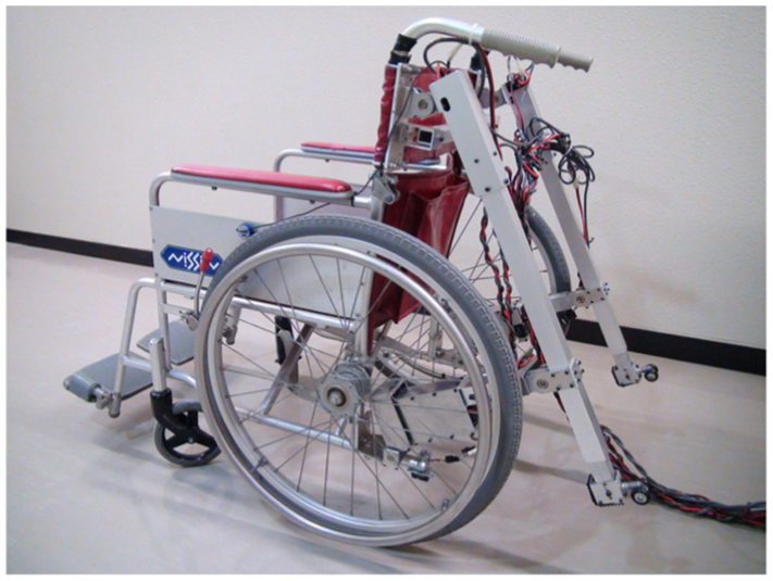
Wheelchair with a pair of step-climbing units.
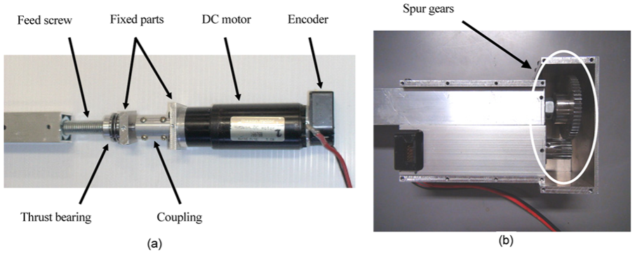
Figure 7 shows the internal mechanism of the main link. This link has one direct current (DC) motor (RE-40, 70 W; Maxon Motor) with a planet gear (reduction ratio = 1/5.8), an optical encoder (500 pulse per round), and a feed screw (length = 46 cm, diameter = 10 mm, lead = 1.8 mm). The main link total length is 65.5 cm (
Mechanism of the links.
The sub link is located on each side of the wheelchair using its tipping lever. The basic internal structure is the same as that of the main link. However, the motor is located parallel to the feed screw using spur gears (reduction ratio = 1/3.375) to design the link length as short. The extensional force of the sub link is 1675.7 N for one side if the transmission efficiency of the spur gear is estimated as 0.98. Twice the value of this force satisfies the condition of the required force (844 N) for the sub link. The maximum extensional velocity is 0.85 cm/s. The total length of the sub link is 30.2 cm (
Specification of the telescopic links.

The way to fix the links of two types to the wheelchair is described next. Those links must be attached to a conventional wheelchair afterwards. In addition, the following condition is preferred:
No machining process is necessary to fix them.
The wheelchair can be folded after fixing them.
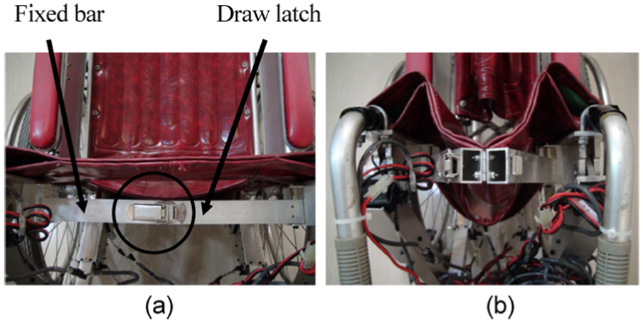
A free joint connects the main link to mount parts attached to the backrest of the wheelchair using a U bolt; and another free joint connects the sub link to mount parts attached to the tipping lever of the wheelchair with air hose bands. Figure 8 shows a support bar attached to the wheelchair backrest as reinforcement. Free joints on its ends are connected to the wheelchair. It can be bent in the center. Therefore, this bar does not prevent the wheelchair folding function. A snap lock attached in the center fixes the bar when closed. The configurations when expanded and folded are shown in Figure 8(a) and (b), respectively.
Mechanism of the support bar (top view): (a) when expanded and (b) when folded.
Figure 9 shows the tip of the main link that can switch the contact friction against the ground surface. When traveling with the front casters being lifted, the small caster contacts to the ground because the main link is in a vertical position. Therefore, the wheelchair can travel smoothly. However, when climbing up and down a step, the rubber contacts to the ground and the main link can obtain large friction force from the ground.

Mechanism of the tip of the main link: (a) when moving and (b) when standing.
Experimental verification
We next address the experimental results obtained when climbing up and down a step. The subject was a man with no leg motion impairment. His height was 158 cm. His weight was 55 kg. We used ART-Linux as the operating system because of its stability. The PC (CPU 1.1 GHz, Pentium M, Libretto U100; Toshiba Corporation) had an interface board (Ritech Interface Board IF-0145-1; Zuco); the motor driver was an HRP Motor Driver (HRT07-0004; Zuco). We measured the wheelchair tilt angle using an inclinometer (NA4-70, measuring range ±70°, resolution < 0.01°; Seika Mikrosystemtechnik GmbH). Each link was controlled based on proportional–derivative (PD) control theory; the sampling time was 5 ms. The step was made of concrete blocks and a wooden board. Its height was 15 cm. Experiments were conducted in an indoor environment on a linoleum floor surface.
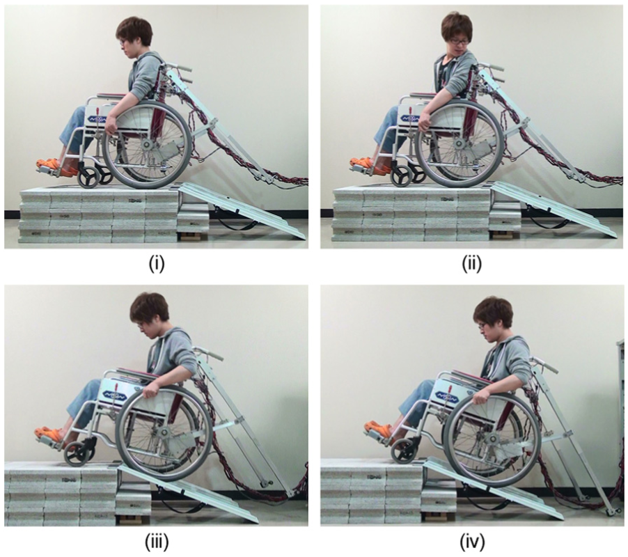
Figure 10 shows snapshots taken when going up a slope. We used a pair of portable slopes (Para Rail 90, 90 cm length, 18 cm width; Tsudakoma Corporation). Figure 11 shows the time response of the main and sub links on the right side when ascending a slope. The user carried the slopes, which were put on a right footrest of a wheelchair, as shown in Figure 12. The slopes were set on stairs of which the first step was 16 cm from the floor. The second one was 30 cm from the floor. Each tilt angle was about 20.7°. The sequence of this motion is the following. The Greek characters of each item given below correspond to those shown in the panel in Figure 10.
The user measured the step height using a measuring tape while seated on the wheelchair and inputted the data into the PC. Then, the user approached the wheelchair until just before the slope.
The main and sub links were adjusted to the initial positions for ascending a slope, respectively.
The main and sub links gradually pushed the wheelchair 42 cm up along the slope (in Figure 3,
The user applied the brakes of the wheelchair. Then, the main and sub links of the left hand moved horizontally along the floor. First, the tip of the main link moved 3 cm upward vertically, moved 38 cm horizontally, and 3 cm upward vertically (in Figure 3,
The main and sub links of the right hand moved similarly to phase (iv).
Both links pushed the wheelchair 18 cm up again along the slope.
The user released the brakes. Then, the user traveled forward independently to the top of the slope.
The links were reset to the initial positions.
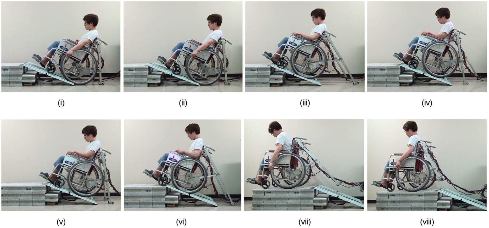
Photographs showing slope ascent.

Results of slope-ascent experiment: (a) time response of the length of the main link, (b) time response of the length of the sub link, (c) time response of the current of the main link, (d) time response of the current of the sub link, and (e) time response of the tilt angle of the wheelchair.

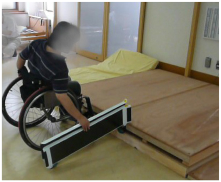
Carrying a portable ramp for a slope.
The Greek characters in Figure 11 correspond to those in Figure 10. The intervals are the following: (ii) 0–3.0 s, (iii) 3.0–31.0 s, (iv) 31.0–70.0 s, (v) 70.0–104.9, (vi) 104.9–127.1 s, (vii) 127.1–136.4 s, and (viii) 136.4–161.4 s. The user pressed a push-button to send the signal to the PC. It was pressed four times in (i), (iii), (iv), (v), and (vii). Figure 11(a) shows that the main link can follow the target with the maximum error of 1.6 mm (t = 103.9 s). The sub link also follows the target with the maximum error of 2.0 mm (t = around 111.5–112.8 s) (see Figure 11(b)). Figure 11(c) and (d) shows the current of each link. The maximum and minimum values of the main link are 2.64 A (t = 109.3 s) and −0.39 A (t = 72.3 s), respectively, and those of the sub link are 0.30 A (t = 109.5 s) and −0.53 A (t = 75.4 s), respectively. Figure 11(e) shows the time response of the wheelchair tilt angle. Large fluctuations were generated during (vi)–(vii) when the wheelchair was moved independently by the subject.
In (i), the wheelchair user him/herself puts the portable slopes on steps while seating. We have confirmed that actual wheelchair users can realize the motions of putting and picking back the portable slopes (see Figure 13). This task is not all that difficult if light portable slopes are used. The main link slipped on the floor about 11 cm in (iii) and about 3.7 cm in (vi). We consider the following as a countermeasure against slipping: (1) repeat the pushing-up motion and (2) expand a rubber sheet folding on each slope when installing it to the stairs.
Photograph showing that an actual wheelchair user is putting the portable slopes on a step.
Figure 14 presents snapshots taken when descending on a slope. The main and sub links were set to the expanded positions as shown in (i). Next, the user confirmed the slope positions in (ii). The user grasped both wheelchair wheels firmly and went backward gradually in (iii). The wheelchair stopped descending because the main links supported it as shown in (iv). The position of (iv) was similar to that of (iv) in Figure 10. Thereafter, each link followed the inverse sequences in Figure 10.
Results of slope-descent experiment.
We examined this system for use in outdoor environments. As a result of the examination using the part of the main link removed from the system, less slippage occurred on the asphalt surfaces, which are the environments most likely for use, than on the indoor linoleum surface. Even if a small amount of sand was on the asphalt surface, the slippage condition was almost the same because of the roughness of the rubber surface of the main link tip.
Conclusion
We proposed a pair of step-climbing units for a manual wheelchair user. They are installed on the back frames of the wheelchair and prevented the user from falling backward. The units do not prevent the wheelchair from being folded. Therefore, it is easy to carry the wheelchair with units by a car. In this article, we used a pair of portable slopes to pass over several steps. The kinematics, trajectory generation, and dynamics of this system were presented. We demonstrated that the user can travel over a pair of portable slopes that cover a height of 30 cm over two steps.
In future works, we plan to improve this system for better practical use. The time for climbing steps will be improved if we use higher speed and power motors. The measuring process of the step height will be automated by using an inclinometer and a Bluetooth module that are installed in one of the slopes. We will attempt to use it in various actual environments.
Footnotes
Acknowledgements
We thank Akihiko Nakada, Tamio Moribe and Naohiko Okumura for the helpful discussions, and Hiroki Sasahara for the experiments. We also thank the reviewers for several comments to correct and improve the paper. This work was funded in part from TSUDAKOMA Corp.
Academic Editor: Duc T Pham
Declaration of conflicting interests
The author(s) declared no potential conflicts of interest with respect to the research, authorship, and/or publication of this article.
Funding
The author(s) received no financial support for the research, authorship, and/or publication of this article.