
Abstract
In aircraft assembly, the influence of interlayer burr formation in drilling of stacked metal sheets is an important problem. This article aims to develop a deeply understanding of the relationship between the clamping force and interlayer burr formation. The minimum clamping force, which would just make the stacked sheets entirely contact each other, is considered as the optimal clamping force. Hence, the additional deformation would appear at the contact region when the clamping force keeps rising up. The optimal clamping force is obtained first through theoretical calculation. Then, numerical simulations and experimental verifications are conducted. The results demonstrate the effectiveness of the theoretical analysis based on shell theory.
Introduction
Mechanical connection is one of the important connection ways to fasten aircraft structure permanently. There are as many as 1,500,000–2,000,000 rivets and bolts in a modern large aircraft. 1 Traditional manual drilling is time-consuming and the hole quality is difficult to guarantee. Therefore, the robot drilling system has been widely applied in modern aircraft manufacturing industry.2–4
In order to improve the assembly quality and efficiency, one-side drilling operation is applied to drill different stacked combinations instead of drilling each layer material separately.5,6 The stacked structure makes the drilling process very difficult. One of the challenges is eliminating interlayer burrs. 6 Burr removing needs to disassemble the connection and reassemble after deburring. These additional operations are typically difficult to automate and are mostly done manually. 7 Gillespie 8 indicates that deburring can account for as much as 30% of the total part cost. Hence, burr formation control is an important part during aircraft assembly.
Numerous investigations have been conducted concentrated on burr formation and minimization in drilling stacked metal materials. Many researches point out that workpiece parameters, tool parameters, and process parameters have significant influence on burr formation. Most of the parameters are summarized in Table 1.4,9–17 Two-dimensional or three-dimensional finite element (FE) methods are introduced to study the mechanism of burr formation and evaluate the influence of the relevant parameters as well.7,18,19
Parameters related to burr formation.

Although a lot of work has done to control burr initiation during drilling stage, few researches focus on the effect of the clamping force on eliminating interlayer burrs. The inhibit mechanism of the clamping force on interlayer burr is still not clear. 20 Hellstern 21 conducted stacked sheets drilling test with specific clamping force. They concluded that the larger is the clamping force, the smaller is the burr. But they did not explain how to select the appropriate clamping force. At present, the value of clamping force is mainly dependent on empirical data. If the clamping force is too small, the effect of eliminating interlayer burrs would be undesired. On the other hand, if the clamping force is too large, local oversize deformation of the sheets may lead to quality problem.
This article aims to develop a deep understanding of the relationship between the clamping force and interlayer burr formation based on shell theory. The optimal clamping force is obtained after theoretical calculation, numerical simulation, and experimental verification.
Clamping force theoretical analysis
The stacked aluminum sheets drilling process can be generally divided into three stages. Stage 1, the drill bit works on the upper sheet, while the lower sheet undergoes interlayer force from upper sheet. Stage 2, the drill bit breaks through the upper sheet and reaches the lower sheet. The interlayer gap begins to rise gradually. Stage 3, the drill bit is engaged in the lower sheet. Then, the hole is completed. The burrs are mainly formed when a drill enters and exits the hole in stage 2, 9 as illustrated in Figure 1.

The sketch of stacked aluminum sheets’ drilling process.
During aircraft assembly, the sheets can be divided into numerous thin plates with four sides simply supported.
6
When drilling, the drilling thrust force and one-side clamping force will act on the stacked sheets. The forces will lead to different bendings of each sheet which would result in interlayer gap formation and variation. As shown in Figure 1, the clamping foot is a metal ring with external diameter


The simplified model with four sides simply supported.
Due to the application of the fixture, the deformation of the thin sheets with four sides simply supported is small during the manufacturing process. The solution of the bending of metal sheet belongs to plate theory. 22 L Jie 6 points out that the only difference between the beam theory and the plate theory is dimension. Therefore, the beam theory can be used to describe the relationship of interlayer gap and acting forces. As a result of the simplification, the deformations of the sheets can be described in terms of the deformations of the beams, as shown in Figure 3. 6

Stacked sheets’ beams.
In Figure 3, the unit force,
In stage 2, the upper and lower sheets do not contact each other. As illustrated in Figure 3, for lower sheet, the drilling thrust force,

where
For upper sheet, the clamping force,

where
Then, the interlayer gap,

where
When the workpiece structure and the drilling parameters are decided, the interlayer gap,

where
As shown in Figure 1, the deformation at drilling center is usually the largest. And, the interlayer gap at drilling center is the largest as well. When the interlayer gap at drilling center is eliminated, the upper and the lower sheets will entirely contact each other. The purpose of this article is to find out the minimum clamping force which can just eliminate the largest interlayer gap. When
The deformation of the thin sheet is small since the application of the fixture and support. According to shell theory,
23
for elastic thin sheet, the stress function

where
For the rectangular sheet with four sides simply supported, the boundary conditions are as follows

where the parameter

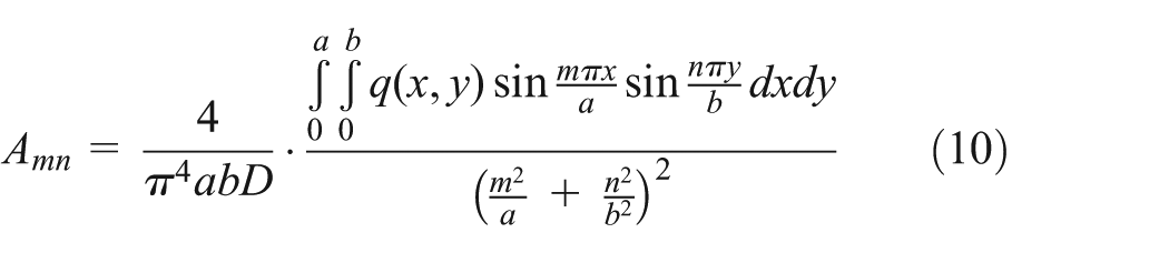
where
Obviously, the equation can satisfy the boundary conditions. 23 Substitute the formula into equation (7), then
So, the general solution of the flexural function of the four-sides simply supported sheet can be expressed as follows

The solution of equation (11) is also known as the Navier solution.
24
In the X–Y plane, as shown in Figure 2, assume that
Assume that
Thus, the interlayer gap at any points, before the two sheets completely contact each other, is as follows

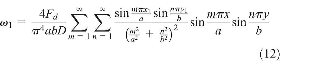
As can be seen from equations (12) and (13), the deflections of the upper and lower sheets at the same radius are different. But for upper or lower sheet, the deflections at the same circle are approximately equal. So, in this article, the average deflection of eight points located homogeneously at a circle of radius r is considered as the circle deflection.
Hence, when the drill thrust force acts at the lower sheet, the deflection at the circle of radius r is as follows

where k represents the eight points located homogeneously at the circle.
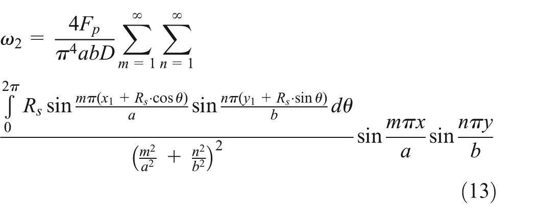
When the clamping force is applied on the upper sheet, the deflection at the circle of radius r is as follows
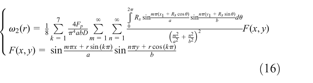
where k represents the eight points located homogeneously at the circle.
Then, by combining equations (15) and (16), the deflections caused by unit forces are as follows

In the investigation, the thickness of the sheet is
Material properties of different components.

The deflections of different radii under unit force (unit: 10−6 N/m).
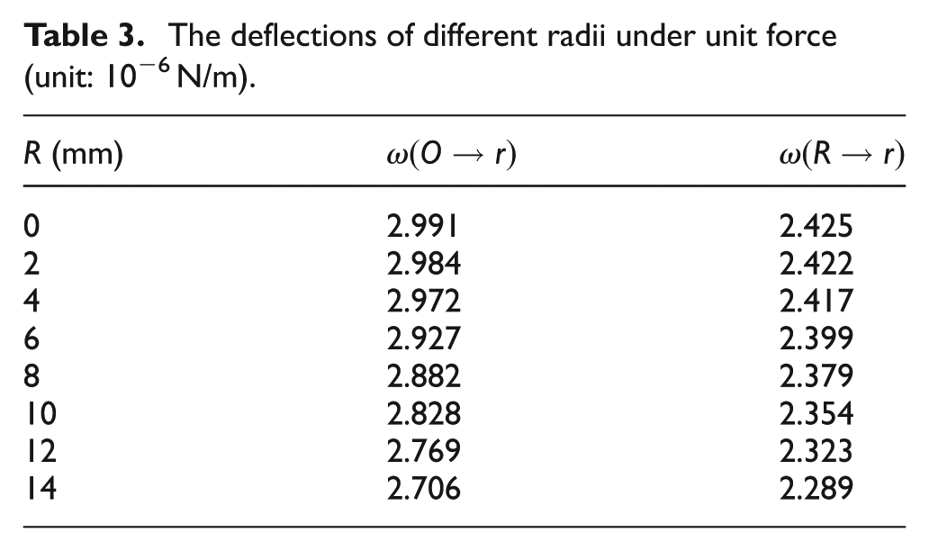
The deflection data presented in Table 3 further prove the deformation, and the interlayer gap at drilling center is the largest. Substitute these values into equation (6), and the curve of the clamping force,

The clamping force at different radii.
Stacked drilling simulation
FE modeling
When the drill reaches the sheets’ surface with the one-side clamping force, the deflection of the sheets increases gradually and the interlayer gap varies simultaneously. In order to verify theoretical analysis, a three-dimensional FE model is established using ABAQUS 6.13. The model is built based on the research of W Tian et al. 20
The model consists of two aluminum alloy sheets and one clamping foot. The material properties are displayed in Table 2. The dimensions of the sheets are 200 × 100 × 2 mm. The clamping foot is a metal ring with external diameter of 22.5 mm and inner diameter of 17.5 mm. The sheets are built as deformable bodies, while the clamping foot is defined as rigid body. The components are meshed by C3D8R. To achieve the desired analytical accuracy with computational efficiency, the mesh density in the drilling and clamping regions is denser than other areas. 26 The mesh condition is shown in Figure 5.

FE model mesh condition.
Multiple analytical steps with their specific conditions are sequentially introduced to the model. In initial step, the boundary conditions are set. The four sides of the sheets are constrained in Z-direction to make sure that the sheets are in the status of simply supporting. All freedoms of the clamping foot are restrained, except Z-direction. The initial interlayer gap is 0.4 mm. Contact properties are defined in step 1. The FE model includes contacts between clamping foot and upper sheet, and at the interface between the upper and lower sheets. A friction coefficient of 0.2 is specified for all of the contact surfaces. 20 The forces are loaded in step 2. The clamping force is applied on the clamping foot. The drilling force is loaded on the lower sheet through the hole of the upper sheet. Then, the deflections of the two sheets are calculated. The deflection of the each sheet is obtained from the average value of the eight points that locate homogeneously at the upper sheet exit or the lower sheet entrance. The interlayer gap is expressed as follows

where
Simulation results
During the simulation, the drilling thrust force is set as 130 N. The initial clamping force is 100 N. Then, the clamping force increases to 500 N gradually. The interlayer gap,

Total interlayer gap under different clamping forces.
The Von Mises stress is used to evaluate the stress status. 27 When the clamping force reaches 335 N, the stress status and displacement situations are illustrated in Figures 7 and 8, respectively. Obviously, the stress and strain are distributed symmetrically around the drilling center. Compared with other cases under different clamping forces, the stress and strain conditions are the best. Therefore, the optimal clamping force is 335 N. The difference between the theoretical optimal clamping force and the simulation result is approximately 2.9%. The results agree with the theoretical analysis.

Stress status of the stacked sheets.

Displacement status of the stacked sheets.
Experiments
Experimental details
The 2024-T3 aluminum alloy sheet of 200 × 100 × 2 mm is chosen as the specimen. The cemented carbide drill used is of cylindrical shank, 5.1 mm diameter, 120° point angle, and 15° helix angle. The KISTLER9257B dynamometer is utilized to measure the drilling thrust force and the clamping force. The Zeus Axio CSM 700 confocal microscope is applied to measure the burr conditions at the upper sheet exit and at the lower sheet entrance. The drilling test is conducted using the robotic automatic drilling system developed by Zhejiang University, as shown in Figure 9. 28 The system consists of KUKA KR360-2 industrial robot, robot mobile platform, drilling end effector, testing bench, and stacked aluminum sheet specimen.
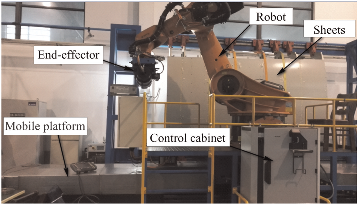
Automatic robotic drilling system.
The drilling process is illustrated in Figure 10. The specimens are fixed on the fixture. The spindle speed is 6000 r/min. The feed rate is 200 mm/min. 28 The clamping force (loaded through clamping foot) is controlled by the air cylinder installed on the end effector. The clamping force increases from 100 to 500 N step by step. Because of the control accuracy of the air cylinder, the increment of each step is 50 N. At each force level, three holes are drilled. 20
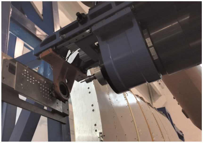
Local view of the drilling process.
Experiment results
The burr can be described by its burr cross section, as shown in Figure 11. 29 The burr heights measured under different clamping forces are exhibited in Tables 4 and 5 separately. The relationships of the average burr height and the clamping force are presented in Figure 12. Clearly, the burr heights drop significantly with the increment of the clamping force. When the clamping force is between 300 and 350 N, the slopes of both the curves turn small. Then, the fluctuations of both the curves are quite small when the clamping force is larger than 350 N. The burr heights tend to be stable at a value around 0.04 mm. It proves that the stacked sheets begin to contact to each other completely when the clamping force is larger than 300 N.

Cross section and measured parameters of a burr. 29
The burr height at the upper sheet exit.

The burr height at the lower sheet entrance.


The curves of burr height and the clamping force.
The burrs at upper sheet exit and lower sheet entrance under 50-fold microscope are presented in Figures 13 and 14, respectively. As can be seen, the burrs at the upper and lower sheets are obvious when the clamping force is relatively small. When the clamping force achieves 300 N, the burrs are not so apparent. The burrs disappear when the clamping force continually rise to 350 N. The hole surfaces and hole edges of both sheets are smooth. The phenomenon shows that the optimal clamping force is between 300 and 350 N. The conclusion is identical to the theoretical calculation and FE simulations.
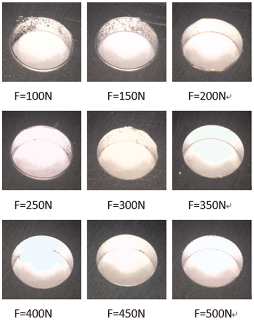
Burrs at upper sheet exit.

Burrs at lower sheet entrance.
Conclusion
In this study, a simple and clear relationship between the clamping force and the interlayer burr formation is presented. The smallest clamping force is considered as the optimal clamping force. Hence, the interlayer gap would be eliminated under the optimal clamping force. The shell theory is introduced to calculate the optimal clamping force. Numerical simulations and experimental verifications are conducted as well. The results further demonstrate the validity of the theoretical analysis.
Footnotes
Academic Editor: Xichun Luo
Declaration of conflicting interests
The author(s) declared no potential conflicts of interest with respect to the research, authorship, and/or publication of this article.
Funding
The author(s) disclosed receipt of the following financial support for the research, authorship, and/or publication of this article: The work described in this paper has been supported by grants from the Science Fund for Creative Research Groups of National Natural Science Foundation of China (no. 51521064) and special scientific research for civil aircraft (no. MJ-2015-G-081).