
Abstract
In this article, the nonlinear damping characteristics of magnetorheological damper are expressed with hyperbolic tangent model to simulate its mechanical experimental results. The fitted hyperbolic tangent model can represent hysteretic behavior for magnetorheological damper exactly. Based on the hyperbolic tangent model, a quarter-car model with magnetorheological damper is established, and a new hybrid fuzzy and fuzzy proportional-integral-derivative (HFFPID) controller integrated with hybrid fuzzy control and fuzzy proportional–integral–derivative control is developed to improve the semi-active suspension performance, which can overcome the absence of precise mathematical model. Furthermore, numerical simulations for fuzzy proportional–integral–derivative (PID), hybrid fuzzy proportional–integral–derivative (HFPID), and HFFPID controllers are investigated to demonstrate the effectiveness of the proposed approaches. The simulation results show that the body acceleration, suspension deflection, and tyre displacement can be reduced more effectively using HFFPID controller under sinusoidal road excitation. It can be further concluded that the suspension performance is improved more effectively by using HFFPID controller under random road excitation, especially in the peak points.
Keywords
Introduction
Suspension is one of the most important parts for vehicle, which directly affects the vehicle performance such as ride comfort and handling stability. To improve the damping effect of vehicle suspension, the traditional passive suspension, active suspension, and semi-active suspension appeared in succession.1–5 Traditional passive suspension is composed of elastic elements and damping elements with fixed parameters, which has been widely used in vehicle suspension since it requires no external energy input and simple structure. However, it is only an optimal compromise scheme with poor adaptabilities to the varied driving conditions and arbitrary road excitations. 6 Active suspension can obtain a high-quality vibration isolation system to achieve the ideal control for vehicle through a controllable actuator, which has great potential in improving the suspension performance. However, its development and application are constrained due to its large energy consumption, high cost, and complex structure. 7 Semi-active suspension can accommodate to various roads and driving conditions to improve ride comfort and handling stability by changing the damping characteristics of the shock absorber, which is close to active suspension in the vibration attenuation effect. It has attracted more attention in numerous scholars and manufacturers because of its advantages including high energy efficiency and low cost. 8
Magnetorheological (MR) damper is an intelligent device extensively applied in semi-active suspension systems to damp the undesired vibrations. There is a magnetic field generated by applying a direct current to the coil in MR damper, which makes MR fluids changing from the viscous liquid state to the semi-solid state in the resistance gap, thereby a controllable damping force can be obtained. MR damper has many distinct advantages such as simple structure, small size, low energy consumption, fast response, large dynamic range, and continuously controllable resistance. 9 However, the damping characteristics of MR damper exhibit strong nonlinear hysteretic characteristics. Therefore, it is one of the key tasks to establish a more accurate mechanical model of MR damper for the design of semi-active suspension system. To describe the dynamic damping characteristics accurately, many experts proposed different kinds of mechanical models for MR damper, which can be divided into non-parametric and parametric models. Among these, non-parametric models mainly include polynomial model, neural network model, and adaptive neuro fuzzy model.10–12 These models can trace the dynamic behavior for MR damper without considering the general physical characteristics of implemented parameters. However, parametric models need a physical modeling process, which is composed of certain mechanical elements including dashpot, spring, and friction. Parametric models applied in the semi-active control system mainly include Bingham model, Phenomenological model, Bouc–Wen model, hyperbolic tangent model, and Dahl model.13–17 In recent study, the hyperbolic tangent model is selected to fit the experimental results of MR damper. This selected model can also be effectively used for designing inverse model for MR damper.
Another key task is to design the corresponding control algorithm for semi-active suspension system. An appropriate control algorithm can make semi-active suspension to achieve the same vibration attenuation effect as active suspension. However, heavy nonlinear behaviors and modeling uncertainties complicate the development of high-performance controllers.18,19 To improve the dynamics of nonlinear and uncertain suspension systems, many advanced nonlinear control strategies have been investigated, such as, Piotr Krauze et al. investigated the effectiveness of FxLMS algorithm in a quarter-car model including the Bouc–Wen model of MR damper. It was stated that the FxLMS-based algorithm efficiently mitigated vibrations in the range of both the low and high frequencies compared with the classical skyhook algorithm. 20 Weichao Sun et al. addressed the problem of H∞ control for active vehicle suspension systems in finite frequency domain. By the Generalized Kalman–Yakubovich–Popov lemma, the ride comfort has been improved by minimizing the H∞ norm in specific frequency band. 21 H Du et al. 22 presented a direct voltage control method based on Takagi–Sugeno fuzzy algorithm for MR damper. The simulation results showed that a continuous control signal can be obtained and fast control response is guaranteed. Balamurugan et al. 23 proposed a generalized MR damper model and verified it in vehicle suspension system using skyhook sliding mode control algorithm. Recently, Devdutt Singh et al. integrated a hybrid fuzzy proportional–integral–derivative (HFPID) controller with coupled rules controller in combination with MR damper in primary suspension system of traveling semi-active quarter-car system, and polynomial model was selected for simulation purpose of experimental results of MR damper. Simulation responses showed that the proposed controller provided best performance. 24 At present, many control strategies have been developed and evaluated for their practical applicability in semi-active suspension system, which includes Linear–Quadratic–Gaussian (LQG) control, adaptive neuro fuzzy control, skyhook on-off control, sliding mode control, adaptive robust control, and integrated adaptive robust control.25–35
HFPID controller is composed of fuzzy controller and traditional proportional–integral–derivative (PID) controller, 24 which integrates their advantages. However, it is difficult to get the precise parameters of traditional PID controller in the HFPID controller. Thus, the control accuracy is not ensured. To obtain optimal performance with strong robustness, a new HFFPID controller integrated with hybrid fuzzy control and fuzzy-PID control is developed on the basis of HFPID controller, which can automatically realize the optimal tuning of PID parameters based on fuzzy inference. Consequently, its adaptive robustness is stronger.
The main objective of this work is related to vibration control of MR semi-active suspension system with different controllers. First, the mechanical experimental results of MR damper are modeled using hyperbolic tangent model. Then, a quarter-car model with MR damper is established. To further validate the effectiveness of the proposed HFFPID controller, simulation results of semi-active suspension system based on hyperbolic tangent model controlled by the HFFPID controller, HFPID controller, fuzzy-PID controller, and passive suspension under sinusoidal road excitation and random road excitation are compared and analyzed considering the body acceleration, suspension deflection, and tyre displacement as the evaluation indices of the vibration attenuation effect.
Hyperbolic tangent model of MR damper
The MR damper presented in this article is manufactured by our research group, which belongs to shear-valve mode damper with single piston rod. Figure 1 shows the mechanical performance test system for the proposed MR damper, and the prototyping of MR damper is shown in Figure 2. The test system mainly consists of INSTRON tensile machine, WYK-301 type DC regulated power supply, control monitor, and the proposed MR damper. The upper end of MR damper is fixed on the upper beam of test bench, which remains motionless. Meanwhile, the lower end of MR damper is excited by simulated vibration. The control monitor is used to display and save experimental data of the damping force. Here, MR damper works in a 1 Hz sinusoid excitation with amplitude of 10 mm, and the supplied current to MR damper varied from minimum 0 A to maximum 1 A with the step of 0.25 A. The test results of force–displacement and force–velocity of MR damper are shown in Figure 3.
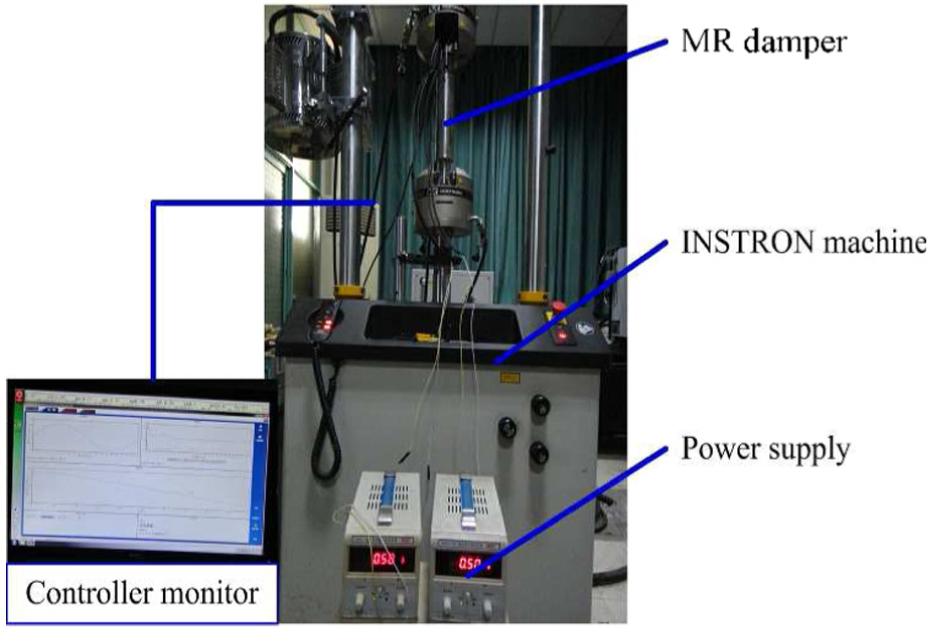
Test system of mechanical performance.
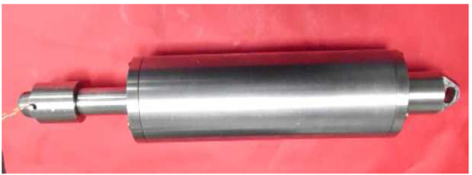
Prototyping of MR damper.

Damping performances of proposed MR damper: (a) force–displacement and (b) force–velocity.
The Bingham model has a clear physical meaning with simple expression, and only three parameters need to be determined by experimental data, but its precision is relatively low. Phenomenological model can reflect the nonlinear hysteretic characteristics of MR damper perfectly, 14 but more parameters need to be identified, which is extremely sophisticated. Hyperbolic tangent model presented by Kwok et al. 36 consists of the viscous damping (dashpot) placed in parallel with spring stiffness and a hysteretic component. The model is given by

where x and
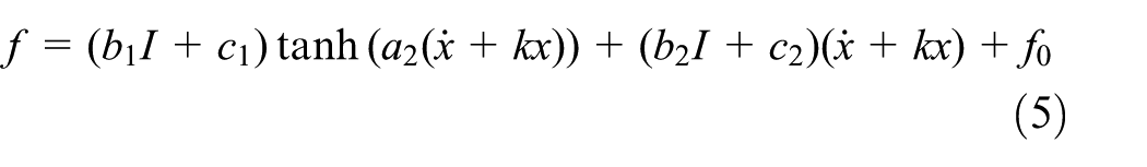
Note that the model contains only a simple hyperbolic tangent function, so it can be computed efficiently by parameter identifications, as well as included and implemented in controller design. Therefore, hyperbolic tangent model is used to represent the hysteretic behavior of the MR damper. However, the model contains a sign function and six parameters needed to be identified. Furthermore, it is improved to reduce complexity in the model. The identified parameters are reduced to five, and the governing equation for this improved model is given as

where a1 is a scale factor of the hysteresis, which is related to the control current; a2 and a3 are the parameters related to the viscous damping coefficient in the pre-yield region to post-yield region, respectively; and k = V0/X0 (V0 and X0 are defined as the absolute value of critical piston velocity and critical piston displacement when the damping force f is zero, respectively), which is a scale factor of hysteresis loop width.
It appears that the maximum damping force of MR damper increases gradually with the increasing control current as shown in Figure 3. The coefficients in equation (2) under the different current are obtained through parameter identification solved by least-square method based on the above experimental results of MR damper. The principle of identification is to acquire the unknown five coefficients to minimize equation (3), that is, to minimize the error sum of squares between the predicted force and the measured force
Parameter identification results are given in Table 1. Observing Table 1, the coefficients associated with current in equation (2) can be distinguished by studying the relationship between the same coefficients and current under the different currents.
Parameter identification results.

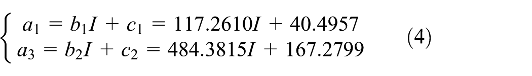
Table 1 shows that the parameters a2, k, and f0 are not changed significantly under the different current, which can be considered as a constant value, and their mean value a2 = 776.5809, k = 0.3506, and f0 = 7.1671 are selected. Parameters a1 and a3 increase along with the increasing current, which have an evident linear relationship. The relationship between these two variables and current is shown in Figure 4.

Relationship between ai, i = 1, 3, and current: (a) parameter a1 and (b) parameter a3.
The relationship between parameters a1 and a3, and current are obtained by linear regression approach, and it is expressed as
Therefore, hyperbolic tangent model is given by
A comparison between the predicted responses for hyperbolic tangent model and experimental results under different currents are provided in Figure 5. It can be concluded that the improved hyperbolic tangent model matches very closely with the experimental results, which can be effectively applied to semi-active control. Moreover, the desired damping force supplied by controller as well as the piston displacement and velocity can be known easily.
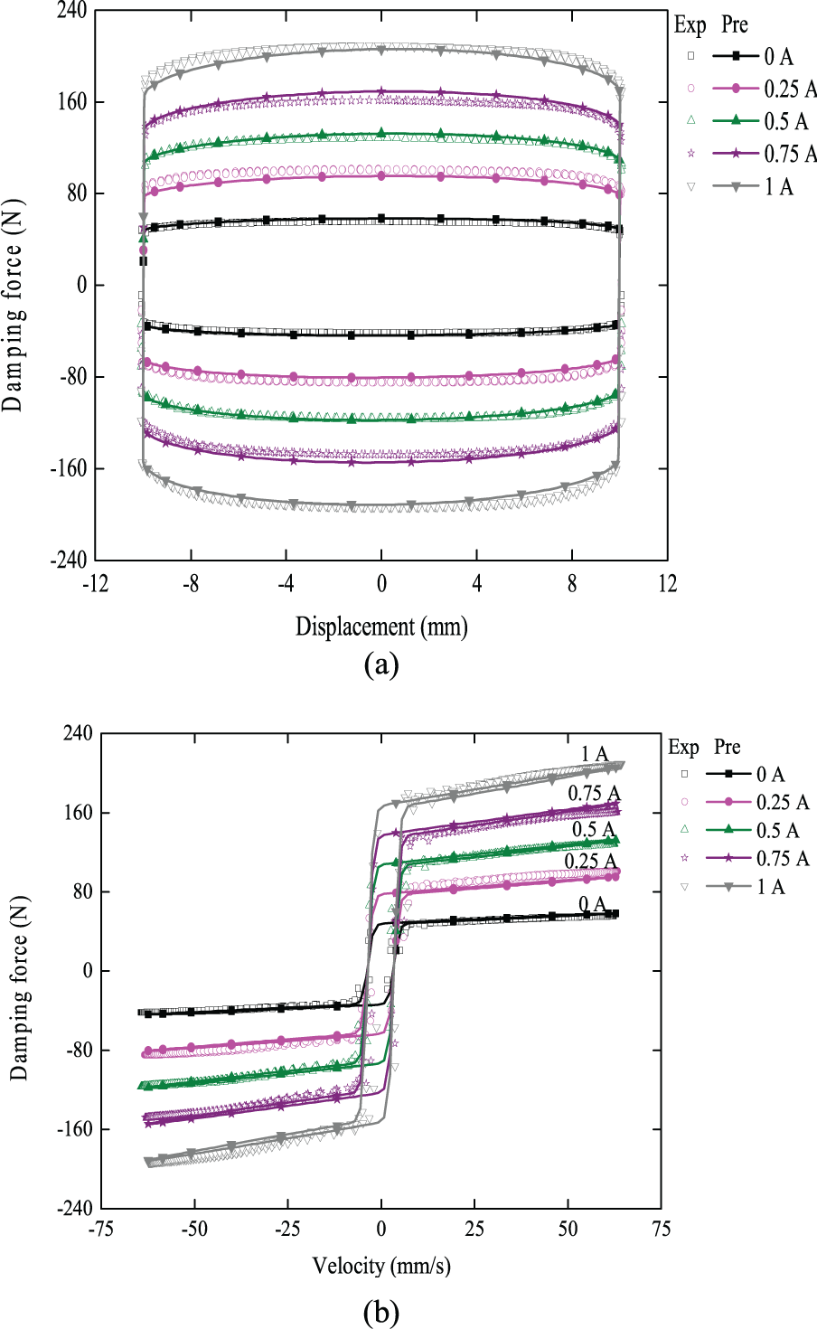
Comparison of predicted and experimental results: (a) force–displacement and (b) force–velocity.
Quarter-car suspension model
In this section, a quarter-car suspension model with MR damper is taken for comparative study, as shown in Figure 6.

Quarter-car suspension model with MR damper.
This model is selected to investigate vertical dynamics of the complete structure with neglecting other motions such as vehicle roll and pitch dynamics. The governing equations of motion for the sprung mass and unsprung mass are

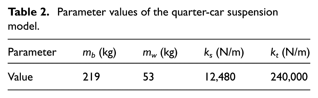
where mb is the sprung mass, which represents the car body; mw is the unsprung mass, which represents the wheel assembly; zb and zw are the displacements of the sprung mass and unsprung mass, respectively; zr is the road displacement input; ks and kt are the suspension stiffness and tyre stiffness, respectively; and f represents the damping control force generated by MR damper. The parameter values of the quarter-car suspension model are listed in Table 2.
Parameter values of the quarter-car suspension model.
Taking dynamic relationship into account, the road displacement zr and damping control force f are selected as the input vectors, and the state variables can be defined as

Accordingly, a state-space equation for equation (6) is derived as

where

Semi-active control algorithm
Semi-active controller design
First, the fuzzy controller does not require the accurate mathematical model for the controlled object, and it can achieve the effective nonlinear control effect according to the implemented operator’s experience and knowledge, which has been frequently tested in various active and semi-active suspensions for vibration control.37,38 Second, the fuzzy-PID controller was often used in vehicle suspension vibration control due to its strong adaptability and robust performance. 39 The HFFPID controller combines the advantages of both fuzzy controller and fuzzy-PID controller in a single hybrid-type controller.
Fuzzy controller
Fuzzy controller has two input and one output variables. One of the input variables chosen for the fuzzy controller is the error (e) between the car body velocity and its reference value, and the change rate of the error (de) denoted by the error between the car body acceleration and its reference value is selected as another input variable. The desired damping force (u) is selected as the output variable. The seven linguistic variables that are selected to describe the input and output variables are as follows: NB (negative big), NM (negative medium), NS (negative small), ZE (zero), PS (positive small), PM (positive medium), and PB (positive big). In this article, triangular membership functions (MFs) are used for linguistic variables. Thus, the concerned MFs for the input and output variables are shown in Figure 7. Variables are all defined in the interval [−1, 1]. Actual intervals of variables are decided by the following scaling factors: kv, ka, and ku, respectively. Fuzzy controller scheme is shown in Figure 8.

MFs of the input and output variables.
Fuzzy controller scheme.
According to the fuzzy rules of the rule base look-up table: if e is Ei and de is Ej, then u is U(i,j), the corresponding fuzzy control rule base is presented in Table 3. For instance, one of the possible rules is that if e is NS and de is PB, then u is PM. This rule can be explained as follows: if the error is small, the car body velocity is around the reference value. Meanwhile, a positive big value of change rate of the error shows that the car body velocity rapidly approaches to the reference value, but the car body acceleration is partial large. Consequently, the controller output should be a positive medium value to prevent overshoot and make a brake effect. Moreover, Mamdani method is selected as the fuzzy inference method, and the centroid method is used for defuzzification, which converts the linguistic variables to numerical data.
Rule base for fuzzy controller.

NB: negative big; NM: negative medium; NS: negative small, ZE: zero; PS: positive small; PM: positive medium; PB: positive big.
Fuzzy-PID controller
In the conventional PID controller, the ideal characteristics of the proportion, integration, and differentiation can be expressed as

where Kp is the proportional gain; Ki is the integral gain; Kd is the differential gain; e(t) represents the controller input, which is the error between the car body velocity and its reference value; and u(t) represents the controller output, which is the desired damping force.
Fuzzy-PID controller is a composite controller which connects with fuzzy control and conventional PID control, as shown in Figure 9. It can automatically modify the three parameters online for PID controller according to the fuzzy control theory to meet the different requirements, which merges the advantages of fuzzy controller and PID controller including flexibility, robustness, simplicity, and reliability. So, this strategy improves the dynamic response of the system with high dynamic and static performance. 40 Observing Figure 9, the specific working process of the fuzzy-PID controller can be explained as follows: first, the output variables ΔKp, ΔKi, and ΔKd are obtained by fuzzy controller with e and de as the input variables through fuzzy inference. Subsequently, they are all output to the PID controller so that the PID parameters are tuned dynamically in real time. Finally, the PID control parameters Kp, Ki, and Kd are received. It can be represented as

where Kp, Ki, and Kd are the final parameters of fuzzy-PID controller; Kp0, Ki0, and Kd0 are the initial parameters of PID controller; ΔKp, ΔKi, and ΔKd are the output variables of fuzzy controller; and qp, qi, and qd are the corresponding correction coefficient.

Fuzzy-PID controller scheme.
The above seven linguistic variables are used to describe the input variables in this fuzzy controller, and the MFs are also shown in Figure 7. The output variables are all portrayed by four linguistic variables: ZE (zero), S (small), M (medium), and B (big), as shown in Figure 10. The output variables are all defined in interval [0, 1]. According to the rule base look-up table, if e is Ei and de is Ej, then u is U(i,j), the corresponding fuzzy control rule bases are presented in Tables 4–6, separately. Equally, Mamdani method is selected as the fuzzy inference method, and the centroid method is used for defuzzification in this fuzzy controller.

MFs of the output variables.
Rule base for variable ΔKp.
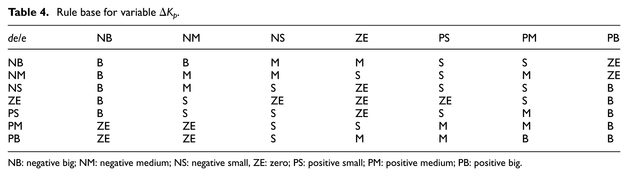
NB: negative big; NM: negative medium; NS: negative small, ZE: zero; PS: positive small; PM: positive medium; PB: positive big.
Rule base for variable ΔKi.

NB: negative big; NM: negative medium; NS: negative small, ZE: zero; PS: positive small; PM: positive medium; PB: positive big.
Rule base for variable ΔKd.

NB: negative big; NM: negative medium; NS: negative small, ZE: zero; PS: positive small; PM: positive medium; PB: positive big.
HFFPID controller
An intelligent switching mechanism is added for HFFPID controller. Conventional PID controller in HFPID controller is replaced by fuzzy-PID controller with stronger adaptive robustness in HFFPID controller. It can be automatically switched between fuzzy controller and fuzzy-PID controller according to whether the error is larger than the threshold. Its detailed principle can be described as follows

where w is the switching threshold value.
The fuzzy controller is chosen as the output of the control system when the car body velocity is larger than the switching threshold value. In this case, fuzzy controller has better robustness. Otherwise, if the car body velocity is smaller than the switching threshold value, the control system transfers immediately the controller from fuzzy controller to fuzzy-PID controller. In the car body velocity near the reference value, the fuzzy-PID controller has better accuracy and effectiveness. Thus, the designed HFFPID controller takes full advantage of both the fuzzy controller and fuzzy-PID controller.
Semi-active control constraint
The damping force generated by MR damper under the same piston velocity and displacement is a bounded value because the current inputs into the MR damper coil is between the minimum current and the maximum current. Accordingly, it is necessary to saturate the desired damping control force obtained by the semi-active controller. The constrained damping control force is expressed as

where fmin(t) is the minimum damping force at a certain piston velocity; fmax(t) is the maximum damping force at a certain piston velocity; and flim(t) is the constrained control damping force. The maximum input current of MR damper is 1 A, and the minimum damping force and the maximum damping force can be calculated at a certain piston velocity and displacement according to formula (5), respectively.
It can be seen from Figure 5(b) that the damping force provided by MR damper is basically located in the first and third quadrants in the force–velocity curve. Hence, MR damper can output the damping force to track the desired control force when the symbol of the desired control force is the same as that of the piston velocity. However, MR damper can hardly track the desired control force when the desired control force and piston velocity are opposite sign, and the input current is set to 0 A under this circumstances. The final traceable damping control force can be obtained as

where ftra(t) represents the traceable damping control force; fe(t) represents the desired control force; and v(t) is the piston velocity.
According to formulas (5), (12), and (13), the corresponding control current in the hyperbolic tangent inverse model is

where m = tanh(a2(
Numerical simulation analysis
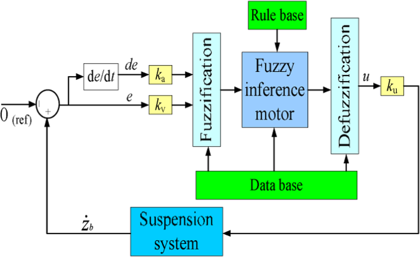
To validate the effectiveness of the designed HFFPID controller and evaluate various suspension performance, two types of road excitations are considered in the simulation. Considering the car body acceleration, suspension deflection, and tyre displacement as the evaluation indices of the vibration attenuation effect, simulation of semi-active suspension is conducted by the hyperbolic tangent model. Comparisons among different controllers, containing the HFFPID controller, HFPID controller, fuzzy-PID controller, and passive suspension (i.e. input control current is 0 A) are analyzed. The parameter values of the quarter-car suspension model are listed in Table 2. Control schematic for semi-active suspension system is shown in Figure 11.

Control schematic for semi-active suspension system.
A sinusoidal road input is adopted as the first road excitation with amplitude of 0.07 m and a frequency of 1 Hz. The body acceleration Ab, suspension deflection Ds, and tyre displacement Dt under sinusoidal road excitation are shown in Figures 12–14, respectively. It can be seen that the better vibration reduction performance are obtained for the controlled semi-active suspensions compared to the uncontrolled passive suspension, and HFFPID controller has the best vibration attenuation performance compared with other controllers in semi-active suspensions. In semi-active suspension control, the comparison between the actual damping control force generated by MR damper and the desired control force generated by controllers is provided in Figure 15, and the input control current for MR damper under different controllers is provided in Figure 16. It is also observed that the desired control force is relatively smooth, whereas the mutation phenomenon appears in the actual damping control force and input control current. The reason for this is that the input control current is suddenly loaded when the desired control force is satisfied from the non-constrained state to constrained state. But it can also be concluded from Figure 15 that both of them show the extremely similar variation trend, which means that the hyperbolic tangent model of MR damper can precisely track the desired control force so that the semi-active suspension performance is almost equal to the active one. According to equation (14), the input control current controlled by fuzzy-PID controller is relatively small because its suspension deflection and relative velocity are relatively large. Conversely, the input control current controlled by HFFPID controller is relatively large because its suspension deflection and relative velocity are smaller than other controllers.

Body acceleration under sinusoidal road excitation.

Suspension deflection under sinusoidal road excitation.
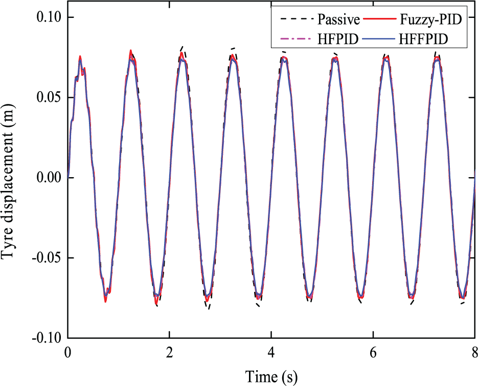
Tyre displacement under sinusoidal road excitation.

Comparison of the actual damping force and the desired control force under sinusoidal road excitation: (a) fuzzy-PID, (b) HFPID, and (c) HFFPID.

Input control current under sinusoidal road excitation: (a) fuzzy-PID, (b) HFPID, and (c) HFFPID.
Compared with passive suspension, the reduction percentage of root mean square (RMS) value of the body acceleration, suspension deflection, and tyre displacement under sinusoidal road excitation for fuzzy-PID controller, HFPID controller, and HFFPID controller is shown in Figure 17. The body acceleration controlled by HFFPID controller, HFPID controller, and fuzzy-PID controller is reduced by 58.9%, 42.1%, and 37.3% compared with the passive suspension, respectively, and their suspension deflection are reduced by 58.7%, 40.2%, and 42.2%, respectively. Their tyre displacements are reduced by 22.7%, 17.8%, and 7.8%, respectively. It can be concluded that the body acceleration, suspension deflection, and tyre displacement can be reduced more effectively by HFFPID controller compared with passive suspension and other controllers, which results in a better vibration attenuation effect. In addition, the body acceleration and tyre displacement controlled by HFPID controller are smaller than fuzzy-PID controller, while the suspension deflection performance controlled by fuzzy-PID controller is better than HFPID controller.
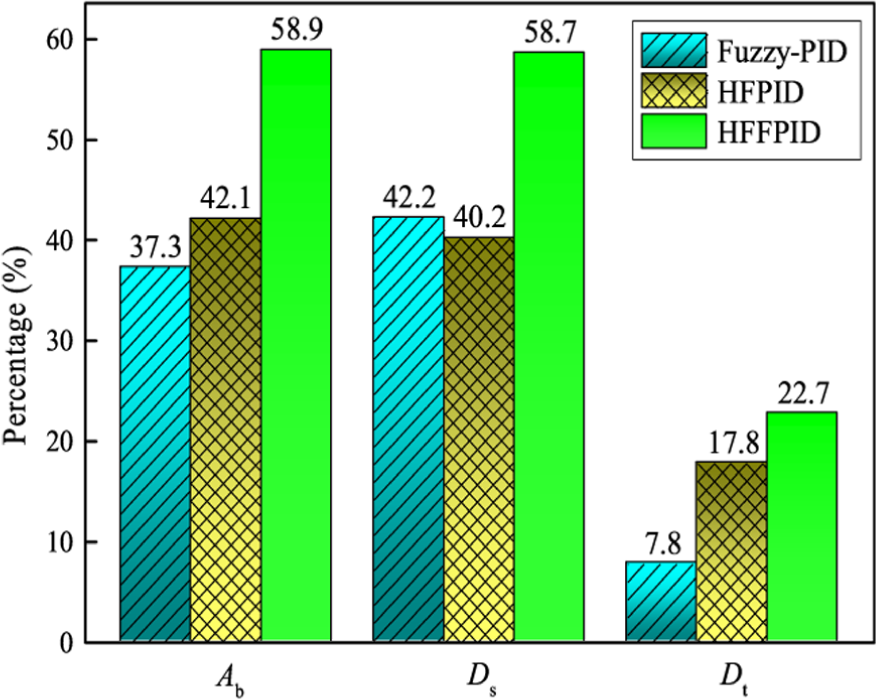
Reduction percentage of RMS under sinusoidal road excitation.
To further validate the effectiveness of the designed HFFPID controller, a second type of road excitation, that is, a random road excitation, is applied. 41 The road displacement of the random road excitation is generated by

where zr(t) is the road displacement; α and δ are the undetermined coefficients; Gq(n0) is the road irregularity coefficient; w0(t) is the white noise with covariance of 1; and v is the vehicle speed.
In the simulation, α = 0.111 m−1, δ = 4.44 m, Gq(n0) = 1024 × 10−6 m3 in D grade road, and v = 20 m/s. The body acceleration and suspension deflection under random road excitation are presented in Figures 18 and 19, respectively. Further analysis reveals that the proposed HFFPID controller is effective to improve suspension performance. Meanwhile, the comparison between the actual damping control force and desired control force is provided in Figure 20, and the input control current for MR damper is provided in Figure 21. The simulation results for this case prove the validity of the hyperbolic tangent inverse model again.

Body acceleration under random road excitation.

Suspension deflection under random road excitation.

Comparison of the actual damping force and the desired control force under random road excitation: (a) fuzzy-PID, (b) HFPID, and (c) HFFPID.

Input control current under random road excitation: (a) fuzzy-PID, (b) HFPID, and (c) HFFPID.
Under random road excitation, the reduction percentage of the RMS value of the body acceleration and suspension deflection compared with passive suspension is presented in Figure 22, respectively, for fuzzy-PID controller, HFPID controller, and HFFPID controller. Figure 22 shows that the body acceleration controlled by HFFPID controller, HFPID controller, and fuzzy-PID controller are decreased, respectively, by 55.9%, 42.6%, and 37.9% compared with the passive suspension, and their suspension deflection is decreased, respectively, by 49.8%, 22.5%, and 17.5%. It can be inferred that the body acceleration and suspension deflection controlled by HFFPID controller are less than other controllers, especially in the peak points. Moreover, the body acceleration and suspension deflection controlled by HFFPID controller still maintain a similar reduction percentage compared with that in sinusoidal road excitation, whereas the reduction percentage of the suspension deflection controlled by fuzzy-PID controller and HFFPID controller are decreased remarkably compared with that in sinusoidal road excitation. The results show that HFFPID controller has better robustness, which can provide the advanced suspension performance and improve ride comfort in general.
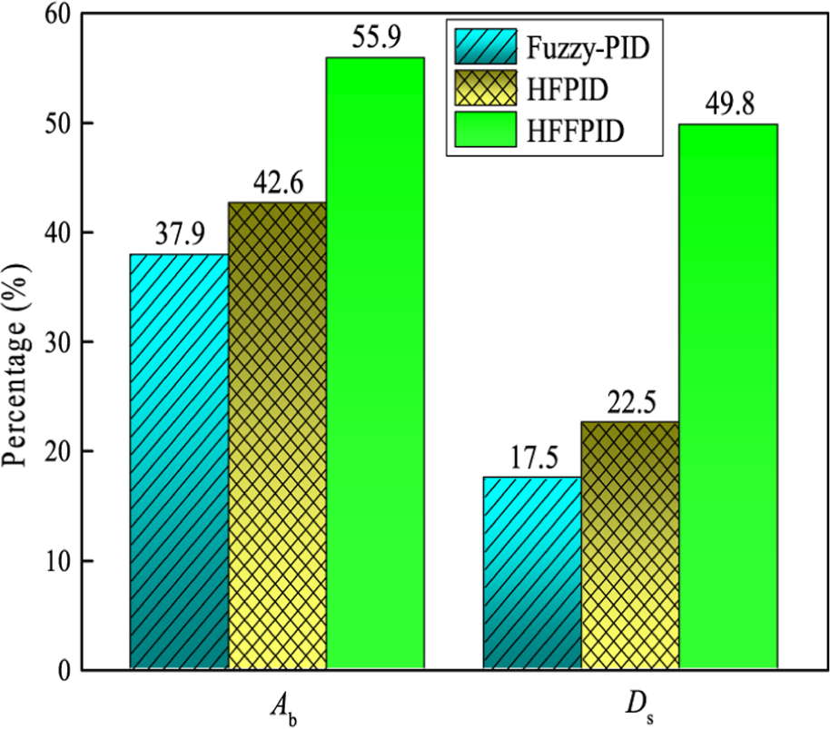
Reduction percentage of RMS under random road excitation.
Conclusion
In the semi-active suspension control system using MR damper, the vibration attenuation effect depends on not only the control algorithm of the system but also the accurate mechanical model of MR damper. In this article, the mechanical experimental results of MR damper are fitted using hyperbolic tangent model, and a quarter-car model with MR damper is also established. At the same time, a novel HFFPID controller integrated with fuzzy-PID control and fuzzy control is developed. Furthermore, considering the body acceleration, suspension deflection, and tyre displacement as the evaluation indices of the vibration attenuation effect, the control performances using the proposed hybrid controller are simulated compared with HFPID controller, fuzzy-PID controller, and passive suspension.
Under sinusoidal road excitation, the results show that the body acceleration of semi-active suspension controlled by HFFPID, HFPID, and fuzzy-PID controller is reduced by 58.9%, 42.1%, and 37.3%, respectively, compared with the passive suspension, and their suspension deflection are reduced by 58.7%, 40.2%, and 42.2%, respectively, and their tyre displacements are reduced by 22.7%, 17.8%, and 7.8%, respectively. The tyre displacement reduction is not obvious due to the contradiction between the ride comfort and handling stability control. Simultaneously, the actual output damping force has a similar varied trend with the expected control force in the semi-active suspension control. Thus, the hyperbolic tangent model of MR damper can track the expected control force.
Under random road excitation, the body acceleration of semi-active suspension controlled by HFFPID, HFPID, and fuzzy-PID controller are decreased by 55.9%, 42.6%, and 37.9%, respectively, compared with the passive suspension, and their suspension deflection are decreased by 49.8%, 22.5%, and 17.5%, respectively. It can be further seen that the HFFPID controller improves more effectively the vibration reduction performance of suspension than other controllers, especially at peak points, which gives better ride comfort.
Footnotes
Academic Editor: Zheng Chen
Declaration of conflicting interests
The author(s) declared no potential conflicts of interest with respect to the research, authorship, and/or publication of this article.
Funding
The author(s) disclosed receipt of the following financial support for the research, authorship, and/or publication of this article: This research was financially supported by the National Natural Science Foundation of China (nos 51475165 and 11462004), the Natural Science Foundation of Jiangxi Province of China (no. 20151BAB206035), Jiangxi Provincial Foundation for Leaders of Academic and Disciplines in Science (no. 20162BCB22019), and the Educational Commission Project of Jiangxi Province of China (no. GJJ150525).