
Abstract
We present an element-free Galerkin method for electromechanical coupled fracture analysis in piezoelectric materials. Singularity terms were introduced into the approximation function of the new method to describe the displacement and electric fields near the crack. The new method requires a smaller domain to describe the crack-tip singular field compared with the finite element method. Then, we computed the J-integrals of piezoelectric materials and investigated the effects of crack length on the computational precision. Numerical examples were used to highlight the accuracy of the new method compared with the analytical solutions and finite element method.
Keywords
Introduction
Piezoelectric materials are a type of functional materials with the piezoelectric effect that converts between electrical and mechanical energies. There are direct and inverse piezoelectric effects. The former, discovered first in quartz crystals by P. Curie and J. Curie in 1880, refers to the appearance of an electric field in a piezoelectric solid under mechanical loading. The second effect refers to the mechanical deformation of piezoelectric solids under the presence of an electric field. The existence of this mechanical behavior was predicted by G. Lippmann in 1881 using energy conservation and electric current conservation and experimentally verified by the Curie brothers a few months later. The discovery of the piezoelectric effect aroused strong interest from the scientific community. So far, abundant achievements have been made in the microscopic and macroscopic theories of piezoelectric devices and their applications in modern science and technology.1–5
At present, the most widely used piezoelectric materials are piezoelectric ceramics and piezoelectric ceramic–polymer composites. Piezoelectric ceramics are typical brittle materials with low fracture toughness and high defect sensitivity. Thus, the concentration of stress fields and electric fields caused by defects (e.g. cracks, inclusions, and pores) which occurs during manufacture or service often makes these devices dysfunctional and even causes breakdown or fracture damage under electromechanical joint effects. This characteristic restricts further improvement in the performance of related devices and wider application of piezoelectric ceramics. Therefore, in the fields of solid-state mechanics and materials physics, it is urgent to further understand the physiomechanical mechanisms of fractures of piezoelectric materials, to make reliable analysis and prediction, and to uncover the underlying toughening mechanisms.
For >10 years, researchers in the fields of mechanics, physics, and material science had extensively studied the fracture performances of piezoelectric materials by means of theoretical analysis, numerical calculation, and experimental observation and achieved remarkable results. The theoretical framework about the fracture mechanics of piezoelectric materials has been preliminarily established.6–13
In the field of engineering technology, analytic methods have provided accurate solutions only to problems with relatively simple equations and regular geometry. No analytic solutions can be obtained for most problems, especially in the case of complex engineering. Therefore, years of efforts have been devoted to develop another approach—the numerical method. The rapid development and wide application of computers in recent years have led to the presence of three major research approaches, including numerical analysis, theoretical investigation, and experimental investigation. As one of the most effective tools for mechanics study, the finite element and other numerical methods are widely used in scientific research and engineering practice. For instance, finite element method (FEM) was used to analyze piezoelectric structures with cracks under dynamic electromechanical loading. 14 Numerical algorithms for fracture analysis in piezoelectric structures were used with FEM to determine fracture parameters. 15 Extended FEM was applied to analyze fractures in piezoelectric materials. 16 Partition of unity methods for fractures allows for arbitrary crack growth without remeshing. These methods have been successfully extended to brittle fracture modeling.17–19
Compared to FEM, however, element-free method is unique in solving the problems of fracture growth, plastic flow, geometric distortion, phase transition, and singularity of materials. Noticeably, in establishing the discrete equation, this method does not need element division but only has to arrange discrete points in the global domain. Thus, it avoids the complicated mesh formation and greatly reduces the impact of mesh distortion.
The moving least-squares (MLS) approximation 20 is an important method to construct the shape function in element-free method. The shape function that is formed with the MLS approximation can obtain a very precise solution. One disadvantage of the MLS approximation is that the final algebra equation system is sometimes ill-conditioned. Thus, sometimes, we cannot obtain a good solution or even correctly obtain a numerical solution with the MLS approximation. Then, improved moving least-squares (IMLS) approximation was discussed by Cheng and colleagues.21–23 The complex variable moving least-squares (CVMLS) approximation, which is an approximation of a vector function, has been developed and presented. 24 To enhance its computational efficiency, improved complex variable moving least-squares (ICVMLS) approximation was studied. 25 Various meshless methods have been applied to analyze smart materials and structures such as the element-free Galerkin method (EFGM), 26 the meshless point collocation method, 27 point interpolation meshless method 28 and radial point interpolation method,29,30 a novel truly hybrid meshless-differential-order reduction method, 31 and local Petrov–Galerkin method. 32 Among these methods, the EFGM33–35 is featured with high compatibility, high stability, no shear lock of volume even in use of linear primary function, fast convergence, and high accuracy. And the improved EFGM based on the IMLS approximation was investigated by Zhang et al. 36 Combining CVMLS approximation with the EFGM, the complex variable element-free Galerkin (CVEFG) method for elasto-plasticity problems was presented. 37 Based on the EFGM and the ICVMLS approximation, the improved complex variable element-free Galerkin (ICVEFG) method for two-dimensional (2D) potential problems was presented. 38 EFGM is widely used in fracture mechanics analysis.39–42 A meshless method was developed for discontinuous mechanical problems.43–48
In this study, we first introduced the piezoelectric constitutive equations, the MLS approximation, and the formulation of electromechanical coupled EFGM. Then, equivalent-domain J-integral for piezoelectric materials was presented, and numerical examples were used to demonstrate the accuracy and efficiency of the EFGM.
Piezoelectric constitutive equations
The electroelastic response of a piezoelectric body of volume Ω and regular boundary surface S is governed by the mechanical and electrostatic equilibrium equations


where
The basic equations for piezoelectric materials include balance laws and constitutive relations. The constitutive relations, usually called piezoelectric equations in the theory of piezoelectricity, describe the interaction effect among stress, electric displacement, and electric field as follows


where
Strains are related to displacements as follows


where
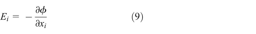
The electric field is related to the electric potential as follows
Essential boundary conditions

Natural boundary conditions

where
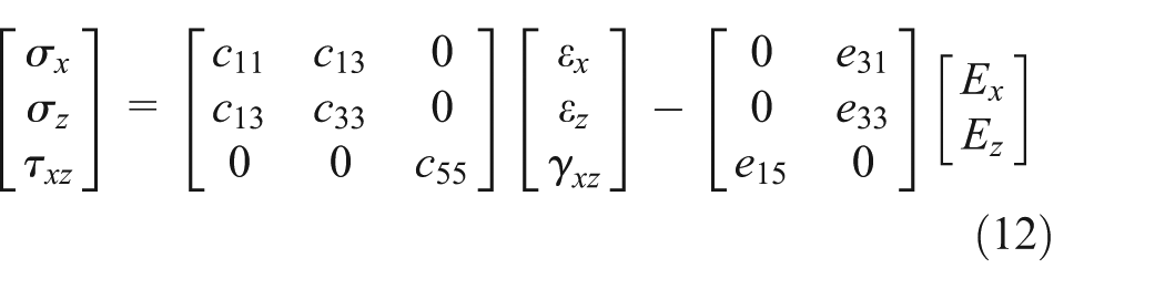
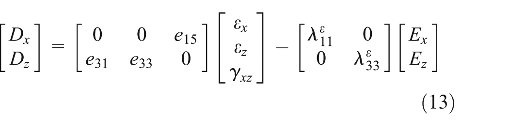
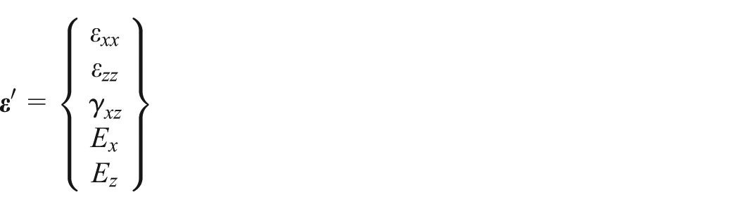
The 2D matrix forms of mechanical and electrical constitutive equations for piezoelectric materials are
By substituting equations (5)–(9) into equations (12) and (13), we can recast equations (3) and (4) using mechanical displacement and electric potential. For a 2D piezoelectric problem, the equation governing electrical equilibrium is

and the equations governing mechanical equilibrium are


MLS approximation
We consider function

where


and the quadratic basis functions are


For piezoelectric problems, it is advisable to use the regular enriched basis functions stemming from the isotropic elasticity. It should be mentioned that similar results have been obtained independently using alternative regular enriched basis functions for cracks in confined plasticity problems. 49 The regular enriched basis functions incorporate the radial and angular behaviors of the 2D asymptotic crack-tip displacement field

where r and θ are polar coordinates with the crack tip as the origin.
where
Moreover


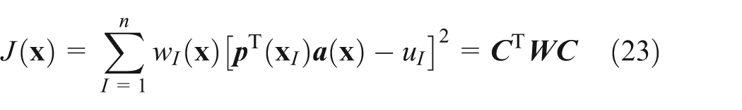
The stationarity of

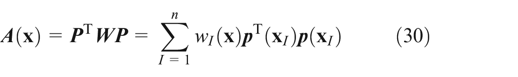
which results in the following equation system

where


Then,

The EFGM for electromechanical coupled problems
Displacement

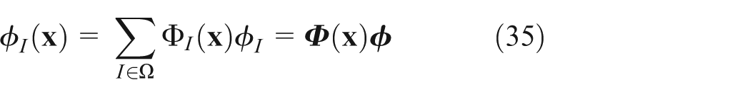
where Ω is the support domain and Φ(


The potential energy in the domain Ω is expressed as follows

where


are the generalized volume force vector, the given generalized boundary force vector, the generalized boundary displacement vector, and the generalized penalty function coefficient vector, respectively. Due to the great difference between mechanical field and electric field coefficient matrices, the two penalty functions must be selected separately.
and

are the generalized strain matrix and generalized elastic matrix, respectively.
When the system reaches equilibrium, its potential energy is minimized. Using the variation principle in equation (38) leads to the following equilibrium equation

where
In this work, a weight function based on Gaussian distribution is used
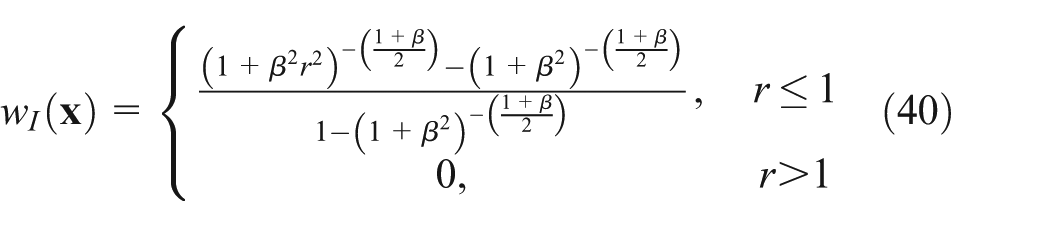
where

where scale is a scaling parameter and
To avoid any fracture-caused discontinuity in the shape functions, we used a diffraction method to modify

where

Diffraction method.
Equivalent-domain J-integral for piezoelectric materials
The J-integral defined in Rice 50 is one parameter of the nonlinear fracture problem and also a path-independent integral (Figure 2)
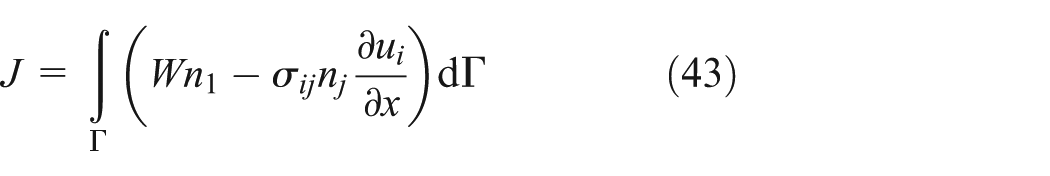
where
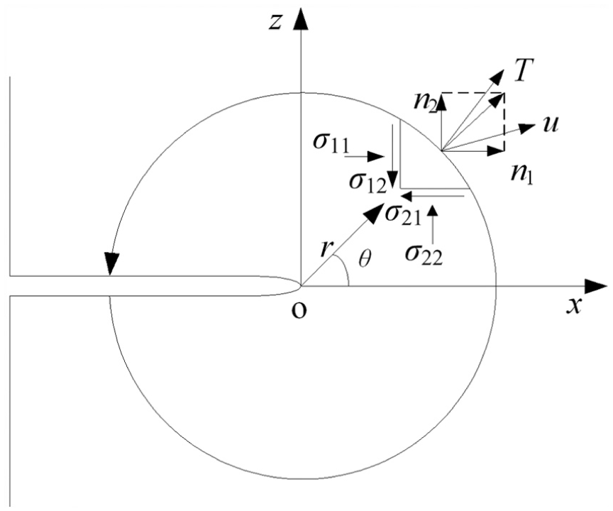
J-integral path around a crack tip.
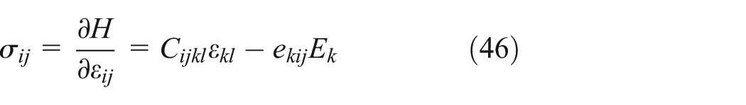
The J-integral for piezoelectric materials was deduced as follows 51

where H is the electric enthalpy

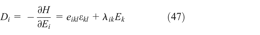
Note that the crack is considered as impermeable and traction free. Numerical determination of the J-integral is very difficult because the contour, surface, and volume integrals in the grids should be defined precisely. The closed integration path is transformed to an equivalent-domain integral (EDI) by applying Gauss’ integral theorem (Figure 3). According to the rule of path independence, equation (44) could be rewritten as

where S = Γ + Γ+ + Γ− − Γ ε , ni is an outward normal vector, and q is a weighting function that must be continuous and meet the following condition

Equivalent-domain J-integral.
Numerical examples
Infinite PZT-4 square plate with a central crack
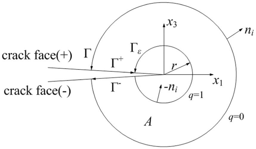
The centrally cracked infinite PZT-4 plate (height 2h = 40 m, width 2w = 40 m, and crack length 2a = 2 m) is shown in Figure 4. The plate width which is 20 times of crack length can be considered as large enough for simulation of an infinite cracked plate. As shown in Figure 4, the positive x3 direction is defined as the polarization direction,
Piezoelectric plate with central crack.
The material properties of PZT-4 are as follows: c11 = 13.9 × 10¹⁰ N/m, c12 = 7.78 × 10¹⁰ N/m, c13 = 7.43 × 10¹⁰ N/m, c33 = 11.3 × 10¹⁰ N/m, c44 = 2.56 ×10¹⁰ N/m, e31 = −6.98 C/m2, e33 = 13.84 C/m2, e15 = 13.44 C/m2, ε11 = 6.00 × 10⁻⁹ C/V m, and ε33 = 5.47 × 10⁻⁹ C/V m.
Due to the symmetry of the plate, only half of the plate needs to be modeled. In this process, 41 × 81 nodes were uniformly distributed in the computational domain, and here, we used 40 × 80 background grids. In each grid, an 8 × 8 Gaussian integral was adopted.
To improve the precision, we added four nodes at the crack tip and added the number of nodes with the background grid coordinates at the crack (Figure 5).

Additional nodes around the crack.
For different combinations of stress and electric field intensity, we computed the J-integral (EDI) with the integral area as shown in Figure 6. The results are listed in Table 1. The largest difference is only 0.12% compared with the real energy release rate that had been determined for a centrally cracked infinite PZT-4 plate. When the numbers of nodes were approximately equal and the crack-tip elements of FEM were locally refined, EFGM was still more precise than FEM (Table 1). Figure 7 shows the finite element mesh by FEM, which includes 1424 elements


Equivalent-domain J-integral.
J-integrals for centrally cracked infinite PZT-4 plate (N/m).
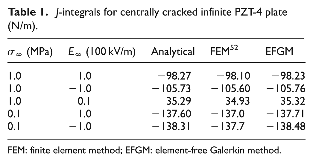
FEM: finite element method; EFGM: element-free Galerkin method.

Finite element mesh for the quadrant of the piezoelectric plate.
Infinite PZT-5H square plate with a central crack
The material of the plate in this section is PZT-5H, where the other conditions are the same as in section “Infinite PZT-4 square plate with a central crack.” The plate size, mechanics, electric load, and boundary conditions are shown in Figure 4.
The material properties of PZT-5H are as follows: c11 = 12.6 × 10¹⁰ N/m, c12 = 5 × 10¹⁰ N/m, c13 = 8.41 × 10¹⁰ N/m, c33 = 11.7 × 10¹⁰ N/m, c44 = 2.30 ×10¹⁰ N/m, e31 = −6.50 C/m2, e33 = 23.3 C/m2, e15 = 17.44 C/m2, ε11 = 150.3 × 10⁻¹⁰ C/V m, and ε33 = 130 × 10−10 C/V m.
The analytical solution of J-integral in this plate was calculated as follows

The J-integral results obtained by EFGM are more accurate compared with those determined by FEM (Table 2).
J-integrals for centrally cracked infinite PZT-5H plate (N/m).
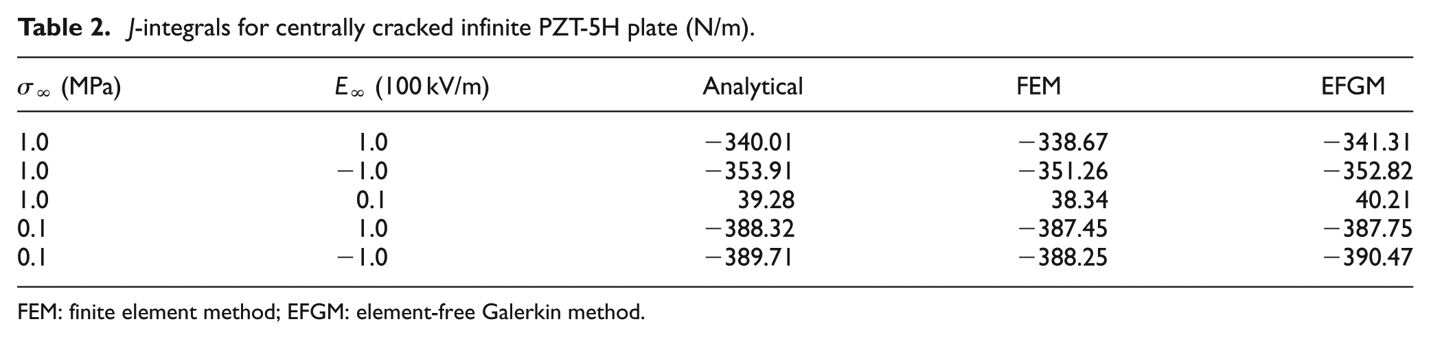
FEM: finite element method; EFGM: element-free Galerkin method.
Infinite PZT-5H square plate with central cracks of different lengths
The PZT-5H square plate is 20 m high (2h) and 20 m wide (2w) with the crack length (2a) of 0.5, 0.75, 1, 1.25, and 1.5 m (Figure 4). The J-integral was calculated for each crack. The computational domain involved 81 × 161 uniformly distributed nodes, of which 80 × 160 background grids were used. In each grid, a 4 × 4 gauss Gaussian integral was adopted.
The J-integral calculations for different crack lengths and different scales are shown in Figure 8. The results show that the errors at scale = 1.3 are large due to the small radius of the supporting zone. At scale = 1.7, 2.3, and 3.0, the EFGM calculated results agree well with the analytical solutions no matter how the crack length changes. Moreover, as the size of the influence domain increases, the accuracy of the results is improved but changes very little in general, which indicates that the method has high stability.
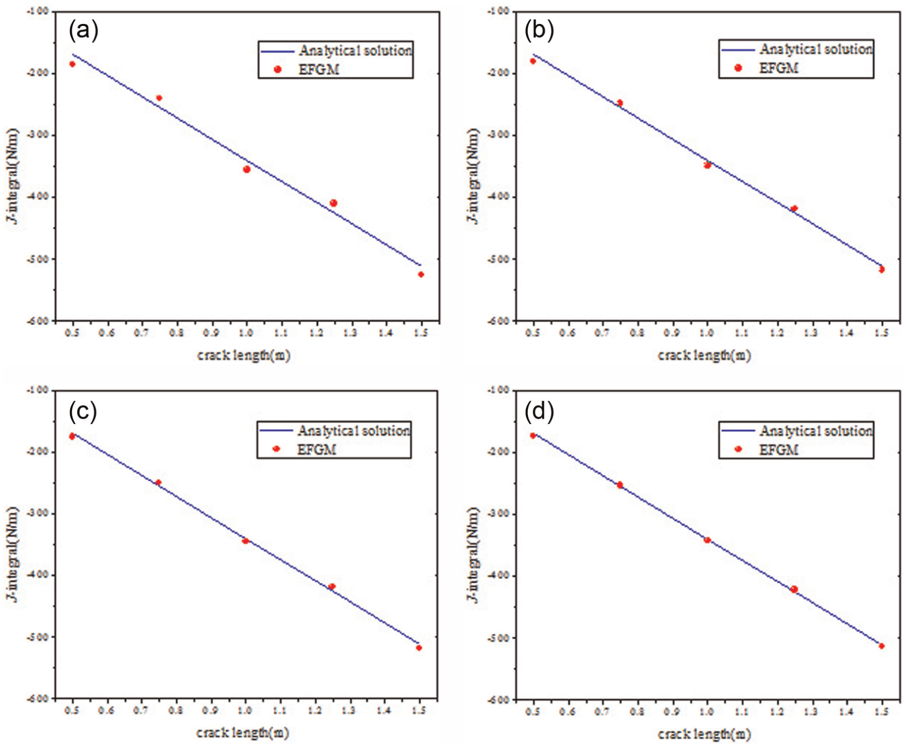
J-integral of different crack lengths at (a) scale = 1.3, (b) scale = 1.7, (c) scale = 2.3, and (d) scale = 3.0.
A rectangular plate with central inclined crack
Here, a finite rectangular PZT-4 plate with a central crack inclined by 45° to the horizontal direction is considered (Figure 9). Other parameters are as follows: uniform tension σ = 1 GPa and electric displacement D = 1 C/m2 in the y-direction; the ratio of crack length to width a/h = 0.1 (h = l m, a = 0.1 m).

A rectangular plate with a central and inclined crack.
The high accuracy of EFGM is observed in Table 3. The comparison of relative errors shows that the EFGM results are more accurate than the FEM results.
Error comparison between two methods of the mechanical and electrical intensity factors for a rectangular plate with an inclined crack under coupled σ = 1 GPa and D = 1 C/m2.

FEM: finite element method; EFGM: element-free Galerkin method.
Electromechanical kinked crack
In this example, a kinked crack problem is analyzed. The intensity factors of a kinked crack in the infinite plate under electrical far-field load D = 1 C/m2 are calculated and compared with the analytical solution and FEM results. The piezoelectric material is PZT-4. The kinked crack model is shown in Figure 10. A straight main crack of the length a continues into a straight crack branch of the length c = 0.25a, deviating from the main crack by the angle α = 30°. The poling axis of the piezoelectric material is oriented perpendicular to the main crack. The KII corresponding analytical results are not given in Xu and Rajapakse. 53

Kinked crack in PZT-4.
Table 4 lists the corresponding field intensity factors, analytical results, and FEM results. The comparison of relative errors demonstrates that the EFGM results are more accurate than the FEM results.
The mechanical and electrical intensity factors at branch tip in PZT-4.
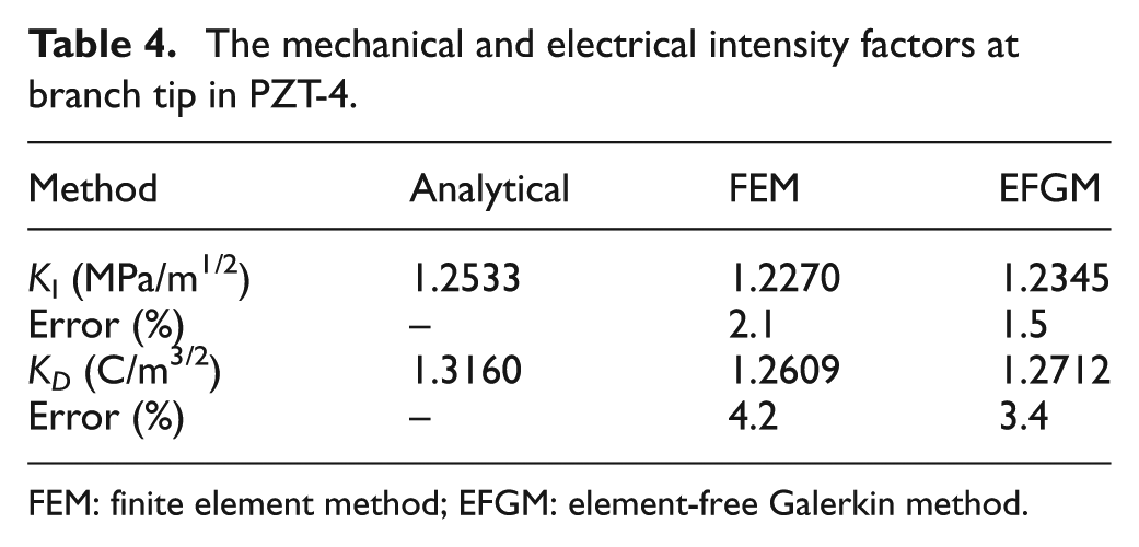
FEM: finite element method; EFGM: element-free Galerkin method.
Conclusion
The wide application of piezoelectric structures into innovative technical areas has highlighted the problems of strength and reliability, which have to be carefully investigated. Sophisticated analysis of electromechanical properties of cracks is needed to quantitatively assess fracture and fatigue. The fracture mechanics approach for crack-like defects in piezoelectric materials reveals the electromechanical coupled field singularities. Effective numerical methods are needed to evaluate fracture behavior of cracks in arbitrary piezoelectric structures under combined electromechanical loading.
In this article, the EFGM was proposed for electromechanical crack analyses, and its accuracy was verified by four examples. The conclusions from numerical simulation are listed in the following:
Singularity terms which could describe the displacement and electric fields near the crack were introduced to the approximation function of the EFGM.
The new method is unique that it only uses a small domain to describe the crack-tip singular field.
A series of numerical examples for infinite square plate with cracks of piezoelectric materials were solved, and the J-integrals were calculated. EFGM is more precise than FEM. With the increase in crack length, the calculations of J-integrals agree well with the analytical solutions. EFGM can be an alternative numerical method for analysis of electromechanical coupling problems. It may be potentially extended to dynamic fracture analysis of piezoelectric materials.
Footnotes
Academic Editor: Mohammad Talha
Declaration of conflicting interests
The author(s) declared no potential conflicts of interest with respect to the research, authorship, and/or publication of this article.
Funding
The author(s) disclosed receipt of the following financial support for the research, authorship, and/or publication of this article: This work was financially supported by National Natural Science Foundation of China (grant no. 51305157) and Technology Development Plan of Jilin Province (grant nos 20160520064JH and 20170101043JC).