
Abstract
Considering the complexity structure of wind turbines, it is difficult to establish an accurate model for wind turbines. This article proposed an improved model based on the vibration signal analysis to investigate the onshore wind turbine dynamic behavior. The model is formulated using the Euler–Lagrangian approach in which the dynamic interaction effects between the nacelle and the tower and the effects between the tower and the foundation are considered. The nacelle is assumed as a mass with 2 degrees of freedom at the top of a flexible tower. And the tower is considered as a beam with elastic end support. The foundation stiffness can influence the dynamic response of wind turbines due to the soft soils surrounding the tower base. A rotational spring and a lateral spring derived from the foundation are used to reflect the interaction between the tower and the foundation. Finally, a comparison with existing National Renewable Energy Laboratory 5-MW baseline wind turbine model is performed. And a field experiment has been implemented to validate the model. The vibration signal of the nacelle and the tower is analyzed to determine the model parameters. Results show that the proposed model is accurate and practical for dynamic property analysis of wind turbine.
Introduction
Wind energy is one of the fastest growing renewable energies, according to the collected statistical data by the Global Wind Energy Council (GWEC), the global total installations wind power capacity was 369.6 GW at the end of 2014. 1 Along with it, the reliability issues have been emerging. Vibration characteristics of wind turbines may essentially influence the stability, performance, and lifetime of wind turbine systems. There are many studies that have been devoted to improve the availability and survivability of wind turbines.2–4 Recently, condition monitoring and fault detection systems have been proved an effective way to ensure that the wind turbine works more efficient, more robust, and less costly. 5 However, the dynamic characteristic of wind turbine is also an important issue in wind turbine design, operation, and maintenance but is rarely considered for a condition monitoring system or a fault diagnosis system.
Much attention has been paid to the dynamic analysis of wind turbine.6–8 Dynamic analysis for wind turbines includes experimental modal analysis and theoretical modal analysis. The theoretical modal analysis can be applied more easily and widely. The main challenge in analyzing the dynamic properties of wind turbines with the theoretical model is estimating the parameters of the model. For experimental analysis, it considers the dynamic properties of a kinetic system by measuring and analyzing the input and response signal. 9 But there are limits to implement experimental test for large-scale wind turbines because of the inaccessibility and complicated construction of wind turbine. As vibration analysis is widely used in wind turbine condition monitoring and fault diagnosis system, the vibration signals of some components of the wind turbine can be obtained by the condition monitoring system and developed to improve the dynamic analysis of the wind turbine.
It is difficult to model the entire wind turbine in detail, but the structure of the wind turbine can be simplified as several key subsystems. Many subsystems may contribute to the vibration of the wind turbine, such as the flapping of blades, the rotation of the shaft and driven chain, and the oscillation of the tower. A comprehensive aeroelastic powerful simulator capable of predicting both the extreme and fatigue loads of two- and three-bladed horizontal-axis wind turbines (HAWTs), named fatigue, aerodynamics, structures, and turbulence (FAST), was developed by National Renewable Energy Laboratory (NREL).10,11 The modules of FAST (AeroDyn, HydroDyn, etc.) rely on different physical domains of the coupled aero-hydro-servo-elastic solution. Therefore, FAST requires detailed parameters of the wind turbine, including aerodynamic shape, material properties, control strategies, and so on. However, these parameters are not always available, which will limit the use of FAST.
The blade characteristics in the low-order vibration conditions were investigated by Ye et al. 9 Murtagh et al.12,13 investigated the dynamic interaction between the rotor blades and the tower and developed an analytical model for passive control of wind turbine vibrations. A hybrid multibody system method was proposed for wind turbine structure analysis, which could capture all the rigid and elastic mechanical components, couplings, and important motions based on nonlinear kinetics. 14 Kessentini et al. 15 used a mathematical model with flexible tower and blades to estimate the effects of the vibrations of the tower and blades. They found that the effects of the pitch angle and the blade orientation on the natural frequencies and the mode shapes of the wind turbine can be considered insignificant factors, while small vibrations of the tower may induce severe blade deflections. Staino and Basu 16 also developed a multi-modal mathematical model describing the dynamics of flexible rotor blades and their interaction with the turbine tower, taking the variable rotor speed into account. However, the above works ignored the foundation factor due to different soil types. Nevertheless, the soil–structure interaction (SSI) is also essential for the dynamic properties of wind turbine. The effect of foundation has been considered for the free vibration analysis of wind turbines in Adhikari and Bhattacharya 17 and Harte et al. 18 For the purpose of wind turbine condition monitoring, Liu 19 established a blade–cabin–tower coupling system to analyze the vibration and force in wind turbines. Recently, Liu performed a numerical vibration analysis by further considering the wind turbine system as a blade–cabin–tower coupling system. However, the model parameters are difficult to discern, and the essential property of the wind turbine such as the natural frequency is not included in the mentioned papers. For this reason, appropriate modeling of the relevant dynamics is necessary for reliable wind turbine vibration analysis applications.
In this article, a dynamic model of the vibrations for a three-bladed HAWT is formulated according to the Euler–Lagrangian 20 approach. The model contains the effect of foundation and nacelle system and the effect of interaction of foundation and tower. Moreover, blade flapping influence is considered as a part of the external force effect, and the mass of the blades is lumped with the mass of the nacelle. At first, a mathematical model for a HAWT structure is characterized by a set of ordinary differential equations and four partial differential equations with the boundary conditions. Then, the vibration analysis and an experiment are performed to validate the proposed model, and the effects of a variety of model parameters are discussed. The result shows that the proposed model is able to represent the dynamic properties of the wind turbine. The approach may be used in preliminary quantitative design and building a condition monitoring system with the dynamic behaviors of the wind turbine.
Modeling the nacelle–tower–foundation system
A typical HAWT is shown in Figure 1, which includes several components such as blades, gearbox, generator, nacelle, tower, and foundation. We develop a mathematical model for an HAWT consisted of a flexible tower, a mechanical idealization flexible foundation, a rigid blade–rotor–gearbox–generator (BRGG) system with a translational nacelle, as shown in Figure 2. The multi-degree of freedom (DOF) superstructure model is formulated using the Euler–Lagrangian equations, 21 as follows

where

The main structure of a horizontal-axis wind turbine.
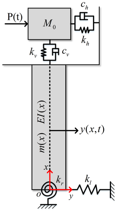
Wind turbine model.
The model is developed for the vibration analysis of the system on the top of tower. Here, we consider the effect of the vibration of blades as a part of the outside force
The lumped mass of BRGG is modeled as a 2-DOF system which could be represented by

The wind turbine vibration model is, therefore, described by

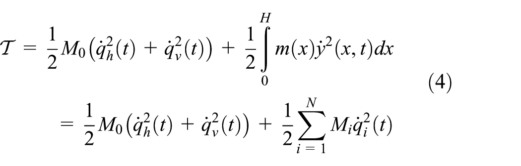
The total kinetic energy of the model can be written as
The total potential energy of the system is given by

where the terms


where E is Young’s modulus of elasticity of the tower material,
The dissipation function of the system is given by
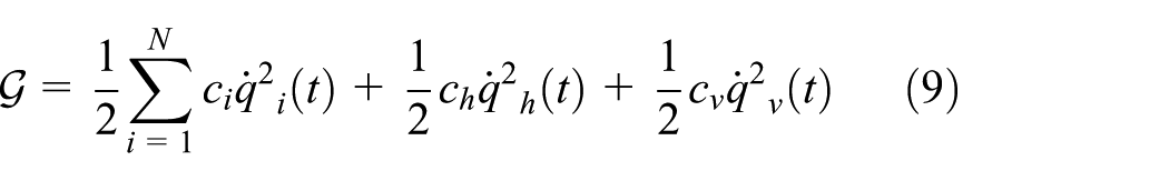
where
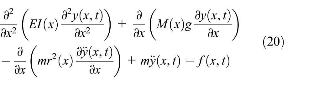
According to equation (1), the equations of motion for the wind turbine vibration model with N + 2 DOFs can be written as

where
The mass matrix
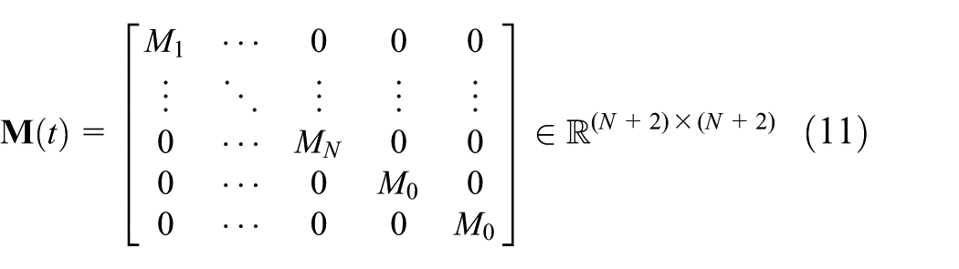
where

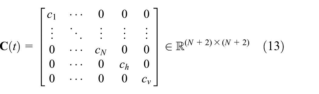
The damping matrix
The stiffness matrix
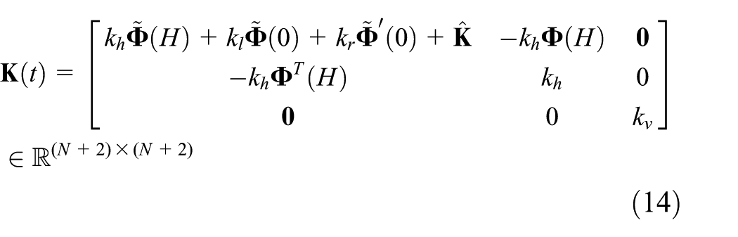
where

assuming orthogonal modes of vibration implies

the Hadamard multiplication defined as
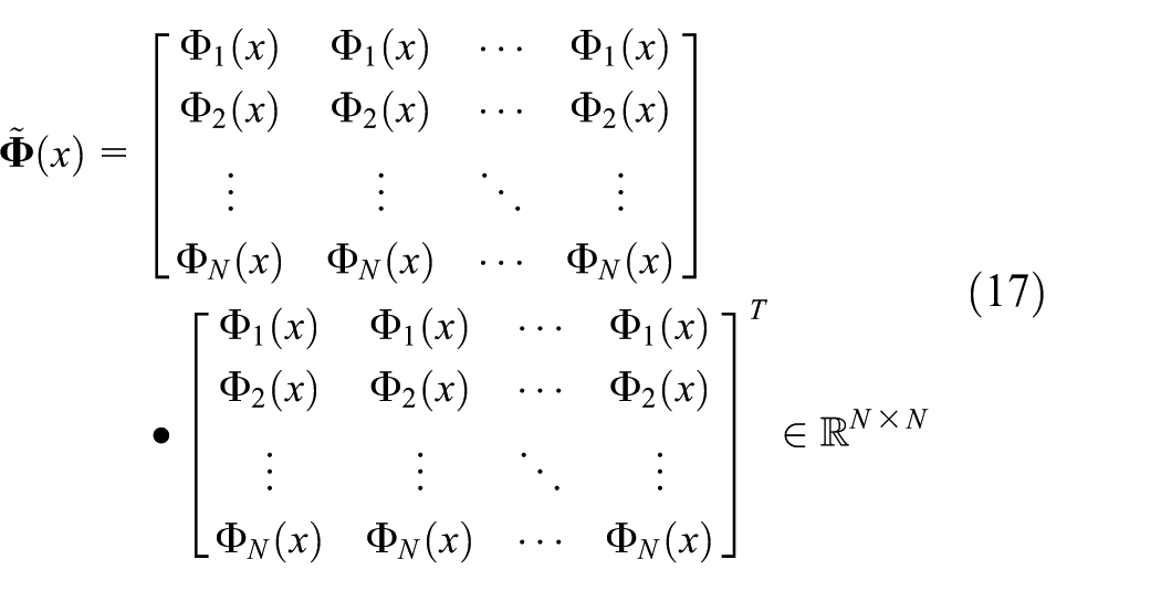
where
According to the formulation derived in this article, the tower–foundation interaction and the nacelle–tower interaction can be illustrated by numerical analysis.
Natural frequency of the wind turbine system can be obtained from the free vibration status by considering the outside force of the system is zero. Therefore, we obtain the differential equation of motion of the system

The equation of motion of the beam can be given by 23
where
The model including only the fundamental mode of vibration captures the essential dynamics of the system. However, the exact closed-form solution is impossible to be obtained due to the complex nature of the resulting equations. For simplicity, here, we assume constant equivalent properties. Assuming that the properties are not changing with x, the tower can be simplified as an Euler–Bernoulli beam. As an Euler–Bernoulli beam, the shear transform and inertia can be without consideration
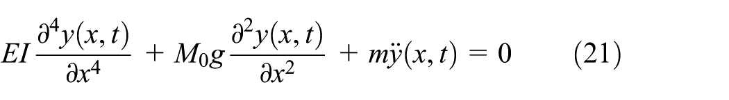
Assuming harmonic solution, we have

Then, normalizing the variable x, equation (22) can be written as

Substituting this in the equation of motion

Solving equation (24), we have

Assuming
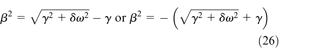
Therefore, the four roots of

where
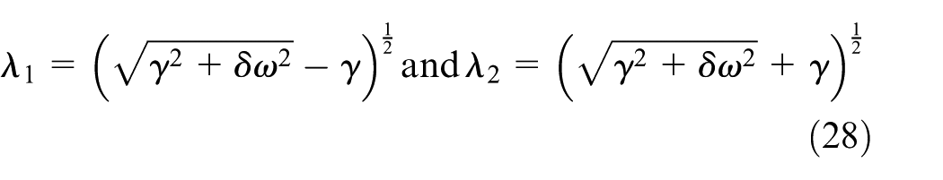
Such that a solution of equation (22) can be given as

with

which can be rewritten as

where
There are four boundary conditions associated with the tower, the bending moment
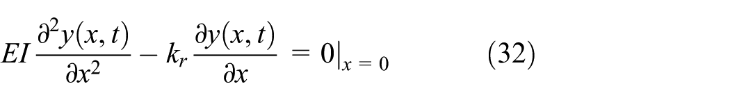

And the bending moment
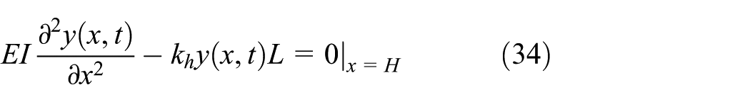

where L is the distance between the nacelle center and the tower top.
Substituting equation (29) in the four boundary conditions, equations (32)–(35) result in
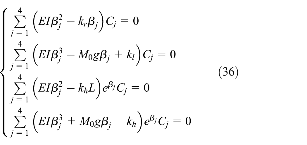
Arranging equation (36) with a matrix format

where


Considering the constant vector

This transcendental equation can be solved numerically. For the purpose of illustration, a numerical analysis and an experimental test have been compared for demonstrating the performance of the proposed model for the system.
Numerical simulation and analysis
In this article, the parameters are obtained from a 1.5-MW wind turbine YDF-1500-77. The wind turbine is a horizontal-axis upwind type, mainly consists of a three-bladed rotor which has an electric pitch-regulation, gearbox, yaw system, doubly fed induction generator (DFIG), and a partially rated converter. The wind turbine parameters used in the numerical example and field test are provided in Table 1.
Wind turbine parameters.

The second moment of area of tower can be obtained as

The mass density per unit length of the tower can be obtained as

The top mass of wind turbine can be obtained as

The distance between the nacelle center and the tower top can be obtained as

In general, at the fixed support, the values of the foundation stiffness parameters

As a result, how these stiffness parameters affect the overall behavior of the system will be analyzed, and the determination values of them will be derived from the test experiment in the next section.
The proposed model has been implemented in MATLAB with the numerical solution. In order to illustrate the effects of the variable parameters in the proposed model, different values of foundation lateral stiffness

The first natural frequency of the wind turbine with respect to the foundation lateral stiffness
In Figure 3, the first natural frequency of the wind turbine is enlarged with the increasing values of the stiffness parameters. The increasing stiffness will enhance the stability of the wind turbine and get higher values of the natural frequency as the fact. The parameter

The first natural frequency of nacelle in the axial direction under various vertical stiffnesses kv which range from 104 N/m to 107 N/m (with reference frequency f0 = 5.4 Hz when kv = 1.58 MN/m).
To validate the proposed model, we use the FAST10,11 model as a reference. The parameters used in the FAST numerical simulation must match those specified parameters in Table 1. We build the wind turbine model (YDF-1500-77) in this article by modifying the baseline wind turbine WindPACT 1.5 MW in FAST. The natural frequencies are calculated by performing an eigenanalysis on the first-order state matrix created from the linearization analysis. The natural frequency of tower fore-aft is 0.6642 Hz, and the tower side to side is 0.6557 Hz. The results show that the agreement among the proposed model, FAST, and the experiment are quite good.
In addition, specifications of the NREL offshore 5-MW baseline wind turbine
24
have been considered for validation of the proposed model. The details of the 5-MW wind turbine are provided in Table 2. The results showed that the natural frequency consistent with the FAST when the stiffness parameters of the proposed model had a reasonable range,
17
as shown in Figure 5. In particular, while the rotational stiffness kr = 0.50 GN m/rad, horizontal stiffness kh = 0.60 GN/m, and the lateral stiffness
Properties of NREL 5-MW baseline HAWT. 24


The first natural frequency of NREL 5-MW wind turbine under various stiffnesses: (a) kl = 0.50 GN/m and (b) kr = 0.50 GN m/rad.
Field test and analysis
In order to determine the natural frequency of the wind turbine used in the numerical analysis, an onsite test and the data analysis were implemented. The vibration signal of the wind turbine was acquired by four vibration transducers of the condition monitoring system. The vibration transducers were mounted on the top of the tower and the nacelle at the axial direction and the radial direction, respectively, as shown in Figure 6. The response frequency range of the vibration transducers is 0.04–1000 Hz, and the sensitivity is 960 mV/g. The sample frequency is 8 KHz, and sample length is 58 s for static status and 26 s for shock response, respectively.

The experimental sketch map (four acceleration transducers mounting on the top of tower and the nacelle, two in the axial direction and the other two in the radial direction, respectively. The shock applying point on the same horizontal plane with the radial direction vibration transducer).
The detail of the wind turbine is illustrated in Table 1. At first, the static response of the wind turbine was tested when the wind speed is lower than 1 m/s, and wind turbine was stopped with rotor brake. The vibration signals for the static situation are shown in Figure 7. The subplots show the different vibration responses with respect to the nacelle and the tower. All the vibration signals’ intensity is very small in the stationary state as expected. The tower axial direction has uniform and stable vibration signal.

Vibration signals of wind turbine under static response: (a) tower radial direction, (b) tower axial direction, (c) nacelle radial direction, and (d) nacelle axial direction.
Then, an impact was performed at the shock applying point, and the vibration response of the tower was recorded by the acceleration transducers as shown in Figure 8. The impact phenomenon in the vibration signal is significantly recorded by all the subplots. The tower radial direction receives the strongest shock response, and the signal’s amplitude exceeds the sensor maximum range and is recorded at the beginning of the shock activation. The vibration signal attenuates to zero rapidly in the axial direction of the tower, and the amplitude is about half of the radial direction. The impact action on the nacelle is weaker and decays faster than the tower.

Vibration signals of the wind turbine under shock response: (a) tower radial direction, (b) tower axial direction, (c) nacelle radial direction, and (d) nacelle axial direction.
After that the fast Fourier transform (FFT) was utilized to analyze the frequency spectrum of the vibration signals. The result will be analyzed with the numerical model in the next section.
In the static response experiment, the vibration signals of the wind turbine in the radial direction and the axial direction are acquired under the static status. The power spectrums of the vibration signals are given in Figure 9. Note that the wind turbine first natural frequency is typically in the low frequency range, a low-pass filter with cutoff frequency of 100 Hz has been used to process the vibration signals which mean only the frequency lower than 100 Hz are analyzed. The frequency of the five largest peaks in the power spectrum is extracted. These peaks can be essentially considered corresponding to the natural frequency of the wind turbine.
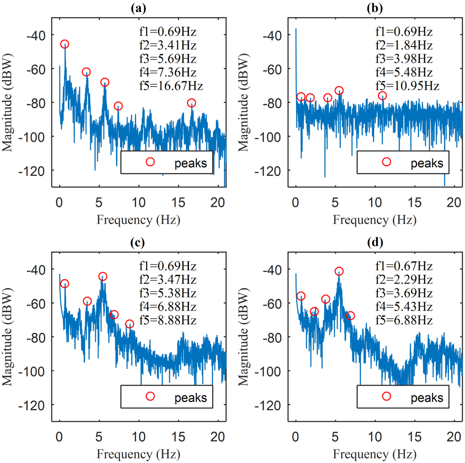
Power spectrums of the static response vibration signals: (a) tower radial direction, (b) tower axial direction, (c) nacelle radial direction, and (d) nacelle axial direction.
In the radial direction of the tower, most power focuses on f1 = 0.69 Hz in the power spectrum. In the axial direction, the highest frequency is f4 = 5.48 Hz which take more power energy in the power spectrum. Hence, the natural frequency of the tower is 0.69 Hz in the radial direction and 5.48 Hz in the axial direction based on the static response experiment. Similarly, the natural frequency of the nacelle is 5.38 and 5.43 Hz in the radial direction and axial direction respectively, as shown in Figure 9(c) and (d).
For the purpose of reducing the influence of high frequency noise, the low-pass filtering is applied to the raw signals in the shock response experiment. The power spectrums of the shock response vibration signals are illustrated in Figure 10. There is only one distinguished peak frequency in the radial direction of the tower, that is f1 = 0.57 Hz. Hence, the natural frequency of the radial direction is 0.57 Hz from the shock response signal. The frequency of the highest peaks in the axial direction of the tower is f2 = 5.46 Hz. The natural frequency of the nacelle is 0.68 Hz in both directions based on the shock response.

Power spectrums of shock response vibration signals: (a) tower radial direction, (b) tower axial direction, (c) nacelle radial direction, and (d) nacelle axial direction.
According to the mutual influence among the wind turbine components, the natural frequency of one direction may be represented in both direction signals. Peaks of the natural frequency based on the static response and the shock response are listed in Table 3. The first-order peak is lower than 1 Hz, which can be found in all vibration signals. This indicates the first natural frequency for the wind turbine in the radial direction. This low frequency is essentially affected by the stiffness of the tower, as the shear and bending moment action on one side supported beam. The vibration in the axial direction of the wind turbine is mainly caused by the interaction between the nacelle and the tower. The highest natural frequency is focused on about 5.40 Hz in the axial direction both on the tower and on the nacelle.
Peaks of natural frequency based on the static response and the shock response.

The maximum energy value in the power spectrum is shown in bold.
Discussion
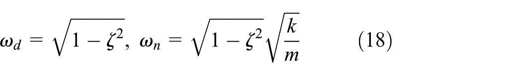
Compared to the static response and shock response experiments, the wind turbine study in this article has a radial direction natural frequency close to 0.57–0.69 Hz and an axial direction natural frequency close to 5.38–5.70 Hz. Without loss of generality, in this article we choose f0 = 0.69 Hz in the radial direction and f0 = 5.40 Hz in the axial direction as the first natural frequency of the wind turbine, respectively. As shown in Figure 4, the vertical stiffness of nacelle can be determined when the natural frequency of the nacelle in the axial direction is given. According to equation (18), the top mass stiffness of the vertical direction
In order to examine the effects of the stiffness in the proposed model, different combinations of the parameters have been investigated. For example, a point of intersection where kr = 35.35 GN m/rad, kl = 1.45 GN/m, and kh = 1.16 GN/m and the natural frequency f0 = 0.69 Hz is chosen to analyze the different effects of the three stiffness parameters. The variation of
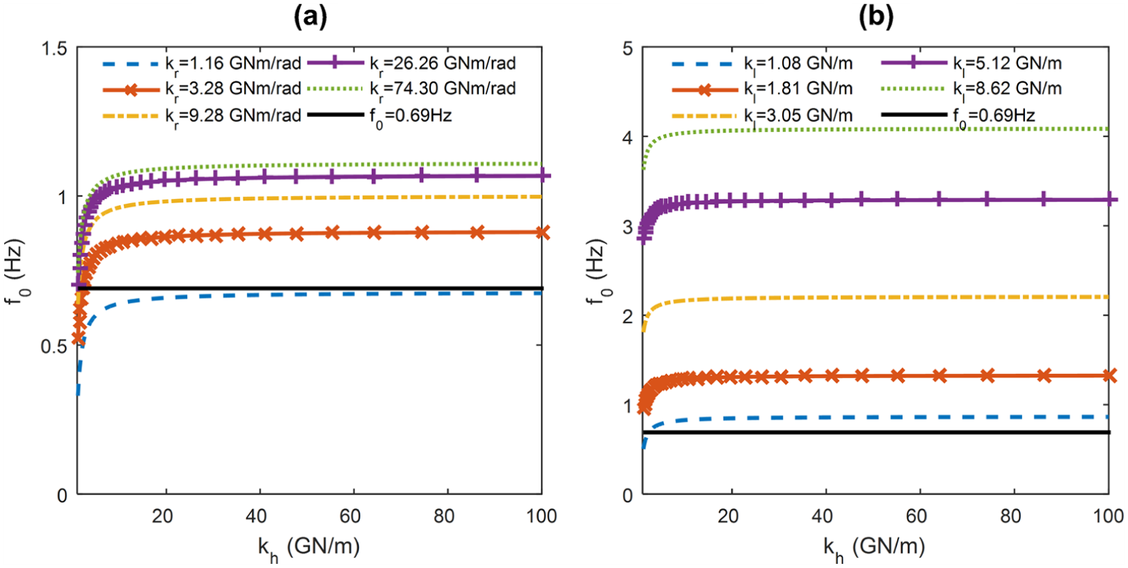
The first natural frequency of the wind turbine with respect to the foundation lateral stiffness

The first natural frequency of the wind turbine with respect to the foundation lateral stiffness

The first natural frequency of the wind turbine with respect to the foundation lateral stiffness
Based on the numerical simulation solutions and the experimental results, the stiffness parameters can be determined when one of the three is given. According to this, the stiffness parameters of the proposing model will be determined. However, during the wind turbine design phase, the proposed model can be utilized to improve the performance of the wind turbine by choosing suitable materials and structures with different stiffnesses to avoid the resonant frequency range. In the condition monitoring system, the natural frequency can be quickly identified among the abnormal frequency of the wind turbine system.
Conclusion
This article provides an improved dynamic analysis model in order to investigate the effects among the tower–nacelle–foundation system in wind turbine in case of incomplete structural parameters. A mathematical model of the wind turbine has been formulated using Euler–Lagrangian approach. A closed-form expression of the characteristic equation is given. Numerical simulations have been carried out using realistic data from a 1.5-MW wind turbine and a 5-MW wind turbine. The natural frequencies of the system have been carried out by the present methods and FAST. The results indicate that the presented model is able to describe the dynamic behavior of the wind turbine under incomplete structural parameters. The vibration signal of wind turbine acquired by the condition monitoring system is used to validate the proposed method. Results show that the calculated and measured natural frequencies are reasonably close.
The main aim of this study was to show how the proposed simplified model could be successfully used for analyzing the dynamic characteristic of the tower–nacelle–foundation system in the wind turbine. The modal expressions derived in this article can be used for checking the model parameters verifying and improving analytical models contrasting experimental to analytic data. Moreover, it can be utilized for estimating the dynamic property of the wind turbine in the design phase.
Further investigations are needed for considering the behavior of the blade system and environmental condition (such as the wind speed, wind direction, and temperature) for onshore and offshore wind turbines.
Footnotes
Appendix 1
Academic Editor: Crinela Pislaru
Declaration of conflicting interests
The author(s) declared no potential conflicts of interest with respect to the research, authorship, and/or publication of this article.
Funding
The author(s) disclosed receipt of the following financial support for the research, authorship, and/or publication of this article: This research was supported by the National Natural Science Foundation of China (grant nos 51305258 and 61175038) and National Key Technology R&D Program (2014BAA04B01 and 2015BAF11B01).