
Abstract
The hydraulic locking sleeve is a key component of precision instruments such as five-axis machine tools, giant astronomical telescope, and satellite antenna. This is subjected to the action of pressure load causing large elastic deformation and locking the rotational freedom of feed shaft at any angle. The maximum locking torque is an important parameter for designing the hydraulic locking sleeve. First, the hydraulic locking sleeve is simplified as elastic thin cylindrical shell structure. Neglecting the bending and twisting effects, the calculation equations describing the deformation and stress state between the hydraulic locking sleeve and rotary shaft are derived by applying the theory of elastic thin shell. Then, taking into account that one end of the hydraulic lock sleeve is fixed to the shaft sleeve seat by the end face flange; the calculating formula of the maximum locking torque of the hydraulic locking sleeve is obtained by modifying the deformation equation based on moment model. Finally, a test platform of hydraulic locking sleeve is designed, which can measure the maximum locking torque of the hydraulic locking sleeve. The error between the calculation result of locking torque theoretical calculation model and the experimental measured value is <15%. As a result, the causes of the error are analyzed, and the effects of the shaft sleeve length, wall thickness, and radius on the maximum locking torque are calculated.
Keywords
Introduction
Commonly, five-axis computer numerical control machine tools consist of three linear feed shafts and two rotary feed shafts. When machining complex parts, it needs not only the continuous feeding of the rotary feeding shaft to realize multi-angle machining but also the function of positioning and locking to machine in the specific direction.1–3 The lens diameter of the giant astronomical telescope could reach 20 m. When searching for target at the starry sky, the rotary table used for bearing lens needs to rotate around two axes; when observing celestial bodies, the rotary shaft needs to be accurately located and reliably locked.4,5 In the same way, the rotary shafts of the precision instruments such as satellite antenna and high power laser also need to have the function of positioning and locking.6–8
Hydraulic locking sleeve will generate a large elastic deformation under the action of liquid pressure, and the rotary shaft can be locked at any angle. The elastic deformation of shaft sleeve can be quickly restored after pressure relief of hydraulic system, and the rotary shaft can rotate freely again. Hydraulic locking sleeve can provide large locking torque. Its locking and releasing action is quick and will not interfere with the location accuracy of rotary shaft. Therefore, it is widely used in precision instruments because of its compact structure and high reliability.9,10 The locking torque is an important parameter of hydraulic locking sleeve. The magnitude of locking torque could be greatly influenced by the parameters such as shaft sleeve length, thickness, radius, oil pressure, and the gap between the rotary shaft and the locking sleeve.8,11–13 Hydraulic locking sleeve will be produced in the mode of single piece or small batch according to different application requirements. It is difficult to design a universal testing device to test the locking torque with the various specifications of hydraulic locking sleeve. Therefore, the accurate calculation of the locking torque is the key and difficult problem in the design of hydraulic locking sleeve.14,15 In the past, the clearance between the shaft sleeve and the rotary shaft is ignored at the time of the calculation of the locking torque of hydraulic locking sleeve, but in fact, the locking torque is very sensitive to the clearance values.16,17
In this article, the hydraulic locking sleeve is simplified as elastic thin cylindrical shell structure. By virtue of the elastic thin shell theory, the calculating method of the stress and locking torque between the hydraulic locking sleeve and rotary shaft is deduced. At last, the calculating results are verified with the fulfillment of experiments.
Structure and working principle of hydraulic locking sleeve
Hydraulic locking sleeve is a thin cylindrical shell structure, as shown in Figure 1. Figure 2 is a diagram of working principle of hydraulic locking sleeve. The shaft sleeve is fixedly connected to the shaft sleeve seat by the end face flange. A closed hydraulic oil chamber is formed between the outer cylinder surface of shaft sleeve and the shaft sleeve seat. There is a small clearance between the rotary shaft and the inner cylinder surface of shaft sleeve, and the rotary shaft can rotate freely, as shown in Figure 2(a).

Hydraulic locking sleeve.

Diagram of working principle of hydraulic locking sleeve. (a) Free state of hydraulic locking sleeve and (b) locking state of hydraulic locking sleeve.
The thin-walled part of shaft sleeve will yield elastic deformation under the action of pressure when high pressure oil enter the hydraulic oil chamber, so that the rotary shaft is locked, as shown in Figure 2(b). Hydraulic locking sleeve will return to the initial state when the hydraulic oil chamber relieves the pressure, thus the rotary shaft can rotate freely again.
Testing scheme of locking torque
The test rig of the hydraulic locking sleeve shown in Figure 3 is designed for testing the maximum locking torque of shaft sleeve. In the testing process, the pressure oil chamber maintains a constant pressure to make the shaft sleeve lock the rotary shaft. Then slowly increasing the output torque of the hydraulic motor which will be automatically recorded by acquisition instrument, the hydraulic motor will not stop loading until the rotary shaft commits the rotation and triggers the stroke switch. At this time, the torque recorded by the acquisition instrument is exactly the maximum locking torque of shaft sleeve under this pressure. The photograph of the test rig is shown in Figure 4.

Diagram of working principle of the test rig of the hydraulic locking sleeve.

Testing rig of the hydraulic locking sleeve.
Theoretical calculation method of locking torque
When the hydraulic locking sleeve is locked and if the rotary shaft rotates relatively to the shaft sleeve, the inner surface of shaft sleeve is easy to scratch. Furthermore, shaft sleeve is generally produced in the mode of single piece or small batch when used for precision instruments such as five-axis machine tool, giant astronomical telescope, and satellite antenna. It is difficult to design experimental device for each type of shaft sleeve; thus, the design of shaft sleeve is in need of a relatively accurate theoretical algorithm.
Calculation of membrane theory
The hydraulic locking sleeve is simplified as elastic thin cylindrical shell structure, as shown in Figure 5.18,19 It is assumed that there are not any bending moment and torque, but the longitudinal load component q1, circumferential load component q2, normal load component q3, longitudinal pull pressure FT1, circumferential tension pressure FT2, and membrane forces FT12 = FT21 on all cross sections of the shell are shown in Figure 3. In Figure 5, the coordinates α and β represent the generatrix and traverse directions of cylinder, respectively.

Distribution of shell internal force.
The curvature of the middle surface along the direction of α is k1 = 0, and the curvature along the direction of β is k2 = 1/R. According to the membrane theory of the cylindrical shell, the equilibrium equation and the kinematic equation of cylindrical shell can be expressed as

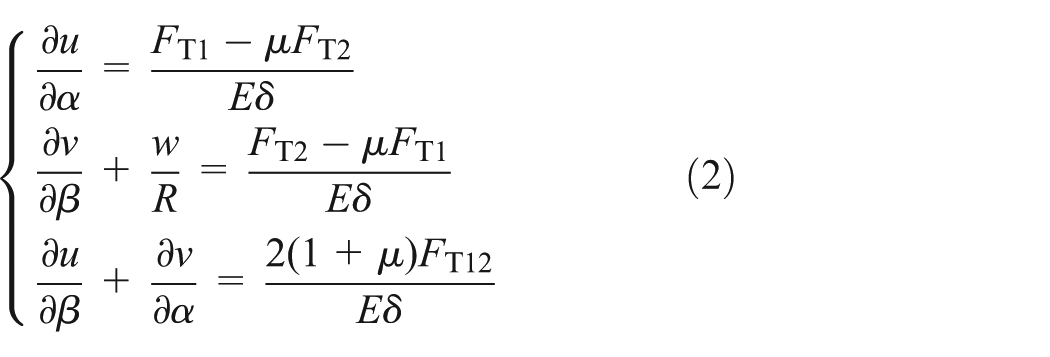
where u, v, and w are the axial displacement, circumferential displacement, and normal displacement of a point in middle surface of the cylindrical shell, respectively.
The simplified model of the cylindrical shell by membrane theory is shown in Figure 6, and the shaft sleeve only bears uniform external pressure q0. It is assumed that both ends of shaft sleeve are fixed, whose length is L, wall thickness is δ, and curvature radius of the middle surface is R (middle radius), so q1 = 0, q2 = 0, q3 = q0. In order to be convenient to consider boundary conditions, α = 0 is exerted on the end of hydraulic locking sleeve, thus forming the boundary conditions as follows


Simplified mechanical model of hydraulic locking sleeve by membrane theory.
According to the formula (1), the circumferential tension can be written as

Replacing it into the second formula of the formula (1), the equation can be obtained as

And then

According to symmetry, the following formula can be deduced

Namely

Inserting it in the second formula of equation (1), and combining it with the boundary conditions of equation (3), we have

Substituting the previous result into the first formula of the formula (2), the following equation can be obtained
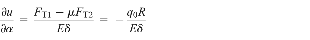
Taking into account the structural symmetry, that is, u(α = L/2) = 0, integration of the latter expression with respect to α yields

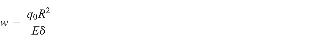
Inserting it in the third formula of equation (2) and combining it with the boundary conditions of equation (4), we obtain

Substituting it into the second formula of the formula (2) results in
Modification of moment theory
Membrane theory assumes that there is no bending moment and torque on all cross sections of the shell, which simplifies the derivation process of the equation of deformation. 20 In order to make the calculation result be closer to the true value, it is necessary to modify the equation of deformation with the moment theory.
It is assumed that the axial length in the minimum wall thickness of the hydraulic locking sleeve is 2l. The midpoint is taken as α = 0, and radius of curvature of the middle surface is R (radius). When the hydraulic locking sleeve is fixed at one end, its mechanical model is shown in Figure 7. In the figure, M is the bending moment, and Q is the shear stress.

Mechanical model of hydraulic locking sleeve using the moment theory of shell.
Here, q1 = 0, q2 = 0, the basic differential equation is represented as

Introducing the displacement function F = F(α, β), the transverse deflection of the shell middle surface can be expressed as

where

Thereby, the fundamental differential equation for F(α, β) can be written in the following form

where

Since both the load and the deformation of the hydraulic locking sleeve possess symmetry, F(α, β) depends on only α, y = F(α).
Accordingly, partial differential equation (7) can be replaced with the following ordinary differential equation

where w is the four-order ordinary differential equation.
In order to simplify the basic differential equation, we introduce the notation λ

And the following coordinate of non-dimension is employed

In this way, differential equation (8) can be rewritten as
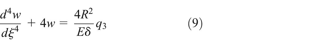
Its solution can be written as the following form
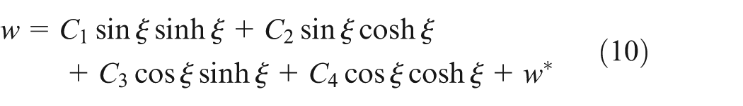
where w* is any particular solution, which can be chosen according to the requirement of the differential equation (9) and the function form of the normal load q3. The constants C1, C2, C3, and C4 depend on the boundary conditions. In order to be convenient to use the symmetry, α = 0 is committed in the central cross section (symmetry surface), as shown in Figure 7.
The membrane theory is the special circumstance of the moment theory of the shell; thus, the solution of the membrane theory can be regarded as one of the particular solution of equation (10), namely

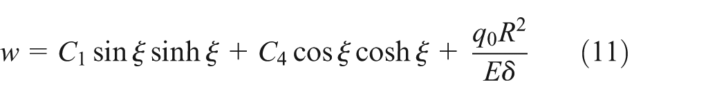
Because of the symmetry, w should be the even function of ξ. For this reason C2 = C3 = 0, thus the general solution can be written in the form
When one end of the hydraulic locking sleeve is fixed constraint, as shown in Figure 7, there are the following boundary conditions

Introducing formula (11) into the boundary conditions (12), the results can be obtained as

Solving the system of equation (13) for C1 and C4, the transverse deflection of the cylindrical shell can be expressed as

Considering the clearance between the sleeve and the rotary shaft
There is an initial clearance δ1 between the hydraulic locking sleeve and rotary shaft. The initial clearance could not be eliminated until the pressure of hydraulic oil reaches qc

It can be seen from formula (15) that q1 is the function of ξ (or α), thus the effective pressure exerted to the rotary shaft is

Namely, the pressure p1 (α) of the rotary shaft is non-uniform distribution, and it changes with α. Through the integral of the pressure p1 (α) on the interval of [−l, l], the transmitted locking torque can be represented as

where T is locking torque and f is friction coefficient between the shaft sleeve and rotary shaft.
Numerical calculation and experiment of hold torque
During the design of the hydraulic locking sleeve, the effective length of shaft sleeve is l = 70 mm, shaft sleeve radius is R = 51 mm, wall thickness is δ = 4 mm, and the unilateral clearance between the hydraulic locking sleeve and rotary shaft is δ1 = 0.02 mm. The hydraulic locking sleeve is made of tin bronze material, and the rotary shaft is made of No. 45 steel. The material properties of the hydraulic locking sleeve and rotary shaft are shown in Table 1.
Material properties of the hydraulic locking sleeve and rotary shaft.

As the pressure of the hydraulic oil is gradually increased up to q0, the locking torques of shaft sleeve obtained by numerical methods and experimental methods are shown in Figure 8.

Relation curve between the maximum locking torque of shaft sleeve and hydraulic oil pressure.
As can be seen in Figure 8, when hydraulic oil pressure is lower than 2 MPa, there exists a clearance between the shaft sleeve and rotary shaft, and the shaft sleeve cannot achieve the locking function. The maximum locking torque of shaft sleeve is in direct proportion to the hydraulic oil pressure when hydraulic oil pressure is higher than 3 MPa. Hydraulic oil pressure is lower, and the test value is lower than the calculated value. In addition, the lower the oil pressure, the larger the error, since the error is larger when the torque sensor is in lower value; when hydraulic oil pressure is higher, the test value is larger than the calculated value, since the actual friction coefficient augments with the increase of contact area and contact pressure.
Analysis of influence factors of locking torque
In order to make the shaft sleeve reach the required maximum locking torque, the solutions contain either the increase of the radius and length of the sleeve or the hydraulic oil pressure, or the decrease of the wall thickness or the clearance between the shaft sleeve and rotary shaft. On one hand, it is necessary to take into account the design requirements of rotary shaft and other related components, as well as calculate the machining cost, on the other hand; it is necessary to know how these factors affect the locking torque of hydraulic locking sleeve. In this work, the relationship between the maximum locking torque and the influence factors is analyzed. The influence factors include the sleeve radius, wall thickness, length, hydraulic oil pressure, and the clearance between shaft sleeve and rotary shaft.
First, keeping the effective length of shaft sleeve 2 l = 70 mm, hydraulic oil pressure q0 = 5 MPa, wall thickness δ = 4 mm, and the clearance between shaft sleeve and rotary shaft δ1 = 0.02 mm, the relationship between the shaft sleeve radius R and locking torque T calculated by the theoretical method is shown in Figure 9. As shown in Figure 9, the locking torque of sleeve increases with the addition of the shaft sleeve radius R in the case that other parameters keep constant.

Locking torque of shaft sleeve with different inner radius.
Keeping the effective length of shaft sleeve 2 l = 70 mm, shaft sleeve radius R = 51 mm, hydraulic oil pressure q0 = 5 MPa, and the clearance between shaft sleeve and rotary shaft δ1 = 0.02 mm, the relationship between the wall thickness δ and locking torque T calculated by the theoretical method is shown in Figure 10. As shown in Figure 10, the locking torque of shaft sleeve is approximately in inverse proportion to the wall thickness in the case that other parameters keep constant.

Locking torque of shaft sleeve with different wall thicknesses.
Keeping the inner radius of shaft sleeve R = 51 mm, wall thickness δ = 4 mm, hydraulic oil pressure q0 = 5 MPa, and the clearance between shaft sleeve and rotary shaft δ1 = 0.02 mm, the relationship between the effective length of shaft sleeve and locking torque T calculated by the theoretical method is shown in Figure 11. As shown in Figure 11, the locking torque of shaft sleeve is in direct proportion to the effective length of shaft sleeve in the case that other parameters keep constant.
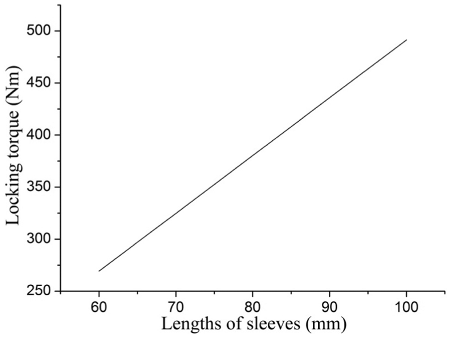
Locking torque of shaft sleeve with different effective lengths.
Keeping the effective length of shaft sleeve 2 l = 70 mm, inner radius of shaft sleeve R = 51 mm, wall thickness δ = 4 mm, and the clearance between shaft sleeve and rotary shaft δ1 = 0.02 mm, the relationship between the hydraulic oil pressure and locking torque T calculated by the theoretical method is shown in Figure 12. As shown in Figure 12, when the hydraulic oil pressure is between 2 and 3 MPa or larger than 3 MPa, the locking torque of shaft sleeve is in direct proportion to the hydraulic oil pressure. In addition, the ratio of the latter is larger, which means that when the hydraulic oil pressure is larger than 3 MPa, the locking torque of shaft sleeve is more sensitive to the pressure of hydraulic oil.

Locking torque of shaft sleeve with different pressures of hydraulic oil.
Keeping the effective length of shaft sleeve 2 l = 70 mm, inner radius of shaft sleeve R = 51 mm, wall thickness δ = 4 mm, and hydraulic oil pressureq0 = 5 MPa, the relationship between the clearance between sleeve and the shaft and locking torque T calculated by the theoretical method is shown in Figure 13. As shown in Figure 13, the locking torque of shaft sleeve decreases with the increase in the clearance between shaft sleeve and rotary shaft in the case that other parameters keep constant. The larger the clearance, the smaller the decreased magnitude.

Locking torque of shaft sleeve with different clearances.
Conclusions
In terms of the theory of elastic shells, the calculating formula of the maximum locking torque of hydraulic locking sleeve is deduced. A test rig of the hydraulic locking sleeve which could be used to measure the maximum locking torque of the shaft sleeve is developed. The error of locking torque between the theoretical calculation result and the experimental measurement value is <15%. The main cause of the error is that the friction coefficient between the shaft sleeve and rotary shaft changes with the contact area and contact pressure. The theoretical calculation model could meet the precision requirement for the design of hydraulic sleeve.
Besides, the influences of different factors on the sleeve locking torque are calculated and analyzed. The locking torque of sleeve gradually increases with the addition of the sleeve radius, the effective length, and the pressure of hydraulic oil, but gradually decreases with the addition of the wall thickness of sleeve and the clearance between the shaft sleeve and shaft.
Footnotes
Academic Editor: Mohana Muthuvalu
Declaration of conflicting interests
The author(s) declared no potential conflicts of interest with respect to the research, authorship, and/or publication of this article.
Funding
The author(s) received no financial support for the research, authorship, and/or publication of this article.