
Abstract
In this study, multilayer carbon-fiber-reinforced plastic sheets with various pre-impregnated thicknesses were developed. Specimens were fabricated by the hand lay-up process from standard and thin-ply unidirectional carbon fiber/epoxy resin prepreg sheets, which were also cured in an autoclave. Tensile tests from room temperature to 120°C and interlaminar shear strength tests at room temperature were first conducted to investigate the mechanical behavior of the laminated carbon-fiber-reinforced plastic sheets. Furthermore, with a view to increase the formability, in this study, a state-of-the-art drawing process for laminated carbon-fiber-reinforced plastic sheets at an elevated temperature was investigated, and the drawing ratio was also determined for the case of elliptical cup drawing. To achieve this, the relation between the punch load and stroke, and the distribution of thickness were determined by measurement. To clarify the forming behavior in this case, evaluation of the effect of increasing the number of drawing steps was performed to investigate the deformation history. The microstructures showed reduced delamination with increasing radius of the punch. The experimental results obtained in this study are expected to help designers perform the press forming of multilayer carbon fiber/epoxy resin sheets.
Keywords
Introduction
Social needs are promoting the development of forming technologies for lightweight parts. There has been increasing use of composites worldwide in diverse sectors to reduce energy use. The Boeing 787 makes much more extensive use of composites in its airframe and prime structure than previous Boeing commercial airplanes. 1 The shaping potential of carbon-fiber-reinforced plastic (CFRP) is nearly limitless and its most pronounced advantage over metals is its wide range of applicability, leading to efficient material employment. 2 For Lexus LFAs, the CFRP body structures formed by resin transfer molding (RTM) or the sheet molding compound (SMC) process have replaced those of conventional materials such as alloys and steel. 3 The increased use of RTM or SMC to manufacture CFRP structures may reduce the cost and the production cycle time required to manufacture CFRP parts, increasing the flexibility of the manufacturing process. A novel press-forming method for CFRP sheets for their use as lightweight parts has been proposed, 4 which is an attractive alternative to the RTM and SMC. By stamping solidified CFRP sheets under cold and warm conditions, high-strength structures can be formed with high productivity and a low cost. For the stamping of CFRP sheets while maintaining their strength, methods for achieving high strength and formability for various structures are necessary. The fundamental deformation properties of unidirectional (UD) and cloth layers were evaluated, and an idea for optimizing the lamination of CFRP sheets using UD and cloth layers was proposed. 5 The investigation of the press-forming behavior of these materials is an area of special interest. In particular, a new method combines a generic algorithm with the finite element method (FEM) to arrange the layer structure in the design of CFRP composites with a suitable ply structure for stamping. 6 The press forming of CFRP sheets was simulated by implementing a commercial code to investigate the formability for both the macroscale and the meso/macroscale, and the FEM results were also in agreement with experimental results. 7 Using the benefits of glass-fiber-reinforced plastic (GFRP) with mechanical properties equivalent to those of steel, the weight of automobile parts can be decreased without any decrease in mechanical performance. 8 Recently, a design optimization process combined with impact analysis was developed for a hybrid glass/carbon composite bumper, which was then manufactured. 9 The effect of introducing reinforcement materials, as well as the use of different forming tools, has been discussed.
Although the principal manufacturing process of CFRP structures has been SMC or RTM, press forming has considerable potential because of its competitive productivity and performance, reducing cost and production time out of RTM or SMC with CFRP composites. Among the fabrication processes involving press forming, the drawing of laminated CFRP sheets is especially important for the rapid production of parts, even those with complex shapes such as vehicle parts including B-pillars and panels. Thin-ply CFRP sheets can be easily manufactured with tow-spreading technology, which is a new low-cost process with high productivity.10,11 Nevertheless, the difference in the amount of damage during operation between standard (thick-ply) and thin-ply laminates is considered to originate from the effect of the ply thickness. 12 Moreover, the residual strength of thin-ply non-crimp fabric composites with large through-thickness cracks was examined, and experimental research on the mechanical response of a new series of advanced composite materials manufactured using thin non-crimp fabrics has been reported. 13 Tensile and compressive tests on both unnotched and notched specimens were performed using various lay-up processes. 14 The variation in mechanical properties in terms of the tensile strength and elastic modulus of CFRP, GFRP, and CFRP/GFRP hybrid composites exposed to different temperatures ranging from 25°C to 300°C was also studied. 15 In addition, analytical models for predicting tensile strength and elastic modulus of fiber-reinforced plastic (FRP) composites at elevated temperatures were also proposed. 16
The aim of this study is to investigate the possibility of press-forming multilayer CFRP sheets made with a defined specific stiffness and strength using CFRP pre-impregnated sheets with different thicknesses. Press forming is dominated by the formability of the material. As a result, knowledge of the material formability is essential for the design and architecture of any industrial forming process such as simulations employing the FEM, forming criteria, and tool design. Hence, the formability of multilayer CFRP sheets was investigated using an experimental approach. The multilayer CFRP sheets were fabricated with various pre-impregnated thicknesses and evaluated by various quality assessment methods. Since a CFRP usually exhibits limited ductility at room temperature, the mechanical properties of a laminated CFRP can be improved by increasing the temperature. The mechanical and forming properties of multilayer CFRP sheets are presented and discussed for standard and thin-ply composites on the basis of the results of tensile tests at various temperatures ranging from room temperature to 120°C, and drawing tests at 120°C were performed. In addition, the important forming characteristics of the laminated CFRP sheets such as the drawing ratio (DR) were also examined in experiments. Furthermore, the deformation history, the relationship between the punch load and stroke, and the distribution of thickness were also studied. The results of other shaping conditions such as a larger radius of the punch are also given in this article.
Experimental procedures
Fabrication of specimens
The material properties and drawing behavior of the standard laminate and thin-ply laminate are compared. Due to the effect of the ply thickness of carbon/epoxy, composites with various ply thicknesses (30–300 g/m2 prepreg weight per area (PPAW)) were investigated in terms of the ultimate strength and the onset of damage in lamina, laminates, and components. 17 Besides, the damage process was quite different; accumulation and growth of delamination and matrix cracks were observed in standard composites, while sudden fiber fractures occurred in thin-ply composites. 12 As shown in Table 1, the material systems used in this study were standard (149 g/m2 PPAW) and thin-ply (62 g/m2 PPAW) UD carbon/epoxy prepreg sheets fabricated by the hand lay-up process. The standard sheets were P3252S-10 sheets with T-700SC carbon fibers from TORAYCA, Japan. Thin-ply Mitsubishi Rayon TR50S carbon fiber/Bisphenol-A prepreg sheets were supplied by Industrial Technology Center of Fukui Prefecture, Japan. The nominal volume fraction of carbon fibers and the filament diameter for both pre-impregnated sheets were 58% and 7 µm, respectively. The symmetrical stacking sequence [0/90/0]1S had a high tensile strength of 1400 MPa along the fiber direction and an excellent elongation of 25% at an angle of 45° to the fiber direction.5,6 Accordingly, a standard [0/90/0]NS laminate and a thin-ply [0/90/0]NS laminate were prepared in this study. Here, NS stands for the number of symmetrical layers. All specimens were fabricated by the hand lay-up process and then cured in an autoclave under an applied pressure of 0.5 MPa and a temperature of 130°C for both the standard and thin-ply composites. The nominal thickness of the fabricated standard [0/90/0]3S and thin-ply [0/90/0]8S laminates subjected to property tests was 2.0 mm. Furthermore, the nominal thickness of the standard [0/90/0]1S and thin-ply [0/90/0]2S laminates subjected to drawing tests was 0.6 mm.
Characteristics of unidirectional (UD) prepreg sheets.
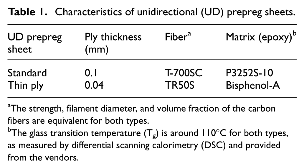
The strength, filament diameter, and volume fraction of the carbon fibers are equivalent for both types.
The glass transition temperature (Tg) is around 110°C for both types, as measured by differential scanning calorimetry (DSC) and provided from the vendors.
The autoclave and the process timing of the autoclave used for the consolidation of multilayer CFRP sheets are shown schematically in Figure 1. To ensure effective curing by the autoclave, the laid-up CFRP sheet was covered with a vacuum bag and connected to a vacuum system as shown in Figure 1(a). It is essential to comprehend the effects of the curing temperature, curing time, and the bagging vacuum and autoclave pressures, because these parameters affect two major physical properties: the glass transition temperature (Tg) and the void content. As shown in Figure 1(b), the temperature was increased from room temperature to around Tg at a rate of 2°C/min, and this temperature was maintained for 30 min to ensure that the thermosetting resin changed from the glassy state to a more balanced rubber-like state. Then, the sample was further heated to the curing temperature at the same rate, at which it was cured for 2 h. Finally, it was cooled to room temperature to obtain a cured laminated carbon fiber/epoxy resin sheet as shown in Figure 2.

Schematics of autoclave and its schedule: (1) seal, (2) vacuum bag, (3) vacuum channel to be connected to the vacuum pump, (4) test composite, (5) tool plate inside the chamber, (6) metal plate, and (7) release film (Teflon)—(a) autoclave and (b) process timing.

Cross sections of cured multilayer CFRP sheets: (a) standard type and b) thin-ply type.
Assessment of void content
A 3D x-ray microscopic computed-tomography (CT) scanner (TDM1000-IS/SP Yamato Scientific Co., Ltd., Japan) was used with VG-Studio MAX image analysis software (Volume Graphics Co., Ltd., Japan) to obtain a collection of tomographic images and measurements for the analysis of voids inside the specimens. The tomograms collected an energy of 45 kV and a current of 20 µA. The resolution of the tomograms was set to 10 µm. A specimen with dimensions of L20 mm × W10 mm × t2.0 mm was cut from the cured standard and thin-ply laminates. The image analysis software was used to measure the void content for each specimen per 100 µm in the thickness direction. As shown in Table 2, the nominal values of the measured void content for the standard and thin-ply laminates were 0.57% and 0.19%, respectively.
Assessments of void content for laminated CFRP sheets.

CFRP: carbon-fiber-reinforced plastic.
The measured values were taken as the nominal void content associated with each porosity level. Knowledge of the void content is essential and levels of above 1% are not permissible in advanced composite dynamic aerospace structures. In other structures, levels of 2% to 5% or higher are allowed. 18 Even so, the cost and void content are always related, and the acceptable void level is a critical topic in the design period. Designers can reduce the cost by knowing the tolerable void degree for particular applications.
Mechanical characterizations
To assess important material properties for the design of laminated carbon/epoxy composites subjected to transverse loads, short-beam shear tests were performed for mechanical evaluation. These tests were carried out at room temperature in accordance with ASTM D2344 to measure the interlaminar shear strength (ILSS) of multilayer CFRP sheets. The dimensions of the specimens were L12 mm × W4 mm × t2.0 mm. The span-to-depth ratio was 4:1, and the punch speed in the tests was 1 mm/min.
Moreover, the stress–strain relations are the primary information for studying the formability of multilayer CFRP sheets. The formability of a thermosetting CFRP sheet is limited at room temperature because of its state; hence, it can be heated to above Tg. To examine various tensile properties of multilayer carbon/epoxy sheets at different temperatures, tensile tests were performed at room temperature, 75°C, and 120°C with a test speed of 2 mm/min. As shown in Figure 3(a), the tensile tests were conducted using an MTS810 universal mechanical testing machine, with an MTS653 furnace device used for tests at elevated temperatures. The tensile test samples were prepared in accordance with ASTM D3039, and the nominal dimensions of the specimens were L250 mm × W25 mm × t2.0 mm. A typical configuration and the dimensions of the testing specimens are depicted in Figure 3(b). GFRP tabs were bonded at the extremities of the samples to prevent damage when clamping the test specimens. The specimens were cut along planes coinciding with the fiber direction (0°), as well as at angles of 45° and 90° to the fiber direction. During the tests, the temperature of the specimen was kept constant until the specimen was stretched to failure.
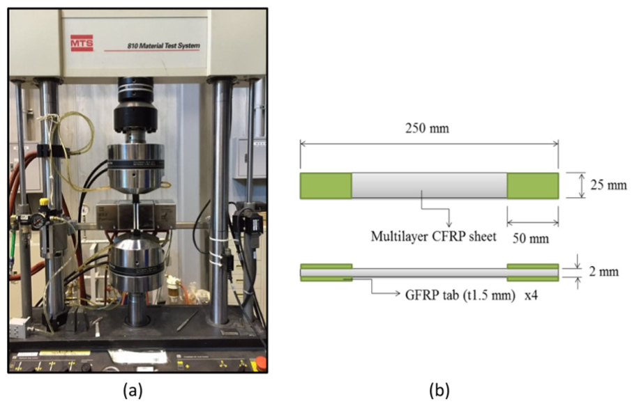
(a) MTS810 tensile test machine with MTS653 heater and (b) configuration of tensile specimen.
Setup of drawing process
In addition to determining the basic mechanical properties, the elliptical cup drawing was performed to calculate the DR for the multilayer CFRP composites. Furthermore, the relationship between the punch load and stroke, the thickness distribution, the deformation history, and so on, were examined through the drawing process. The dimensions of the elliptical shaft used for drawing were α = 5.25 mm × β = 3.5 mm, and the profile radius of the punch was 0.6 mm (Rp) as shown in Figure 4. Thus, the selected initial sheet had dimensions of □30 mm × t0.6 mm. The drawing process was executed using a 5-ton hydraulic servo press. Sandwich forming has previously been applied to the forming of solidified CFRP sheets with a dummy metallic sheet used in the process.4,5 In this case, aluminum alloy 1050 was chosen as the dummy sheet for sandwich forming, as shown in Figure 4, which has the benefits of increasing the bending radius when the elongation increases, as well as reducing defect formation in the compressive zone. Likewise, a polymer sheet can normally be easily formed by increasing the temperature to above Tg and stretching it into a mold with the desired shape. 19 In this study, dummy sheets were heated by an induction heating unit and held at the target temperature of 120°C.
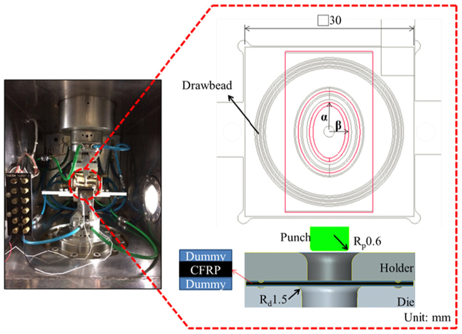
Schematic diagram of elliptical cup drawing process.
In a previous study, to calculate the forming limit of SUS304 stainless-steel sheets by the analysis of elliptical cup drawing, the DR (RDR), limit DR (RLDR), and overextended DR (REDR) were applied. 20 In this study, an appropriate elliptical cup drawing was used to estimate the DR for the multilayer CFRP composite. The DR in the elliptical cup drawing test is specified by DR = C/Cp, where Cp stands for the perimeter of the elliptical column of the punch and C is the circumference of the tested sheet without fracture. The DR was defined and calculated in this study.
Results and discussions
Analysis of mechanical properties
Physically, void removal by pressurization is feasible since curing in an autoclave causes void dissolution.21,22 We examined the effects of the curing pressure on the ILSS. Curing pressures of 0.2, 0.5, and 0.8 MPa were selected to produce composites to assess the effect of the curing pressure on mechanical properties. The ILSS of each type of laminate is plotted in Figure 5 as a function of curing pressure. The figure shows that the curves can realistically characterize the relationship between ILSS and curing pressure. These results are also consistent with those in previous works.23–25 As expected, the ILSS decreases at a lower curing pressure due to the higher void content of the laminates. Thus, pressure must be applied to the autoclave to reduce the void percentage to an acceptable level. For a particular application, an appropriate curing pressure according to the required void level when the other process parameters remain unchanged can be determined. However, the difference in the damage process between the standard and thin-ply laminates is considered to originate from the effect of the ply thickness. It is considered that thin-ply laminate has high damage resistance against matrix cracking and delamination near the back surface. 12
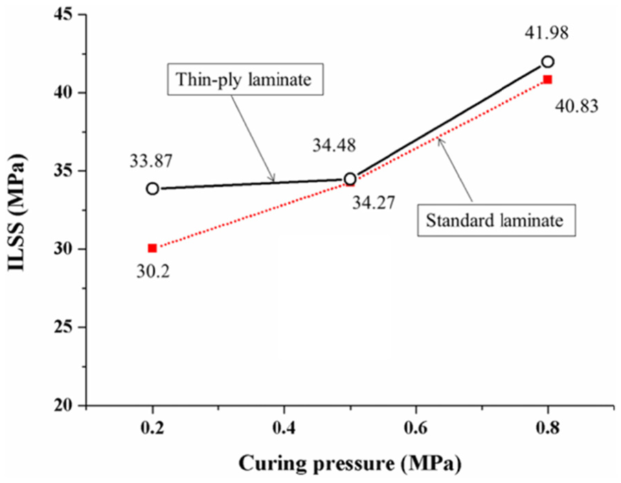
ILSS versus curing pressure.
Figure 5 also shows that the thin-ply laminate has greater performance in terms of ILSS than the standard laminate; these experimental results are also in agreement with the literature. 12 The experimental results show the advantage of thin-ply laminates over standard laminates in suppressing damage, suggesting their potential for incorporation into lightweight multilayer composites. However, for a given thickness or stiffness of the composite, the number of layers increases as the ply thickness decreases; thus, the number of possible stacking sequences increases. An appropriate optimization method is necessary to solve this problem.
We examined the effect of the forming temperature on the deformation of the multilayer CFRP sheets. The tensile tests were performed in three directions at room temperature, 75°C, and 120°C. The engineering stress–strain relations were obtained from the experimental data. Figure 6 shows the fracture of the 0°, 45°, and 90° samples tested at room temperature for thin-ply laminate. The appearance of each specimen shows that delamination and crack occurred inside the part where tension was applied to the specimen, and seldom layers were broken. However, the 0° and 90° samples subjected to tension at room temperature had the similar fracture on the transverse side, which was perpendicular to the fiber direction (0°). In contrast, a shear crack appeared in the 45° sample.

Specimens tested at room temperature (thin-ply laminate).
The engineering stress–strain curves of the standard [0/90/0]3S composite comprising the multilayer carbon/epoxy sheets at various temperatures were obtained from specimens with anisotropic behavior that were cut in three directions and are shown in Figure 7. It can be seen that the 0° specimen at room temperature has the highest ultimate tensile strength (UTS) of about 1500 MPa, whereas the largest elongation occurred for the 45° sample, the difference in elongation being more significant than that in the tensile strength. It was observed that the 45° sample displays extremely large strain of over 50%. The tensile strength orthogonal to the fiber direction was approximately 750 MPa, which is half that along the fiber direction (0°). Similarly, the engineering stress–strain curves of the thin-ply [0/90/0]8S composite comprising the laminated carbon/epoxy sheets at various temperatures were also obtained as shown in Figure 8. The nominal stress at room temperature was 1300 MPa along the fiber direction (0°) and the largest engineering strain was around 50% for the 45° sample. However, the elongation of the thin-ply [0/90/0]8S composite was less than 10% for the 90° sample. Clearly, a higher testing temperature resulted in lower strength, the fiber direction (0°) exhibited the highest tensile stress, and the largest strain occurred in the 45° sample.
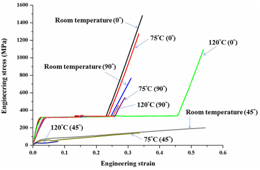
Stress–strain curves for standard laminate.
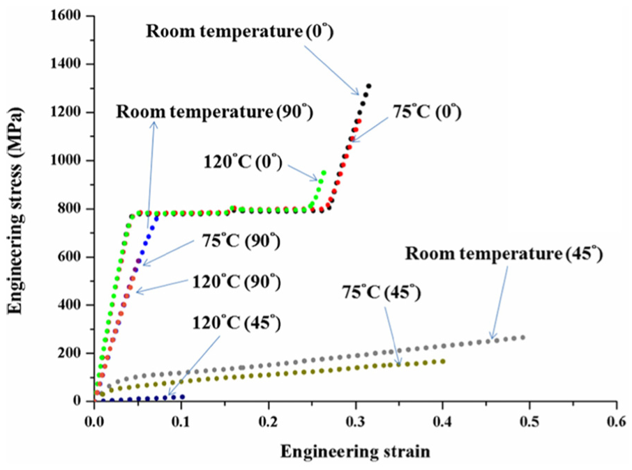
Stress–strain curves for thin-ply laminate.
Additionally, the strength of T-700SC carbon fibers is 4900 MPa and that of the epoxy matrix is estimated to be around 70 MPa. The most basic property of materials consisting of carbon fibers and epoxy is that they have different material properties from those of the individual materials. The strength of a composite is usually considered in terms of how much load it can resist before it suffers total failure. This breaking strength is the point at which the resin undergoes catastrophic breakdown and the reinforcing carbon fibers break. However, before the UTS was reached, the laminate will reach a stress level where the carbon fibers break or debond away from the matrix; these carbon fibers cannot withstand the high strain, and microcracks occur than spread through the resin matrix. Although the laminate has not completely failed at this stage, the breakdown process has commenced. As shown in Figures 7 and 8, the microcracks occurred in the 45° samples at room temperature of both the standard and thin-ply composites, and then the specimens withstood considerable strain of over 45%.
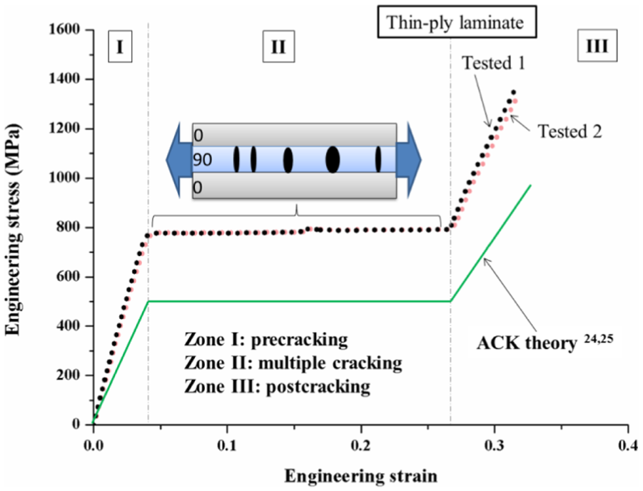
In detail, the theoretical tensile behavior of a composite with a brittle matrix in which the fiber-matrix bonds remain intact after the matrix has cracked is described in detail.26,27 The theory of Aveston, Cooper, and Kelly (ACK) 26 introduced simple ideas that are applicable to understand the stress–strain curve, as well as the type of cracking found in reinforced cements, plasters, and other brittle materials. The ACK model is able to explain why the stress–strain diagram can be divided into three areas as shown in Figure 9. In zone I, a crack forms along the fibers in a lamina. In zone II, with subsequent loading, more cracks form in the same lamina, referred to as multiple cracking. In zone III, known as postcracking, the fibers are being stretched or pulled out of the cracked matrix. The tensile curve based on the ACK model exactly fitted the results of our repeated experiments as shown in Figure 9. In a previous study, 28 the ACK model was found feasible to explain the tensile behavior of composites based on a cement/E-glass fiber mat.
ACK model.
Figure 10 shows the pseudo-ductility while multiple cracks occur during tensile test. Definition of yield stress (σy) and pseudo-ductile strain (εd) are also shown in Figure 10. The yield stress is defined as the cross point between the laminate stress–strain curve and a straight line of the initial modulus offset by 0.1% strain. The pseudo-ductile strain is the difference between the failure strain and the strain at the same stress level on a straight line of the initial modulus. 29

Graphical explanation of the pseudo-ductile curve.
An overall comparison of the standard and thin-ply laminates at room temperature is shown in Figure 11. The 90° sample of the standard laminate had a distinctive strain value, its larger strain at break than that of the thin-ply laminates, because notable multiple cracks exist in the same specific layer during tensile testing. Consequently, the UTS at 0° of both laminated CFRP sheets were approximately 1400 MPa, and the modulus of elasticity (E) and yield stress (σy) were then calculated as shown in Table 3. The elastic modulus of the standard composite was around 18 GPa at room temperature in the 0° sample, which is approximately 7% less than that of the thin-ply composite. Comparing the results obtained in the 0° sample at room temperature, the thin-ply composite exhibits approximately 167% greater yield stress and also agreement with that performs the better damage resistance than standard laminate. Also, the thin-ply composite presents approximately 14% lower tensile strength and about 7% higher elastic modulus than the standard laminate. Although the standard composite exhibited greater UTS and elongation, the thin-ply composite had a higher elastic modulus (E) and yield stress than the standard composite as shown in Table 3.
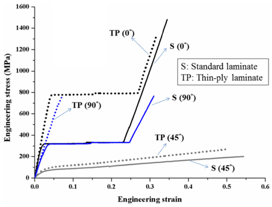
Comparison of stress–strain curves of standard and thin-ply laminates at room temperature.
Tensile test results for standard and thin-ply composites.

UTS: ultimate tensile strength.
Although brittle multilayer carbon/epoxy sheets at room temperature are less suitable for press forming than metals, they can be used for the sheet forming of relatively desirable products due to their formability above Tg. A large drop in stress in the stress–strain curves was observed above Tg. This also indicates that a stress–strain relation suitable for the drawing of laminated CFRP sheets can be obtained up to the forming temperature, which is slightly higher than Tg for epoxy of around 110°C. In other words, the thermosetting material becomes rubber-like when the specimen is heated to above Tg. Then, the matrix becomes more plastic at temperatures higher than Tg.
Briefly, the results of two different tensile tests on both standard and thin-ply composites are presented in Figures 7 and 8. As mentioned above, almost all of the multilayer CFRP composites display high strength for the 0° sample. As shown in Figure 11, the two different nominal stress–strain curves of the standard and thin-ply laminates at room temperature are similar; they both exhibited excellent properties with a tensile strength of above 1300 MPa and 30% elongation in the fiber direction. Accordingly, the most attractive feature of the CFRP composites is their strength-to-weight ratio; these composites have 20% of the mass of steel but similar strength and can potentially be used for lightweight automobile parts. A lighter weight and a low manufacturing cost per part are expected to result from replacing steel with various lightweight materials such as advanced high-strength steel (AHSS) and CFRP composites. 30 It was reported that AHSS has a lower cost than steel with a 20% mass reduction. Replacing the steel in current car structures with a CFRP composite could result in up to 60% mass reduction, although its cost is at least twice that of AHSS. However, are expensive and incompatible with existing manufacturing processes and have a higher production cost. These drawbacks prevent such materials from being frequently used, especially in low-end but high-volume production.
Elliptical cup drawing process
The DR, which is defined as the ratio of the circumference of the tested specimen (C) to the perimeter of the punch (Cp) in a successful cup drawing, is also a commonly used index to describe the formability of materials. In this study, the punch and die shown in Figure 4 were used for elliptical cup drawing tests. The punch profile radius (Rp) was fixed at 0.6 mm, and tests were performed at 120°C with a drawing speed of 1 mm/s.
Figure 12 shows the relations between punch load and stroke in the standard and thin-ply laminates. The forming depth increased from 4 to 5 mm when the drawing load decreased from 410 to 380 N for the standard laminate. However, the forming depth increased from 3 to 4 mm when the drawing load increased from 160 to 250 N for the thin-ply laminate. The fracture occurred outside the part at a stroke of 5 mm for the standard laminate and at a stroke of 4 mm for the thin-ply laminate. Consequently, as shown in Figure 13, few wrinkles appeared in the elliptical drawn cups. The DR was 4.46 for the standard composite with a stroke of 4 mm and 4.07 for the thin-ply composite with a stroke of 3 mm, indicating that the drawing of the multilayer carbon/epoxy sheet above its Tg is feasible. In shallow forming, evenly contoured shells such as automotive panels, the laminated CFRP sheet can be drawn over a punch. Figure 14 shows the microstructures of drawn cups at various strokes for both laminated CFRP sheets in the circular region and the side wall of the die and punch along the long axis. Delamination and voids occurred for both multilayer CFRP sheets formed with various strokes, even inside the microstructure of the drawn cups. The growth of delamination cracks occurred with deeper drawing while the shear stress of the interlayer was greater than the ILSS. This caused layers to separate with a marked decrease in mechanical toughness. However, if fracture appears in a drawing test, the blank-holder force can be reduced until the fracture is eliminated without the occurrence of wrinkles. When the adjustment of the blank-holder force fails to eliminate the fracture, the blank size can be reduced in an attempt to avoid fracture. The reverse methodology can be adopted to suppress the occurrence of wrinkles in a drawing test. 31 Similarly, in the press forming of a laminated CFRP sheet, these engineering problems such as wrinkles and necking might be solved by the optimization of the blank size and shape, the blank force, the die design, and so on.

Relations between punch load and stroke in drawing process.

Appearance of elliptical drawing cups: (a) stroke = 4 mm, (b) stroke = 5 mm, (c) stroke = 3 mm, and (d) stroke = 4 mm.

Microstructures observed during drawing for standard and thin-ply laminates: (a–c) standard composite and (d–f) thin-ply composite; (a) and (e) at stroke of 3 mm, (b) and (f) at stroke of 4 mm, (c) and (d) at strokes of 5 and 2 mm, respectively.
The most important issue in the drawing process is the thickness of the final product. The nominal thickness of the initial laminated carbon/epoxy sheet was 0.6 mm. Figure 15 shows the thickness distribution of standard and thin-ply composites for a 120°C drawing temperature and a stroke of 3 mm at each position (1–5) along the a- and b-axis. The obtained results show the thinning ratio for the standard and thin-ply laminates in the plate (positions 1 and 5), along the die profile radius (positions 2 and 4) and in the side wall (position 3). The thinning ratio is the difference in thickness as a percentage of the initial thickness. When the thickness decreases, the thinning ratio is positive; conversely, it is negative when the thickness increases. A thinning ratio of around 5% was observed regardless of the material at positions 1 and 5. Similar tendencies in the thinning ratio were observed at positions 2 and 4. At position 3, the thinning ratio was more than −30% for the standard composite in the direction of the long axis. There were irregular changes in the thickness due to the small radius of the punch, which hindered the flow of the matrix. As predicted, considerable delamination occurred in the clearly thickened region because the corner of the punch with a small radius did not allow the resin to flow smoothly, then a significant change in thickness occurred at the straight walls (position 3) when the delamination occurred. Hence, resin accumulated at the corners and thickening occurred at positions 2 and 4. Figures 14 and 15 also show that the thin-ply laminated composite exhibits less delamination damage between the layers than the standard laminate. These results for the performance of delamination resistance are also consistent with the results of a previous study. 12

Changes in thickness along standard laminate and thin-ply composite.
Reduction of delamination
Despite the successful elliptical cup drawing, the risk of delamination or other damage is high. Such damage can affect the mechanical properties of manufactured structures, reducing their reliability. The fabrication of high-quality parts with minimal damage is also crucial. In an attempt to reduce the formation of defects such as delamination, the radius of the punch increased from 0.6 mm (Rp) to 2.0 mm (Rmp). Images of cross sections of the drawn cups, obtained with an optical microscope, are shown in Figure 16. The figure also shows the microstructures of the multilayer carbon/epoxy composites in the round parts of the die and punch along the long axis. Upon increasing the radius of the punch, the degree of delamination decreased particularly between the different layers on the side wall and at the corners as clearly shown in Figure 16. This is because the resin more easily flows at the corner with a larger radius during the plastic deformation that occurs when the shearing stress is lower than the ILSS. However, it cannot be claimed that increasing the radius of the punch will be acceptable for all engineering designs.

Reduction in delamination by modification of the punch.
Conclusion
The mechanical properties and drawing process of multilayer CFRP sheets with various pre-impregnated thicknesses were investigated in this study. Drawing is a well-established process for manufacturing laminated CFRP structures. Providing a high strength-to-weight ratio of produced parts, it is one of the primary technologies in the vehicle industry used to satisfy energy roadmaps and for green design. In this study, the following findings were obtained:
New high-performance multilayer CFRP sheets were developed. They were fabricated with standard and extremely thin-ply prepreg layers and have noteworthy mechanical properties such as pseudo-ductile metal-like tensile stress–strain responses. The proposed laminated CFRP composites have approximately 1400 MPa strength and 30% elongation, compared to those of AHSS, giving it a sufficiently high strength-to-weight ratio for structural use. Thus, its use can reduce the mass of parts, improve their properties, and reduce their cost.
Better damage resistance using thin-ply carbon/epoxy prepreg of 0.04 mm thickness than standard one. Thin-ply [0/90/0]8S composite in particular shows the yield (σy) stress in excess of 700 MPa, as well as 167% higher than the standard [0/90/0]3S laminate. For modulus of elasticity (E), using thin-ply laminate is improved to 7% greater than standard laminate.
Elliptical cup drawing was performed using the laminated CFRP sheet above its glass transition temperature. The CFRP sheet was found to have a significant DR, this suggest that the drawing of multilayer CFRP sheets fabricated with standard and thin-ply prepregs can be used as a competitive means of manufacturing automotive shallow panels such as engine hood and roof.
The drawn cups were experimentally formed using a punch with radius of 0.6 mm. However, defects such as delamination were greatly reduced when the radius of the punch increased to 2.0 mm.
The experimental results obtained in this study provide fundamental guidelines for the use of press forming when designing the structures of multilayer CFRP composites.
Recommendation for future studies
CFRP composites have been growing in the fabrication of advanced structures for the aerospace, naval construction, or automotive sectors. The significant predicting in mechanical properties of CFRP composites has been needed in many product development stages, for example, design, simulation, and manufacturing. Accordingly, mechanical properties such as strength, resistance to damage, and resistance to thermal degradation should be investigated and improved in order to further expand their suitability in other applications. Furthermore, analytical models into these mechanical properties should also be undertaken in order to accurately account for these complicated mechanisms and benefit for predicting material properties.
Footnotes
Acknowledgements
The authors thank the Industrial Technology Center of Fukui Prefecture, Japan, for the thin-ply (0.04-mm-thick) unidirectional carbon/epoxy pre-impregnated sheets.
Academic Editor: Francesco Massi
Declaration of conflicting interests
The author(s) declared no potential conflicts of interest with respect to the research, authorship, and/or publication of this article.
Funding
The author(s) disclosed receipt of the following financial support for the research, authorship, and/or publication of this article: This study was supported by a Grant-in-Aid for Scientific Research (A) (90220194) provided by the Ministry of Education, Culture, Sports, Science and Technology (MEXT) of Japan.