
Abstract
The purpose of this article is to describe a deformation corrected workflow for maxillofacial prosthesis modelling based on the improved Laplace and iterative closest point–based iterative algorithms. For incomplete maxillofacial data with local deformed symmetrical features, the Laplace algorithm with rotation invariants was demonstrated that the operations can recover the local deformation while preserving the surface geometric detail; the M-estimation iterative closest point–based iterative algorithm integrated with the extended Gaussian image ensures the precision of the symmetry plane, making the outer point having almost no effect on the minimum process. The additional experiments also verified the ability of deformation corrected maxillofacial prosthesis modelling. Case study confirmed that this workflow is attractive and has potential to design the desired maxillofacial prosthesis for correcting the deformed oral soft tissue. The results of this study improve the quality of maxillofacial prostheses modelling. This technique will facilitate modelling of maxillofacial prostheses while helping the patients predict the effect before the prosthesis is manufactured. In addition, this deformation corrected workflow has great potential for improving the development of maxillofacial prosthesis modelling software.
Keywords
Introduction
Facial appearance plays a key role in interpersonal communication. However, due to facial defects involving the partial or total loss of some facial organs, there are some people suffering from severe psychological load. To assist them in relieving such psychological load, using facial prostheses may be a better alternative to restore their appearances to some satisfactory levels. Currently, instead of conventional fabricating techniques such as hand-curved and wax-cast, utilizing computer-aided design (CAD) and computer-aided manufacturing (CAM) systems to design and manufacture complex facial prosthesis has become the important trend. Several approaches have been proposed to use some commercial softwares for maxillofacial prosthesis modelling. For example, Evans et al. 1 used FreeForm to get the mirroring of the unaffected eye. Ciocca et al. 2 applied Rapidform (a reverse engineering software) to get the missing face by mirroring the contralateral healthy side. R Bibb et al. 3 used FreeForm to design the orbital, auricular and nasal prostheses. However, these commercial softwares do not design specifically facial prosthesis design.
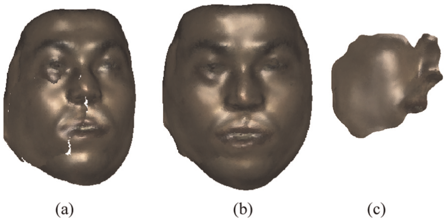
In clinical application, however, if the time interval between removal surgery and prosthesis operation is too long, the patient’s oral soft tissue may have a significant shift caused by the traction of defect (Figure 1). Since the deformation may affect the final results of prosthetic restoration, some measures need to be taken to correct the local deformation of the oral soft tissue before making the prosthetic modelling. Some commercial two-dimensional (2D) simulation packages are available, such as the AlterImage (Cosmetic Surgery Simulation system) to manipulate 2D images with morphing operators. 4 However, the human face is a complex three-dimensional (3D) object, and several systems for manipulating 3D faces have been studied. Z Kavagiou et al. 5 chose a free-form deformation technique to perform a controlled deformation of the nose and its surrounding tissue. The drawback of this method is that the user had to manipulate the control mesh rather than the object surface. T Wu et al. 6 proposed finite element method (FEM) to simulate nonlinear soft tissue deformations. Finite element analysis 7 is an innovation in biomedical research method; however, inaccurate material properties (such as Young’s modulus of elasticity and yield strength, Poisson’s ratio and density) may yield even totally misguiding results. J-X Wang et al. 8 also drove the 3D deformation of the nose shape for rhinoplasty in real time by the Laplacian surface deformation method. SH Liao et al. 9 implemented the gradient-based volumetric deformation approach, resulting similar non-smooth deformation in the ridge of the nose.
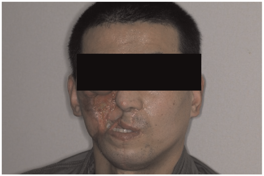
Patient’s oral soft tissue has a significant deformation.
In maxillofacial prosthesis modelling, the healthy facial side can be mirrored onto the deformities at the mid-facial plane to construct the maxillofacial prosthesis. The quality of the mid-facial plane is, therefore, very important. To address these problems, some new methods have been developed. As for the healthy face, one method is principal component analysis (PCA), a method based on the centre of mass;10,11 another approach uses iterative closest point (ICP) optimization proposed by Benz et al. 12 and Hartmann et al. 13 However, for faces with defects, the situation is different. When PCA is used, the drift in the centre of gravity may cause severe drift in the mid-facial plane, while in the case of ICP, some poorly corresponding point pairs may reduce the quality of the mid-facial plane. X Li et al. 14 defined a local shape signature consisting of the principle curvature and the shape diameter function to obtain reliable symmetry detection of damaged skulls. In 2013, Sun et al. 15 put forward an improved ICP algorithm for orbital prosthesis modelling. This algorithm is based on the M-estimator, which can ignore outliers in the optimization and detect incorrect symmetries.
Although a lot of work have been done in maxillofacial prosthesis modelling, to the best of our knowledge, how to deal with the deformation and how to improve the validation of symmetry point pairs in the case of large defects were rarely been reported. Therefore, in our article, for incomplete maxillofacial data with local deformed symmetrical features, a Laplace algorithm with rotation invariants was put forward to recover the local deformation, and an improved ICP algorithm based on extended Gaussian image and M-estimator was proposed, making the outer point having almost no effect on the minimum process.
Computational methods and theory
A 40-year-old man who had left maxillofacial defect was scheduled to receive a maxillofacial prosthesis. The complete workflow of the process using deformation corrected workflow included the following steps (Figure 2):
Step 1. Reverse engineering was conducted based on 3D areal-structured light scanner of defective regions of the patient’s face.
Step 2. Use CAD to make the custom-made prostheses. For incomplete maxillofacial data with local deformed symmetrical features, first, the local deformation need to be recovered, then the healthy facial side was mirrored onto the defect region by the mid-facial plane. After blending, a segmentation operation along the defect boundary was used to develop the maxillofacial prosthesis model.
Step 3. Rapid prototyping (RP) of the prosthesis made by plastic material was carried out by stereo lithography apparatus (SLA).
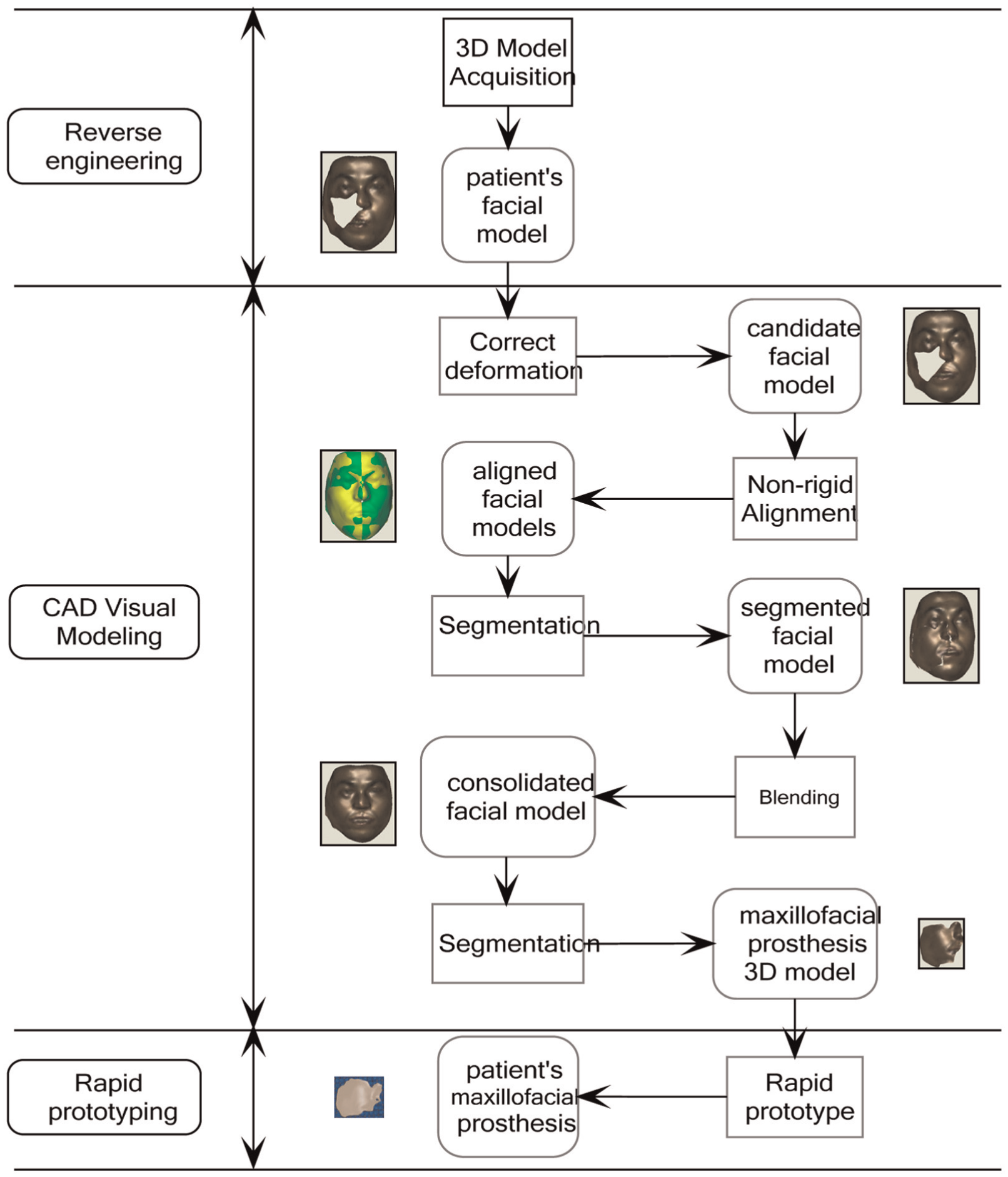
Deformation corrected workflow for maxillofacial prosthesis fabrication.
Reverse engineering
A 3D optical measurement system based on fringe projection was developed for maxillofacial prosthesis as shown in Figure 3(a). This system consisted of two measurement sensors, each of which was composed of a slide projector and a charge-coupled device (CCD) camera. The slide projector utilized a physical grating with desired grey code and phase shift fringe patterns. The phase shift fringe patterns were fabricated with extremely high precision by the photolithography technology. In order to translate the physical grating for the shifting between the fringe patterns, an inner moving mechanism was used. The basic parameters of the measurement system are shown in Table 1. While scanning, the patient is asked to sit in front of the scanner and looks straight ahead, keeping his head motionless throughout the examination. Next, the scanner acquires data of patient face as a series of images from two different directions. Then, after decoding, the images can be translated as two point sets. The pre-process techniques such as data cleaning, reduction and merging need to be used. Finally, a complete point set of the patient’s face can be seen in our software TdosFaceMMK (Figure 3(b)).

3D acquisition of a patient’s facial point set: (a) measurement system and (b) patient’s facial point set.
Main specifications of 3D optical measurement system.

3D: three-dimensional.
CAD virtual modelling
Correction of local deformation
In order to correct the local deformation on the mouth region from Figure 3(b), the local deformation correction algorithm was proposed as shown in Figure 4. The steps involved are as follows:
1. Inputting the original mesh

The workflow of local deformation correction algorithm.
Let the original mesh M be described by a pair
2. Defining the local deformation
The points of ‘handle’ part were forced to move under the user interaction, the points in the region of interest (ROI)
3. Computing the transformation
If an appropriate transformation

where H is the ROI. In order to ensure that equation (1) is a linear equation,
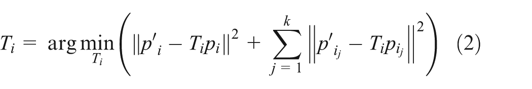
where

4. Getting the corrected mesh
The editing process is illustrated in Figure 5. The ROI for editing was defined as shown in Figure 5(a) and the handle inside the ROI was also defined. By manipulating a handle, a set of vertices inside the ROI can be moved, rotated and scaled. The reconstruction of the sub-mesh required solving the linear least-squares system as described in equation (1). Then, the facial surface was reconstructed with respect to the relocation of the handle as shown in Figure 5(b). Note that the details of the surface were preserved.

Illustration of the local deformation corrected operator: (a) the region of interest for edit and (b) the reconstructed facial surface.
Use of the symmetry operator
As mentioned in the introduction, to construct the maxillofacial prosthesis, it is necessary to first compute the symmetry plane of the patient’s facial mesh. The steps are as follows.
1. Defining the reflected mesh
Along the right sub-plane of the bounding box of the facial mesh S, flipping the mesh S can produce the reflected mesh
2. Making rough alignment

Illustration of the symmetry operator: (a) rough alignment of patient’s facial mesh and reflected mesh, (b) Gaussian image of plane curve, (c) point cloud, (d) extend Gaussian image of point cloud, (e) fine alignment using an improved ICP algorithm and (f) symmetry plane of the patient’s facial mesh.
Two views (Figure 6(a)) were used to display the patient’s facial mesh S and the reflected mesh
3. Conducting symmetry detection
An improved ICP algorithm based on the extended Gaussian image and the M-estimator was used to find the necessary symmetric information. This algorithm began by matching each reflected point of the reflected mesh

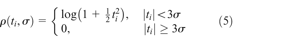
When the residuals are greater than three times
Construction of the maxillofacial prosthesis model
Along the mid-facial plane, the healthy maxillofacial region was mirrored onto the defect area as shown in Figure 7(a). A complete facial model can be produced by blending between the mirrored part and surrounding tissues as shown in Figure 7(b): first, the boundary of the mirrored part can be adjusted to attach to the surrounding tissues with tangent continuity; then, the gap between the adjusted mirrored part and the surrounding tissues can be triangulated; finally, the smooth operation can be done on the triangulated mesh by umbrella operator. 19 As shown in Figure 7(c), the maxillofacial prosthesis model can be obtained using segmentation along the boundary of the defect region.
Data process for obtaining the maxillofacial prosthesis model: (a) mirroring the healthy facial side onto the defect region, (b) blending between the mirrored part and surrounding tissues and (c) segmentation for the maxillofacial prosthesis model.
Result
As shown in Table 2, before correcting the deformation, parameter A (the distance between the centre of the mouth and the external naris distance) in the vertical direction was 22.0 mm, parameter B (the distance between the centre of the patient’s mouth and the symmetry plane) in the horizontal direction was 5.3 mm and parameter C (the distance from the centre of the mouth to left corner of the patient’s mouth) was only 17.6 mm. After correcting the distortion of the mouth, parameter A was 21.6 mm, almost the same as before; parameters B and C were, respectively, adjusted for 0.1 and 29.5 mm. Parameter C was the half value of the width of the mouth which was 59 mm, achieving a normal mouth length. The results of the evaluation showed that the maxillofacial model was in line with the aesthetic requirements.
Comparison of measurement results of correcting the deformation.

A: the distance between the centre of the mouth and the external naris distance; B: the distance between the centre of the patient’s mouth and the symmetry plane; C: the distance from the centre of the mouth to left corner of the patient’s mouth.
Then, the data of the 3D maxillofacial prosthesis model can then be exported to STereoLithography (STL) format, which was accepted by the RP system. SLA was used to fabricate a maxillofacial prototype (as shown in Figure 8) that can then be used as a casting pattern to form a silicon rubber mould. After pouring silicone rubber material into the cavity and waiting for a certain time, mould can be opened to take out the desired maxillofacial prosthesis.

Maxillofacial prosthesis model and its rapid prototype.
Discussion
In this article, we demonstrated the Laplace approach of correcting the deformation, showing that the editing operations can change the shape while respecting the structural geometric detail.
To further verify the ability to preserve surface geometric detail, first, the additional qualitative and quantitative experiments were conducted as shown in Figure 9 and Table 3. In Figure 9(a), the change in surface geometric detail was examined by aligning the patient’s maxillofacial models before and after the editing operations. The main deformation was concentrated on the region of the mouth illustrated by blue colour. In addition, 12 points were taken from the surrounding area of the region of the mouth in Figure 9(b), and the deviation values between the patient’s data set before and after deformation can be seen in Table 3. The maximum distance deviation from Table 3 is 0.1910 mm. That means the surrounding areas were almost not be affected.
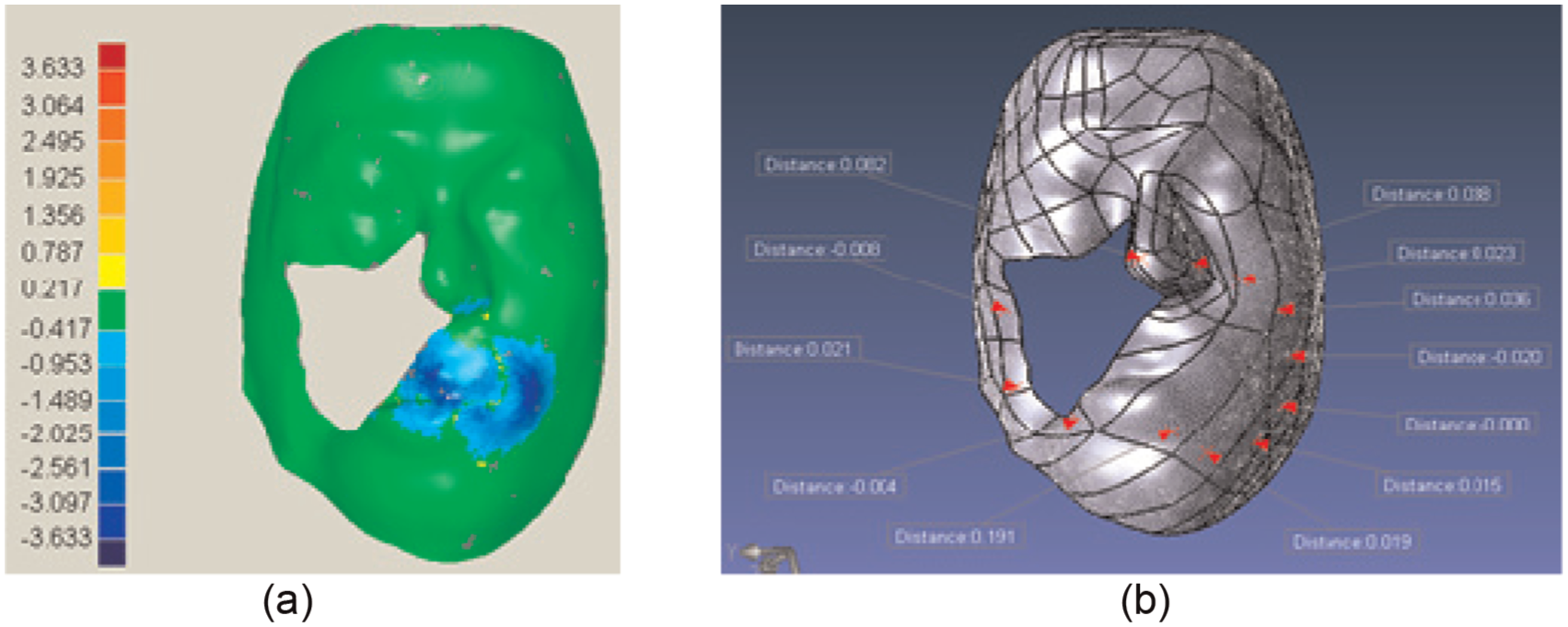
The evaluation of the ability to preserve surface geometric detail: (a) qualitative test and (b) quantitative test.
The deviation between the patient’s data set before and after deformation.

The significance of bold values (0.1910) is the maximum distance deviation from Table 3.
Second, the M-estimation ICP-based iterative algorithm integrated with the extended Gaussian image was proposed. To further test the effect of the algorithm, an additional experiment was conducted. Since the patient’s facial model has no prior data from the mid-facial plane, synthetic data were used to simulate the case of a large area facial defect. During these experiments, the 3D model Deny of INRIA 20 was used to represent a healthy face, as shown in Figure 10(a). The triangle number of the normal facial model is 8252 and its file space is 255 kB. Figure 10(b) shows the model of a large facial defect, with a triangle number of 6972 (84.5%) and a file space of 225 kB. Two views (Figure 10(b) and (c)) were used to display the patient’s facial mesh and the reflected mesh separately. With the similar shapes on the two extended Gaussian images (Figure 10(C) and (D)), the rough alignment of the patient’s facial mesh and the reflected mesh can be achieved automatically, avoiding any manual rough alignment or the use of landmarks. Due to a quality initialization for fine alignment (Figure 10(e)), Figure 10(f) shows the best results: the light blue region was well distributed, which means that the range of the overlapped distance of the two images is 0–0.5 mm in the normal direction.
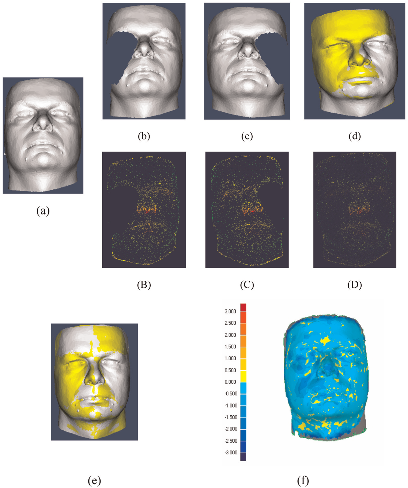
Large defect maxillofacial model and the alignment experiment: (a) normal facial model; (b) large defect facial mesh; (c) reflected mesh; (d) rough alignment of (b) and (c); (B) extend Gaussian image of (b); (C) extend Gaussian image of (c); (D) extend Gaussian image of (d); (e) fine alignment of (b) and (c); (f) colour map between (e) and (a).
Compared to traditional 2D image-based simulation tools, the 3D simulation approach is more intuitive and straightforward to use. Compared to previous 3D simulation tools, such as gradient-based method and FEM, the Laplacian-based method can solve a normal system of order 2, while gradient-based method, as well as FEM, can only deal with the system of order 1, and the approach can provide more smooth deformation, which is important for the use of ROI with very sparse handle vertices to drive deformation, thus more suitable for the reverse simulation configuration of maxillofacial model. In addition, the system can design the patient-specific prosthesis model easily according to the simulated post-operative appearance, which is one of the most common facial surgeries. The designed prosthesis model can also be exported to some RP equipment to generate the specific prosthesis directly.
Conclusion
In this article, based on the improved Laplace and ICP-based iterative algorithms, a deformation corrected workflow for maxillofacial prosthesis fabrication was proposed. For incomplete maxillofacial data with local deformed symmetrical features, the Laplace algorithm with rotation invariants was demonstrated, showing that the operations can recover the local deformation while preserving the surface geometric detail. To construct the maxillofacial prosthesis, it is necessary to first compute the symmetry plane; the M-estimation ICP-based iterative algorithm was applied to integrate with the extended Gaussian image. The rough alignment was performed automatically with the similar shapes on the two extended Gaussian images, providing a quality initialization for fine alignment and avoiding any manual rough alignment or the use of landmarks. And the M-estimation ICP-based iterative algorithm was used for the fine alignment, making the outer point having almost no effect on the minimum process. Case study confirmed that this workflow is attractive and has potential to design the desired maxillofacial prosthesis for correcting the deformed oral soft tissue. Although this deformation corrected workflow has great potential for improving the development of maxillofacial prosthesis modelling software, much work is still required to meet the requirement of facial prosthesis design and fabrication. First, the deformation method is not directly used for tissue cutting, although not required in support current simulation system. Second, it is essentially a geometric method; some improvement will be made in taking physical material into consideration. Third, the integration of the finite element analysis and the geometric method will be considered to facilitate highly realistic maxillofacial prostheses modelling. Finally, since how to fill the void in the face is important for the prosthesis design, in the following work, we will also focus on it.
Footnotes
Academic Editor: Nicolas Garcia-Aracil
Declaration of conflicting interests
The author(s) declared no potential conflicts of interest with respect to the research, authorship, and/or publication of this article.
Funding
The author(s) disclosed receipt of the following financial support for the research, authorship, and/or publication of this article: This work was supported by National Natural Science Foundation of China (Grant Nos 51475409 and 51375427), Jiangsu Province Basic Research Program Natural Science Foundation (Grant Nos BK20141277 and BK20131232), Yangzhou University of Science and Technology Cooperation Program Funds (No. YZ2016244) and 2016 Six Talent Peaks Project in Jiangsu Province (No. JXQC-030).