
Abstract
This article collects the development of a frontal composite structure for electric light vehicles (concretely within L7e European category), which has been required to fulfil energy absorption capabilities for pedestrian protection. An initial design made of a composite sandwich structure (glass fibre skins with polyvinyl chloride foam core) was proposed and a prototype was manufactured and tested against impact. Then, a numerical model was created and the impact test was simulated by the finite element method. After adjusting the numerical model to the real performance of the component, the initial material configuration of the sandwich composite was optimized according to design objectives involving safety, current regulations and repairability.
Introduction
Since 1970s, experimental, numerical and field data analyses have shown the relevance of vehicle design on pedestrian injuries. As a result of this, during the last two decades, the improvement of pedestrian safety has become an important design factor in modern automotive industry. 1 When a vehicle-to-pedestrian crash occurs, the level of injuries on pedestrians is determined by numerous factors such as the external shape and dimensions of the vehicle, its velocity during the impact, the areas of contact with the pedestrian, the energy absorption capability, the deformation limits and materials involved at each area, as well as by the pedestrian position, size and age.
The Global Technical Regulation No. 9 from the United Nations ‘Pedestrian Safety’ collects the test procedures for assessing the pedestrian frontal protection in current light vehicles such as passenger cars, sport utility vehicles (SUV), light trucks and other light commercial vehicles; however, their application to heavy vehicles or to very small and light vehicles could be of limited value and may not be technically appropriate. 2
In this respect, the APROSYS European project3,4 provided solutions and gave design recommendations for reducing the severity of injuries of vulnerable road users (VRUs) in head-on collisions against heavy vehicles and passenger cars. New assessment methods for VRU’s tests were analysed and a heavy vehicle aggressivity index (HVAI) was defined, including three factors: run over, structural and field of view. A frontal protection component for heavy vehicles was analysed in order to prevent pedestrians from being run over in case of impact against the vehicle, as well as to achieve a reduced severity for the secondary impact that could take place when the pedestrian is projected forward. Energy absorption capability at the front of the vehicle was considered essential not only for reducing the severity of the first impact, but also of the secondary impacts, appearing due to the contact with the road or the ground (after striking the vehicle and bouncing). Badea-Romero and Lenard 5 determined that head injuries or impacts occurred in 110 out of 205 accident cases analysed that had taken place in the United Kingdom, and that the first impact with the vehicle was associated with a majority of more serious casualties.
Since the vehicle’s structural behaviour in frontal impacts is crucial for reducing VRU’s injuries severity, recent research efforts are being implemented in this direction. For instance, Davies 6 studied eight cars manufactured between 2006 and 2010 and concluded that stiffnesses of the bonnet and front bumper in modern cars are being reduced due to the influence of European New Car Assessment Program (Euro NCAP) pedestrian tests. Lee et al. 7 carried out a design optimization of frontal structures such as the energy absorber, the lower bumper stiffener and the hood angle in order to reduce the injury risk, using a numerical model of the flexible pedestrian legform impactor (Flex-PL). Nie et al. 8 developed a parametric vehicle front-end model in order to predict human lower limb injuries from geometry and stiffness variables by means of impact simulations with a pedestrian human body model. Teng and Ngo9,10 analysed how structural design parameters such as the use of reinforcement structures and the bonnet thickness affect acceleration during head-to-bonnet impacts and help to optimize the head’s acceleration pulse. Huang et al.11,12 evaluated geometry and stiffness for designing car bumper systems and front ends, in the first case to reduce leg injuries and in the second case to estimate the necessary energy absorption space in pedestrian lower limb impacts. Liu 13 studied the frontal impact behaviour in a truck chassis and the optimization of thin-walled energy absorbers.14,15 Liu and Day 16 also carried out impact tests and computer simulations on a bumper system for vehicles.
As stated by Fredriksson, 17 smaller cars may need to be stiffer due to the short energy absorption distance in frontal crashes. This author also points out that in contrast to standard internal combustion engine cars, which have the rigid engine at the front, electric cars offer the possibility of locating the drivetrain in other parts of the car body. Therefore, new electric vehicle technologies make possible a different operation layout in electric engine vehicles compared with the conventional layout used in internal combustion engine vehicles. For instance, the emergence of in-wheel electric engines opens up new possibilities in the internal layout since more free space is available at the front of the vehicle.
As a result of this, electric vehicles could be designed with different geometries and stiffnesses at their front end, and more research is needed to optimize pedestrian protection in these car types. Additionally, the fast evolution, that electric vehicles are experiencing nowadays, makes necessary to develop new approaches to guarantee or even optimize pedestrian passive safety in new designs.
Objective
The research described in this article is focussed on the design and optimization of a frontal structure for electric vehicles which must be able to perform friendly with VRU in case of accident. Concretely, it was applied to the L7e European vehicle category, which covers a type of vehicles that are also referred to as ‘heavy quadricycles’. L7e vehicles are defined as motor vehicles with four wheels whose mass in running order is not more than 450 kg for transport of passengers, or 600 kg when the vehicle is intended for carrying goods. In the case of electric vehicles, the mass of batteries is not included in this limit and a maximum net engine power of 15 kW is specified.18,19
Although pedestrian safety measures are currently being implemented in some types of vehicles, no regulation related to pedestrian protection in L7e category vehicles exists yet and no test procedure has been defined to assess their performance in relation to this specific aspect. On one hand, as constructive restrictions are not as severe as in other vehicle categories, this gives more freedom to incorporate innovative design solutions. On the other hand, as new technologies are continuously emerging in the field of electric vehicles, there is now a good opportunity for exploring pedestrian protection from the perspective of new vehicular design approaches. By this way, the main objective of this article is to reduce the number of both fatal and serious injuries in accidents where pedestrians, cyclist or motorcyclist impact against an L7e category electric vehicle. A frontal structure made of composite material in different configurations has been dynamically tested both virtually and experimentally. By means of experimental validation of a finite element (FE) numerical model, it was be possible to propose numerically an optimum design for achieving an adequate energy absorption capability with a reasonable agreement between deceleration and deformation values.
Low decelerations during an impact imply reduced injury level for VRU. However, this situation may require large deformations and high vehicle damages, which would consequently lead to high repairability costs. Therefore, another design objective was to optimize both the final plastic strains and the maximum displacement reached during the impact process. An economical repairability and maintenance of the component are desired and damages that may take place, for instance, due to low velocity impacts against other vehicles in urban areas should also be reduced. At the same time, vehicle weight reduction was also a key design objective due to its high influence in energy consumption and to meet the weight criteria for the vehicle category.
Frontal structure’s design and initial prototype
The initial task was to design the exterior shape of the frontal structure, taking into account the existing requirements for the vehicle category selected. As the most external layer of the vehicle at the front, this component is the first part of the vehicle that would contact with objects or VRUs in case of frontal collision. Figure 1 shows the three-dimensional (3D) model of the frontal structure with its external dimensions.

Geometric model of the frontal structure (dimensions in millimetre).
On one hand, its height and position in relation to the vehicle were defined according to the driver’s field of vision required by Directive 77/649/EEC, 20 as shown in Figure 2.

Frontal structure’s position in the vehicle (dimensions in millimetre).
On the other hand, the geometry tried to avoid a direct impact of the head of a Hybrid III 50th male dummy against the cabin or the windscreen. In this regard, considering the dummy positioned laterally centred in front of the vehicle, the head impact position was approximated as if the centre of rotation for the dummy motion was the knee joint that first impacted the frontal add-on (Figure 3).

Hybrid III 50th percentile male dummy positioned laterally in front of the vehicle. Estimation of head impact position for a centre of rotation at knee joint’s height.
The APROSYS European project’s extensive considerations concerning the deflection of the pedestrian to one side of the road in case of a pedestrian frontal impact were also taken into account and, in order to achieve this behaviour and to avoid run over situations, a rounded circular shape was adopted in the contact area with the legs. 21
Directive 2005/66/EC 22 established a maximum total mass of 18 kg for a pedestrian frontal protection system, including all brackets and fixings to the vehicle, and it has not to exceed 1.2% of the mass of the vehicle. In order to satisfy these requirements, it was proposed that an optimum frontal protection system should be designed with light materials such as composite materials and polymers. At the same time, an adequate combination of materials could optimize the stiffness of the frontal components involved in the impact. The authors such as Teng et al. 23 have proposed sandwich hood structures for reducing pedestrian head injuries, which included carbon fibre–reinforced polycarbonate, carbon fibre–reinforced foam and aluminium-reinforced polycarbonate, and checked their stiffness and energy absorption capability. Also in this sense, Belingardi et al. 24 studied with FE simulations the weight reduction and redesign of several car bonnets, using innovative materials such as hybrid metal/plastic solutions, focussing on the impact of the bonnet against a pedestrian head. Once that the torsional and bending stiffness and the denting distance were checked, pedestrian head impact simulations were performed and results showed that the introduction of innovative material solutions can improve both weight reduction and pedestrian head safety.
The manufacture of this frontal structure in composite materials was finally considered an adequate solution for satisfying the technical requirements of energy absorption, VRU safety and weight reduction in the component. Then, an initial prototype of the frontal structure was constructed, concretely a composite sandwich structure comprising the following layers, from the inner side to the outer:
A 1.75-mm-thick layer of glass mat–fabric with density of 650 g/m2. Matrix in polyester resin.
A 20-mm-thick foam core made of polyvinyl chloride (PVC) with density of 60 kg/m3.
A 1.75-mm-thick layer of glass mat–fabric with density of 650 g/m2. Matrix in polyester resin.
A 0.8-mm-thick layer of emulsion-glass chopped strand mat (E-CSM) with density 300 g/m2. Matrix in polyester resin.
A 0.7-mm-thick outer layer of transparent polyester gelcoat.
The initial prototype (Figure 4) made possible to analyse the behaviour against impact and the energy absorption capability for this chosen material configuration.
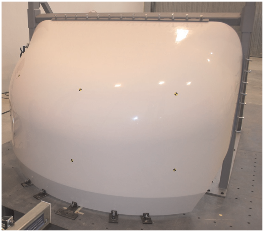
Initial prototype of the frontal structure assembled to the test platform.
The total thickness of the component was 25 mm, from them being 20 mm for the PVC foam core and 5 mm for the skins of glass fibre and the external gelcoat. Table 1 shows approximately the mass distribution for this initial configuration, where a total mass of 31.4 kg was obtained.
Mass distribution in the initial prototype of frontal structure.
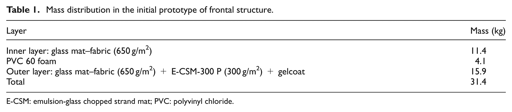
E-CSM: emulsion-glass chopped strand mat; PVC: polyvinyl chloride.
In the first place, the tooling manufacturing for this prototype consisted of a polystyrene plug coated with low-shrinkage epoxy paste as a positive structure of the finished product with additional flanges. On the second place, it was necessary a negative structure, which was a mould made of laminate material comprising glass mat and glass fabric combined with vinyl ester–polyester resin. Although both were prepared for an infusion process, it is possible to use them for different laminate technologies such as ‘vacuum bag’ or ‘resin transfer moulding’. According to the composite manufacturer Bella, this plug and mould method is specifically used for the manufacture of large volume productions where several hundred demoulding operations are planned. Figure 5 shows the 3D design of the plug and the mould.

Plug with flanges (left) and mould with flanges (right).
FE model of the frontal structure
On the basis of the initial design and a 3D geometrical model, an FE model of the frontal structure was created by means of the combination of the FE software programs Msc-Patran and Ls-Dyna Prepost. This mesh model consisted of 60,075 four-node tetrahedral solid elements for modelling the PVC foam core and 33,302 three-node shell element for modelling the inner and outer fibreglass skins, adding up to a total number of 93,377 elements. In this case, taking into account the general dimensions of the component, a mesh size of 20 mm was considered adequate for modelling the shape of the component appropriately, as well as for simulating and optimizing it with reasonable computational costs. The shell elements in the skins were joined to the solid elements forming the core by means of coincident shared nodes located at their exterior faces. Figure 6 shows the complete mesh model for the frontal structure.
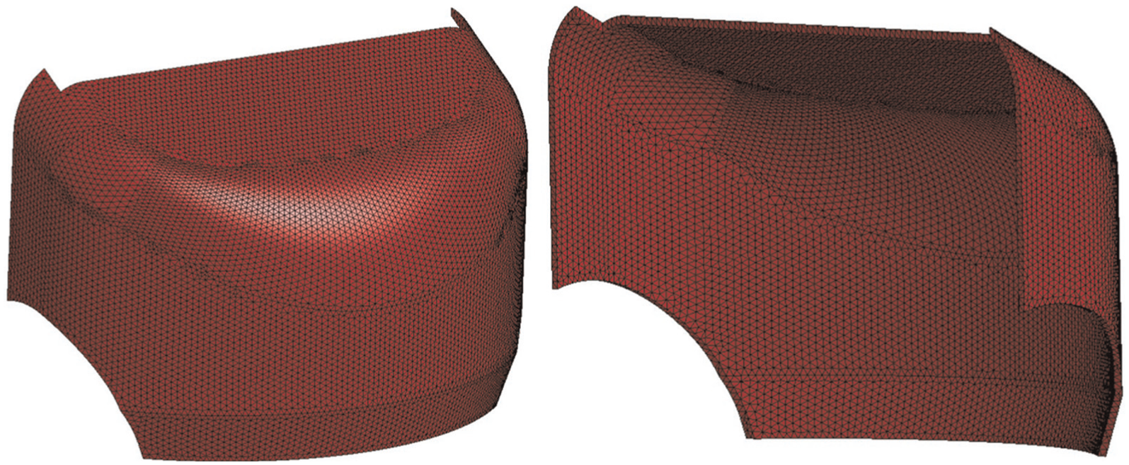
Finite element model of the frontal structure.
Boundary conditions were set considering the test configuration (Figure 4); concretely, all nodes at the top, bottom, left and right edges of the frontal component were fully constrained in displacement.
In order to simulate correctly the mechanical behaviour of the composite sandwich, it was necessary to test specimens of each material comprising it to obtain their corresponding individual mechanical properties. Then, these properties were introduced to appropriate material models in Ls-Dyna so as to assign the corresponding properties to each part comprising the component.
Table 2 shows the values obtained for E-CSM emulsion fiberglass mat of 300 g/m2 and glass mat–fabric of 650 g/m2, in both cases together with a polyester resin matrix. Apart from these values, the shear modulus was also obtained resulting in 0.68 GPa for the first one and 1.13 GPa for the second one. The uncertainties estimated for the mean values obtained are also included in Table 2. 25
Mechanical properties obtained from testing: CSM emulsion fibreglass mat of 300 g/m2 and glass mat–fabric of 650 g/m2, both with polyester matrix. 26

CSM: chopped strand mat.
Concerning the exterior layer of gelcoat, the properties considered were extracted from the technical information from the manufacturer: 27
Density = 1.15 g/cm3;
Tensile strength = 75 MPa;
Young modulus = 3400 MPa.
The characterization of the glass fibre skins in Ls-Dyna software was carried out by means of the material model MAT_ENHANCED_COMPOSITE_DAMAGE (054/055), where all the layers of the different materials were defined according to their corresponding mechanical properties and Tsai Wu criterion for matrix failure. 28 Then, two composite parts were created for the inner and outer skins by means of the command PART_COMPOSITE_CONTACT, selecting the thickness and material for each layer comprising the skins. The mechanical properties considered for the PVC foam were obtained from the data for ‘DIAB Klegecell® R 60 Rigid, Closed Cell PVC Foam Core Material’ recommended for high-strength, low-weight composite structures in vehicles: 29
Density = 60 kg/m3;
Compressive modulus, E = 76.98 MPa;
Poisson ratio = 0.32;
Tension cut-off stress = 2.5 MPa.
The PVC foam’s stress–strain curve is defined in Figure 7, which was obtained from uniaxial compression tests by Tita and Caliri. 30

Stress–strain curve considered for PVC foam with density of 60 kg/m3.
Finally, the foam core was characterized in Ls-Dyna by means of a MAT_LOW_DENSITY_FOAM (057) material model, including the following parameters:
Hysteresis unloading factor = 0.5;
Shape factor for unloading = 5;
Viscous coefficient for damping effects = 0.5.
Impact tests and numerical–experimental correlation
The next step was to define the test procedure for assessing the energy absorption capability of the frontal structure in case of impact against a pedestrian or other VRU. Conventional car tests with headform impactor, and lower and upper legform impactors were developed mainly to prevent pedestrians from impacting those excessively rigid parts such as the engine block and other components located at the front of the vehicle. When this occurs, the high decelerations and rigid contacts will lead to high severity injuries or even to fatalities and this situation is not desirable. Therefore, the great achievement of new regulations is that nowadays more and more pedestrian friendly designs are being implemented to new cars. Evidently, the emergence of new electric vehicles, which can be designed with a completely different configuration of engine components at the front, will require the definition of new tests and regulations adapted to them. This research reflects this situation as, on one hand, L7e type vehicles have not yet a specific regulation concerning passive safety for VRU protection and, on the other hand, the implementation of in-wheel motors, leaving more free space at the front once the engine block is substituted, can lead to a totally different point of view in relation to pedestrian safety tests.
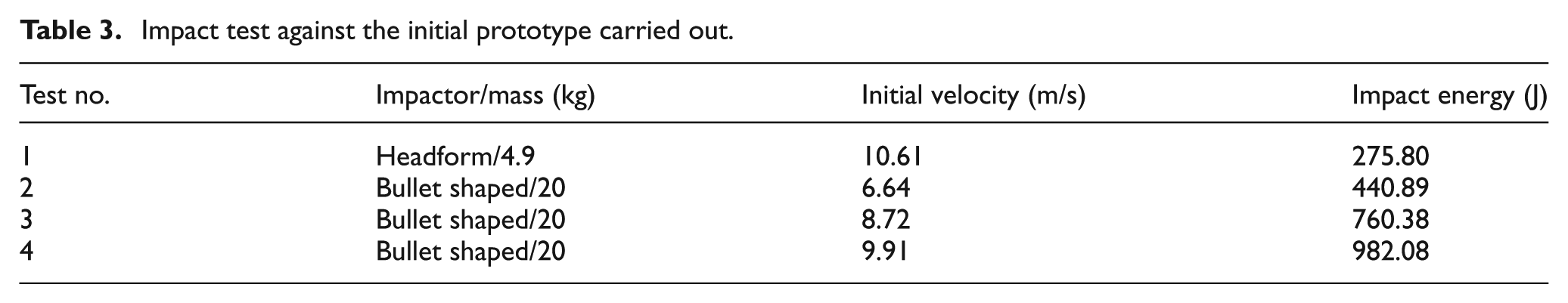
As a result of this, different levels of impact energy were applied in preliminary impact tests against the initial prototype, using a 4.9 kg steel headform impactor as well as a 20 kg steel bullet-shaped impactor, which is shown in Figure 8. This second impactor comprises a semi-spherical part (diameter: 165 mm) with an accelerometer inserted inside and a cylindrical part bolted to its planar area. The complete impactor has the option of weighing 16 or 20 kg depending on the size of this cylindrical part and it was specifically manufactured for carrying out impact tests in an Anthropomorphic Form Launcher (available at University of Zaragoza facilities in Motorland, Teruel, Spain). It is made of St 37 steel and is also bolted to a special tool for adjusting the impactor to the launcher by means of several breakable plastic pins. On the other hand, the lighter 4.9 kg steel headform impactor is periodically used in the calibration tasks of the launcher. A numerical model of this impactor was also created by means of eight-node hexahedron solid elements (Figure 14). The same external shape, material and total mass were used in the impactor’s numerical model and an accelerometer property (element seatbelt accelerometer in Ls-Dyna) was assigned to a rigid shell element placed at its centre.

Bullet-shaped impactor from University of Zaragoza. 20-kg option.
The following impact tests were carried out, launching the impactors with a different initial velocity for gradually increasing the impact energy at each case. Impact points were selected at a similar height at the middle transversal plane and the same prototype was used in all the tests. While test no. 1 with the lowest impact energy resulted in an elastic behaviour of the prototype and no damage was produced, test no. 4 with the highest energy level led to the appearance of plastic strains and several cracks in the prototype (Table 3).
Impact test against the initial prototype carried out.
Figures 9–12 show two frames of each test, the first one with the maximum strain reached and the second one with the impactor bouncing after hitting the prototype.
Impact test no. 1.

Impact test no. 2.

Impact test no. 3.
Impact test no. 4.
The same prototype was used in these tests, so, in order to avoid the influence of deformations reached in previous tests and taking into account that test no. 1 produced no damage, the experimental values obtained in test no. 2 were used for carrying on a numerical–experimental correlation analysis. In this case, the 20-kg impactor was launched at 6.64 m/s2, reaching a total kinetic energy of 440.89 J, and directed to the centre of the prototype at a height of approximately 390 mm from the base, as shown in Figure 13. Although test nos 3 and 4 accumulated the influence of plastic strains and damages generated in previous tests, the maximum displacement results were measured and also numerically correlated for these tests. As can be observed in Figure 4, the prototype of the frontal component was fixed and assembled to the test platform using an additional metallic frame in all the tests.

Anthropomorphic Form Launcher (left) and impactor position before the test (right).
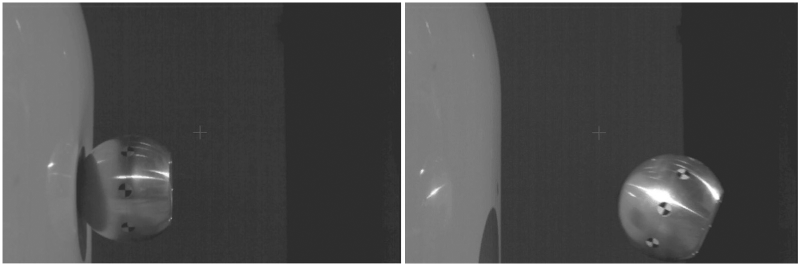
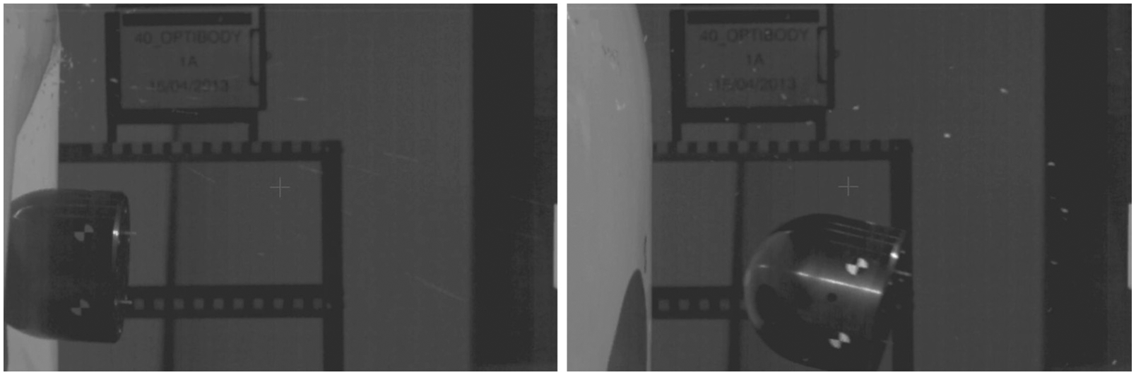
It was possible to capture the impact moment by means of a high-speed camera recording at 1000 frames per second (fps). Two moments were the most important: the contact of the impactor with the frontal structure and the moment at which the displacement and deformation reached its maximum. Figure 14 shows the latter situation corresponding to test no. 2, in both the experimental test and the simulation in Ls-Dyna. The maximum displacement obtained in the component was approximately 50.27 mm in the test and 57.45 mm in the numerical simulation. Table 4 collects the results in maximum displacement for test nos 2, 3 and 4 and their numerical simulations, which showed a high correlation.

Moment of maximum deformation in the test and the simulation.
Maximum displacement reached in tests and simulations.

Figure 15 shows the deceleration values obtained in test no. 2 and its simulation. While the maximum value obtained in the experimental test was 67.76 m/s2, the numerical simulation produced a maximum deceleration value of 70.90 m/s2. However, while the experimental curve had oscillations ranging between 50 and 70 g’s, the numerical curve showed a smoother behaviour. Apart from this, it could be observed that both deceleration curves presented quite a similar aspect, with a total pulse duration of 30 ms approximately. The obtained numerical–experimental correlation in terms of deformation and deceleration was considered adequate for carrying out the subsequent optimization.
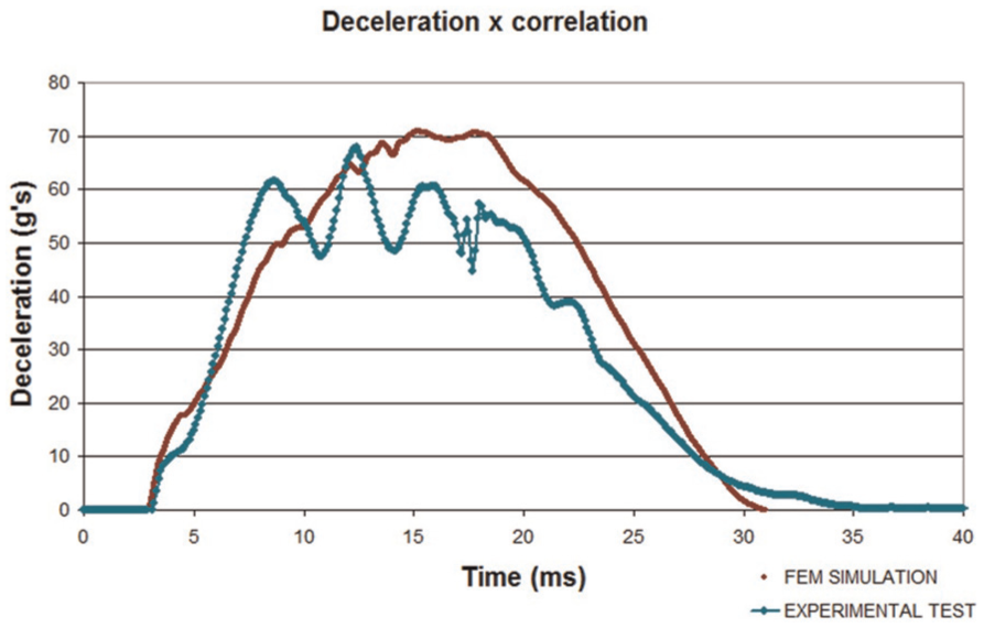
Numerical–experimental correlation for the deceleration in the x direction obtained in test no. 2 at the impactor’s accelerometer.
Numerical optimization of the initial design
Material configurations and impact positions analysed
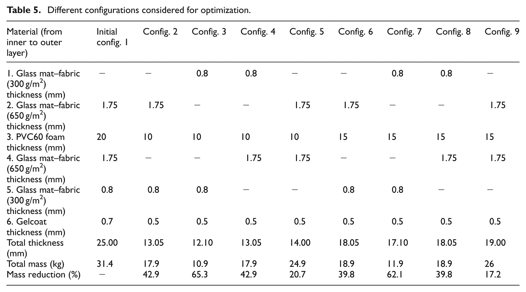
The validated numerical model was then used to carry out a numerical optimization of the frontal add-on in the next step. Moreover, the total mass of the initial prototype was 31.4 kg, a value much higher than 18 kg, 22 so a lighter configuration with an optimized behaviour was necessary. Eight cases were proposed; on one hand, different configurations with the same composite material layers were modelled. On the other hand, changes in the foam core’s thickness were also checked, lowering its value from 20 to 10 mm (configurations 2–5) and 15 mm (configurations 6–9).Table 5 shows the thicknesses considered in these eight cases and compares the total mass of the initial prototype with the estimated total mass for each case. It can be observed that configurations 2 and 4 are similar, in the same way as configurations 6 and 8, but with their glass fibre layers ordered inversely.
Different configurations considered for optimization.
In order to compare these different configurations, the following four impact positions were considered in the simulations, with the impactor located centred at the middle longitudinal plane of the component. All of them were based on existing tests for pedestrian protection in M1 and N1 European vehicle categories:
Wrap around distance (WAD) = 625 mm and initial velocity = 9.08 m/s. Similar energy level as required in lower legform test, E1 = 825.51 J and impactor launched horizontally.
WAD = 1000 mm and initial velocity = 7.65 m/s. Similar energy level as required in upper legform test, E2 = 585.24 J and angle of impact 50° to the ground reference level.
WAD = 1500 mm and initial velocity = 5.43 m/s. Similar energy level as required in adult headform test, E3 = 295.70 J and angle of impact 65° to the ground reference level.
WAD = 1700 mm and initial velocity = 5.43 m/s. Similar energy level required in adult headform test = 295.70 J and angle of impact 65° to the ground reference level.
Figure 16 shows the four impact positions analysed.

Transversal section view with the impact positions considered for the optimization.
Optimization constraints and objectives
In the first place, it was considered that an optimized design should provide an optimum safety to pedestrians, adequately withstanding the different impact cases set out. Moreover, it should achieve a mass reduction of the product as well as lower the manufacture and repairability costs. It has to be noted that the optimization of these parameters is contradictory in the sense that a high deformation can be desirable in order to decrease the deceleration values in the pedestrian, but at the same time not desirable in terms of repairability costs. Once the numerical simulations were analysed, the following variables were taken into account in the optimization procedure:
Mass reduction;
Maximum deceleration reached in the impactor’s accelerometer;
Head injury criterion (HIC) 15;
Energy absorption capability of the component;
Maximum deformation, material failure and damage level.
Concerning mass reduction, a maximum total mass value of 18 kg was considered; material configurations nos 2, 3, 4 and 7 fulfil this constraint, higher mass material configurations nos 5, 6, 8 and 9 were also analysed though. This allowed checking and comparing the behaviour of progressively lighter alternatives than the initial prototype.
During a crash starting at a velocity of 13.4 m/s, the braking process lasts about 100–200 ms and the life-threatening deceleration peaks have duration of about 10 ms. 31 As the maximum deceleration refers to the peak deceleration, which is normally reached in a shorter interval, more priority was given to the HIC15 values than to the maximum deceleration ones. Although HIC15 is intended to head protection, its value covers a time interval of 15 ms and it was also used in those cases recreating the legform tests’ impact energy; this was helpful to compare all considered impact cases with the same variables.
The maximum deceleration value gives a measure of the peak force acting on the impactor and was also compared for the different material configurations simulated, with the same impact conditions.
The energy absorption capability of the component was obtained by means of the internal or strain energy that the frontal add-on dissipates from the impact energy during the deformation process. Not only the maximum internal energy reached was considered, but also the final internal energy after the elastic strain recovery. The final internal energy after the impact is important because the spring effect that can involve secondary impacts against the road or other vehicles is not a desirable situation for the pedestrian. Therefore, it was important to obtain a final kinetic energy as low as possible in the impactor.
The maximum deformation parameter was measured by means of the maximum displacement reached in the frontal component. In this case, there is no displacement constraint but a low deformation was desired for two reasons: the hollow space at the front of the vehicle could be used as a front trunk, and also a high damage level would require high repairability costs.
Impact simulations’ results
Despite being the lightest, material configurations nos 3 and 7 were not able to withstand the high energy at impact cases 1 and 2, which resulted in the failure of the material. They worked properly in impact cases 3 and 4 though (Figure 19).
Figures 17–19 show the HIC15 together with the maximum displacement in millimetre reached at each impact case for the nine material configurations. The higher the displacement, the lower the HIC15 value, due to the lower decelerations reached (there is more time available for stopping the impactor, and in deceleration, displacement is divided by time squared). On the contrary, the lower the displacement, the higher the HIC15 value. It was observed that HIC15 values corresponding to configuration nos 1 (initial prototype) were clearly improved by the optimized ones.

Impact case 1, horizontal impact at h = 625 mm with energy of 831.50 J.

Impact case 2, WAD 1000 with 50° respect to the horizontal and energy of 590.16 J.

Impact case 3, WAD 1500 with 65° respect to the horizontal and energy of 228.09 J.
Once that configurations nos 3 and 7 were discarded, the best options in HIC15 values were configurations nos 2 and 4, which reached very similar results. They both have the same materials for the sandwich composite but their skins’ materials are in an inverse order. While the maximum displacement reached in configuration no. 2 was 161.6 mm, in configuration no. 4 was 176 mm (impact case 1 with 831.5 J). These are quite significant values that must be taken into consideration when designing the free inner space at the front of the vehicle and the repairing costs required.
Figure 20 shows the moments of maximum displacement for configuration no. 4. It can be observed that the different energy levels acting at each impact case resulted in a quite different response of the component. As for the energy absorption capability, measured as the quantity of initial energy dissipated in the deformation process during the impact, it was obtained dividing the final internal energy of the composite component by the initial kinetic energy of the impactor. Figure 21 shows these proportions, grouping together the four impact cases analysed in one column for each material configuration. In this case, apart from material configurations nos 3 and 7 (which failed at high energy impacts), material configurations nos 4 and 5 were the best options when considering all impact cases.
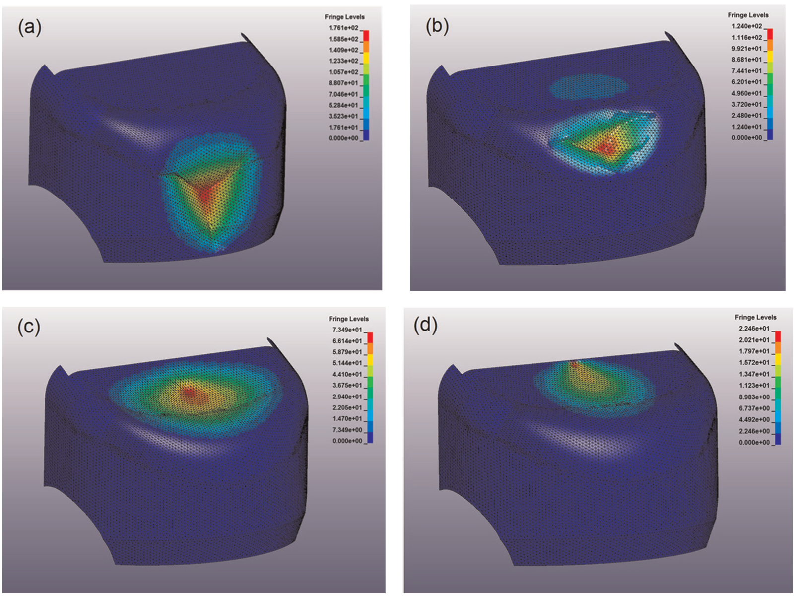
Ls-Dyna displacement results for material configuration no. 4. Impact cases 1(a), 2(b), 3(c) and 4(d) at their moments of maximum displacement.

Ratio between the final internal energy and the initial energy obtained for all impact simulations carried out.
Finally, in order to assess all the variables involved in the optimization of the frontal component and to be able to compare its performance at different impact conditions, it was considered the impact index defined in equation (1). The coefficient 107 was used in this equation to avoid decimals and gain clarity in data processing

This parameter was calculated for each material configuration and impact case analysed, and then an improvement ratio with respect to the initial prototype was obtained by means of equation (2)
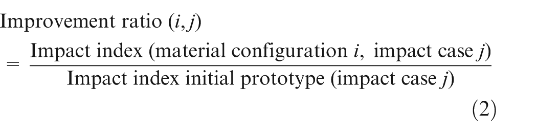
Figure 22 shows the improvement ratios obtained for all material configurations apart from nos 3 and 7, which presented material failure with excessive damage. Impact cases for WAD 1700 position were not taken into account because of the excessively high and not corresponding to reality HIC15 values obtained when the impactor contacted with nodes constrained at the upper edge of the component. In this sense, WAD 1500 position represented more accurately the impact at 295.7 J on the upper area of the component.

Improvement ratios for material configurations nos 2, 4, 5, 6, 8 and 9.
The test conditions considered in the initial prototype were also simulated, corresponding to an impact energy of 444.68 J. Taking into account the improvement ratios obtained, material configuration no. 4 reached the maximum score in all cases except for the WAD 1500 impact case with the ratio of 1.51, which however gave quite similar values for all configurations, ranging 1.05/1.70. Table 6 collects all the results obtained from the impact simulations that were considered in the optimization process.
Results’ table obtained from the impact simulations.

WAD: wrap around distance; PVC: polyvinyl chloride.
Not valid: constrained nodes’ influence.
Not valid: material failure.
On the whole, within the analysed alternatives, material configuration no. 4 was considered the best option for the optimization of the initial prototype. This material configuration is a composite sandwich comprising the following:
Sandwich inner layer: 0.8-mm-thick glass fibre mat–fabric with density of 300 g/m2 and matrix in polyester resin;
Core: 10-mm-thick PVC foam with density of 60 kg/m3;
Sandwich outer layer: 1.75-mm-thick glass fibre mat–fabric with density of 650 g/m2 and matrix in polyester resin;
Exterior coating: 0.5–mm-thick polyester gelcoat.
Conclusion
Nowadays, the standard layout of internal combustion engine, electric and hybrid vehicles that can be found in the market locates a great amount of components comprising the centralized drivetrain, under the hood of the vehicle. The implementation of in-wheel motor architectures32,33 makes possible to gain space at the front of the vehicle, eliminating all bulky rigid parts that pedestrians are liable to suffer damage with, in case of an impact. At the same time, this means that a greater distance will be available for increasing the energy absorption level in the case of VRU impact; therefore, current test methods concerning pedestrian protection should be adapted to these new capabilities. When in-wheel motors are implemented, new ideas for pedestrian protection can be developed taking into account the generation of free space at the front of the vehicle. The frontal component proposed in this article has been designed considering the application of in-wheel motor technologies to L7e vehicles. The process was based on experimental tests and numerical simulations, taking into account different impact conditions to achieve an optimum performance of the component in terms of VRU’s protection, repairability and dimensional constraints.
Once the numerical model was experimentally correlated, eight different material configurations were proposed and simulated, in order to improve the performance of the frontal component. The complexity of an optimization process considering at the same time a maximum safety and a minimum damage in the component made necessary to define an impact index which accounted for the positive or negative contributions of each of the following parameters: mass, HIC15, maximum displacement and energy absorption ratio. It was found that the use of this index was very useful to compare the behaviour of different material configurations and different impact conditions by means of an improvement ratio with respect to the initial design.
It must be taken into account that displacements in the range of 176 mm were reached with the selected material configuration; therefore, it will be fundamental to release enough free space from the front of the vehicle in order to achieve an appropriate safety in frontal pedestrian impacts. This result also points out that high safety levels in pedestrian frontal impacts with L7e category vehicles are possible, by incorporating composite sandwich frontal structures with an adequate energy absorption capacity.
Footnotes
Acknowledgements
Partners in the OPTIBODY consortium are as follows: University of Zaragoza (Spain), Politecnico di Torino (Italy), PIMOT (Poland), IDIADA (Spain), CENTRO ZARAGOZA (Spain), MONDRAGON Automoción (Spain), AMZ-KUTNO (Poland), ITALDESIGN-GIUGIARO (Italy), BELLA (Poland) and SSAB Tunnplat AB (Sweden).
Academic Editor: Yucheng Liu
Declaration of conflicting interests
The author(s) declared no potential conflicts of interest with respect to the research, authorship, and/or publication of this article.
Funding
The author(s) disclosed receipt of the following financial support for the research, authorship, and/or publication of this article: This study was financially supported by the project OPTIBODY (Project no. 266222) 34 and co-financed by European Commission (7th RTD Framework Programme).