
Abstract
Based on the elasto-hydrodynamic lubrication theory, a 2-degree-of-freedom nonlinear dynamic model of helical gears with double-sided film is proposed, in which the minimum film thickness behaves as a function of load parameters, lubricant parameters, and the geometry of the contact. Then, the comparison of the hysteresis loops in different gear models shows the soundness of the presented model. Using numerical method, the time evolution of lubricant normal force, minimum film thickness, and lubricant stiffness is obtained in order to demonstrate the influence of the driving torque and pinion’s velocity. The results obtained in this article can contribute to the root cause for the gear vibration and show that the hydrodynamic flank friction has almost no influence on the gear system.
Introduction
The vibration and noise are well-known issues in gear pairs because the demand for acoustic comfort is constantly increasing, and the lubricant in the opportune backlash is the fundamental factor affecting a gear’s dynamic performance. Actually, in addition to reducing power consumption, heating, and wear, the lubricant film between gear backlashes actually provides the main dissipation resource through which vibration and noise can be reduced.
Lubricated contact analysis has been previously conducted for lightly loaded cases under rattle conditions, where the regime of lubricant is considered to be hydrodynamic.1–5 Since there is always a formed film of lubricant between the teeth flanks under low-load condition, there is no direct “impact” with metal-to-metal. However, there are strong or smooth fluctuations of the film thickness instead, which can change the force transmitted between the teeth flanks.
The studies for lubricant system are always based on the hydrodynamic theory. Amarnath et al. 6 considered the estimation of operating conditions such as film thickness and their effects on the fault growth on teeth surface to assess wear in spur gears of back-to-back gearbox. Barbieri et al. 7 presented a new method for modeling the fluid film lubrication in gears by considering both the elasto-hydrodynamic lubrication (EHL) and the dynamic load between the mating tooth pair.8,9 Guilbault et al. 10 introduced a lubricated impact analysis between the teeth and illustrated the effects of the lubricant on the inverse relationship between the global mesh damping and the applied load. Huang et al. 11 constructed a time-varying gear mode by incorporating the lubrication effect derived using EHL and squeezed film theories. Tangasawi and colleagues12–14 developed a tribo-dynamic model to show that squeeze film motion plays a significant role in the propensity of transmission system to rattle. Based on Theodossiades’ model, Liu et al. 15 characterized the damping and stiffness in lightly loaded lubricant gear system employing a trace method. Then, Liu 16 investigated the influence of the lubricant films located in the backlash between meshing gear teeth pair on the gear dynamical behaviors, and the numerical simulation showed that the influence of the lubricant film on the coast side is significant under low loading, but under higher drag torques the influence is diminished.
The literature survey indicates that the nonlinear dynamic modeling of gear problems is well described and generally well understood. However, a thorough understanding of the lubricant film characteristics is still needed to ensure a rapid and precise representation of the gear mesh model. To the authors’ knowledge, constructing a double-sided lubricant film model that considers the minimum film thickness (MFT) is novel. Assuming relatively soft contacts, Hooke 17 presented the equations for the MFT. Nevertheless, in most of the literature, the MFT in the gear system was neglected12–14 or considered as a roughness-dependent constant.8,9,18,19 On the other hand, it is impossible for the engine to work regularly and generate a constant driving/driven torque for the gearbox. 20 The numerical analysis of driven torque has been studied on spur gears,21–25 helical gears 7 and gear pairs. 26 However, to the authors’ knowledge, the driving torque on the idler gear is still poorly understood and an analytical formulation of the problem could be useful in order to evaluate its influence.
The objective of this work is to extend the methodology in reference papers15,16 and focus on the above-mentioned issues. The rest of this article is organized as follows: in the next section, an elasto-hydrodynamic model of helical gear is presented by considering the MFT, in which the lubricant in both driving and coast side is considered. Then, the lubricant normal force, MFT, and lubricant stiffness are investigated with different rotational speeds of the pinion and driving torque using the numerical method. Subsequently, the influence of the hydrodynamic flank friction is illustrated in both time and frequency domains. In the last section, concluding remarks are presented.
Dynamics system model
Governing equation
The system in this article consisting of two gears can be modeled as 2-degree-of-freedom (DOF) lumped system with rotational displacements (


where

here, t is the time in second;
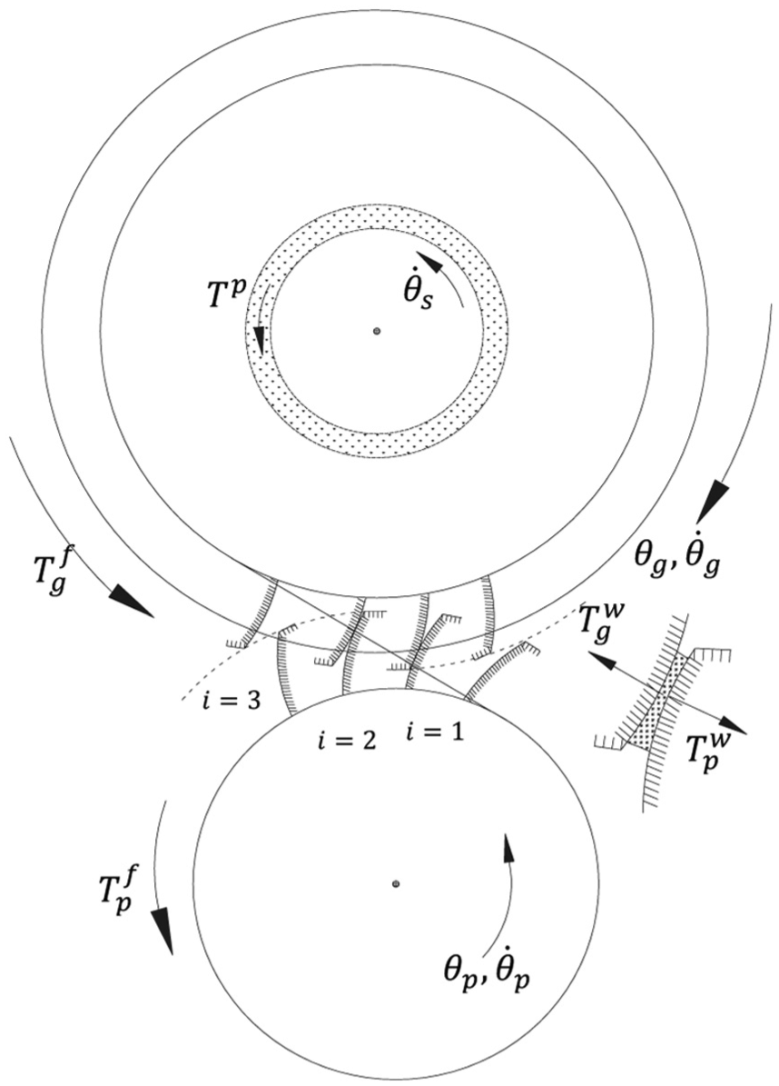
Sub-system of gear system.
The torques generated by the lubricant reaction


where
The lubricant forces
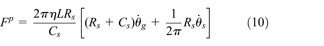
With lightly loaded contacts, the regime of lubrication is iso-viscous rigid. Through analytical solution of the Reynolds’ equation, the lubricant reaction force

where L is the gear face width,

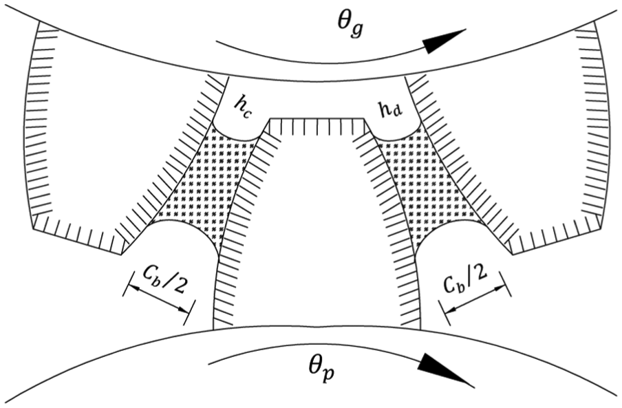
Gear backlash with lubricant.
Due to the viscous shear of the hydrodynamic film between the meshing teeth, the flank friction obtained by half-Sommerfeld conditions is acting in parallel to the flank end faces, defined as follows

here,
The friction introduced by the full-complement needle roller bearings, upon which the gear wheel is mounted onto its retaining shaft (Petrov friction), can be calculated as
here,
The arms of forces
The time-variation in the parameter is one of the most important parameters in the analysis of this article. The moment arms of the friction forces continue to change as meshing progresses 28

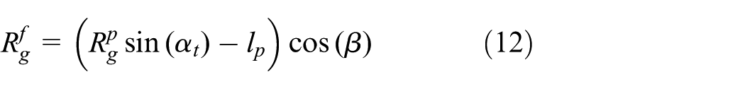
here,

The instantaneous contact radius of the pinion and wheel can be obtained as

where

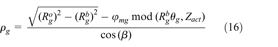
here, a is the center distance between the pinion and the gear;

Lubricant film thickness
Since the surface of the meshed teeth is not smooth completely for processing and wear and tear, it is impossible for the gear teeth to be completely “metal-to-metal” contacted due to the lubricant. Thus, a tiny relative separation will occur for the contact teeth. For this reason, an additional surface separation should be considered for both the dynamic transmission error and the lubricant film thickness. Based on Dowson–Higginson equation, Akin 29 developed the elasto-hydrodynamic equations and obtained the MFT needed for use in various types of gears. Based on this, rather than using a roughness-dependent invariable MFT,8,9,18,19 the elasto-hydrodynamic equation for MFT in this article is described as below

here,
Therefore, the lubricant dynamic transmission error can be described as follows
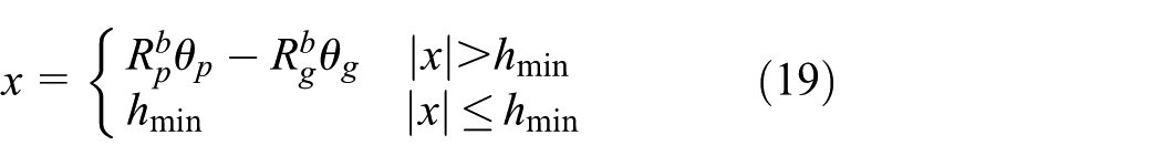
The instantaneous value of lubricant film thickness with the distance between the approaching teeth in the normal section is obtained as follows

here

Results and discussion
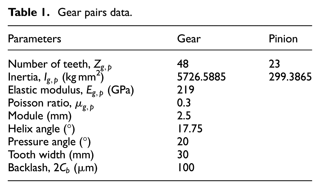
The basic parameters for the helix gear system used in this study are shown in Table 1. The lubricant is a synthetic gear oil 75W-90BO with indicating value of dynamic viscosity
Gear pairs data.
In order to guarantee computational precision, the system is calculated employing variable step Runge–Kutta numerical integration routine (ODE23s) that is suitable for a “stiff” ordinary differential equation, because the ODE23s solver renews the Jacobian matrix for every time step.
30
On the other side, extremely small integration step is required because the interval of the changes in the lubricant film thickness is negligibly small, and the maximum step

here,
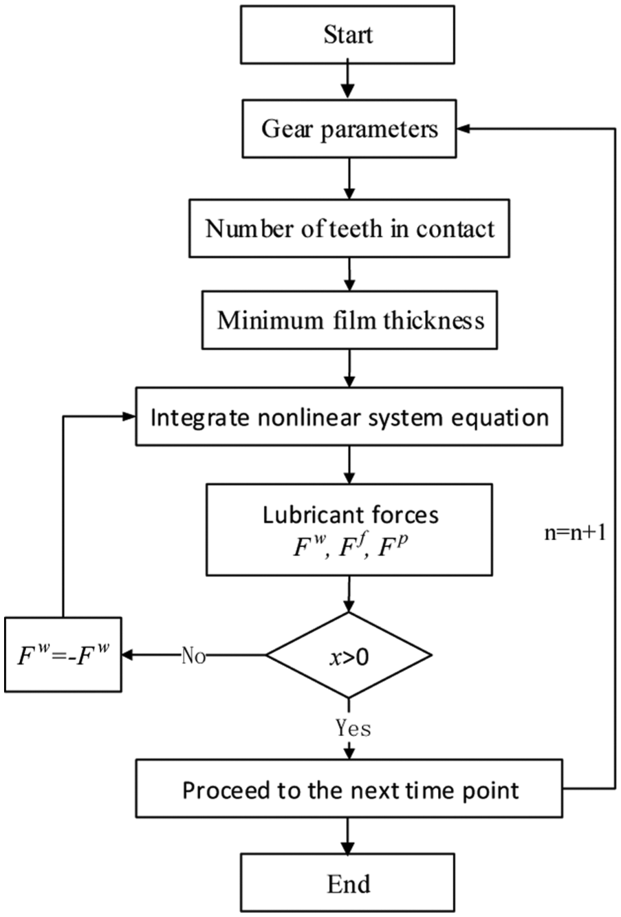
Computational flowchart.
The effect of the MFT on the hysteresis loop for the different model is shown in Figure 4, in which the energy from the work along the top of the loop is removed and that along the bottom is returned, resulting in the area of the loop being the energy loss. As one can see from these figures, the geometrical aspect of these hysteresis loops is totally different when the dynamical transmission error value tends to 0. Here, the shape of the hysteresis loop considering the MFT in the double-sided film model is more similar to that in the reference papers.31,32

Hysteresis loop for single-side lubricant (a) without considering MFT and (b) considering MFT and double-sided lubricant (c) without considering MFT and (d) considering MFT.
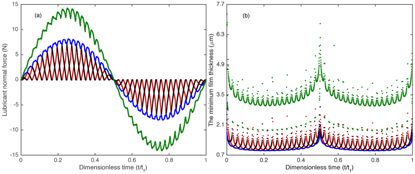
Based on the proposed model, Figures 5 and 6 demonstrate the time histories for the lubricant normal force and the MFT under constant/fluctuated driving torque, respectively. The horizontal axis represents the dimensionless time normalized by the time of one mesh circle

Time histories under constant driving torque for (a) lubricant normal force and (b) MFT.
Time histories under fluctuated driving torque for (a) lubricant normal force and (b) MFT.
As is well known, the pinion’s velocity and the driving torque are the key parameters in gear dynamics, which determinates the vibration characteristics of the gear system. It is easy to be found in Figure 7 that at the moment that the lubricant normal force and the lubricant stiffness reach the highest point, the MFT has the smallest value simultaneously. And the MFT is reduced when the lower pinion’s velocity is applied as shown in Figure 7(b). Observe that the change in the MFT and the lubricant stiffness are mainly dependent on the pinion’s velocity, but the lubricant normal force is insensitive to the different pinion’s velocity mainly because the amplitude of the external excitation torque is unchanged. To explore the effect of driving torque on the time evolution of the lubricant normal force, the MFT, and the lubricant stiffness, three levels of driving torque are illustrated in Figure 8. It can be seen that an increase in driving load will lead to a higher lubricant stiffness that will reduce the MFT. The conclusions shown in Figures 7 and 8 clearly reinforce the reasons that the gear rattles mostly happen with lower velocity and driving torque.

Time histories for (a) lubricant normal force, (b) MFT, and (c) lubricant stiffness.
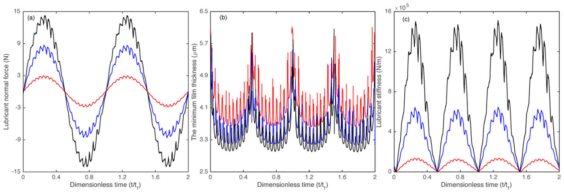
Time histories for (a) lubricant normal force, (b) MFT, and (c) lubricant stiffness.
From another case study, the evaluation of the hydrodynamic flank friction is of interest. The resulting response curve in two excitation periods is shown in Figure 9(a). And the simulation results with/without considering the effect of the hydrodynamic flank friction are plotted both in the time and frequency domains. In these results, note that the hydrodynamic flank friction has very little effect on the MFT and its spectrum, and the entire response curve both in time and frequency domains coincides quite well with each other. This is mainly because the hydrodynamic flank friction is much smaller than the lubricant normal force as shown in Figures 7(a) and 8(a). Thus, the hydrodynamic flank friction does not appear to affect dynamic gear system, and the effect of the hydrodynamic flank friction can be neglected.

Time history curves of (a) hydrodynamic flank friction, (b) MFT, and (c) FFT spectrum of the MFT.
Conclusion
This article proposes a double-sided film model for involute gear system based on the EHL theory, in which the MFT behaves as a function of load parameters, lubricant parameters, and the geometry of the contact. This article sheds some light on the complexity of issues and does provide a good understanding of the mechanisms underlying the contributions of various input parameters (driving torque and pinion’s velocity) in attenuation or inducement of the MFT. The following conclusions can be drawn from the results obtained in this article:
Given the different shapes of the hysteresis loop in Figure 4, the double-sided film model considering the influence of the MFT shows more soundness than that neglecting the MFT.
The curves of the lubricant normal force are linear approximation under constant driving torque, which are totally different from that with fluctuated driving torque. The fluctuated driving torque increases the lubricant normal force, and then reduces the MFT, which could enhance the vibration by strengthening the fluctuations of the film thickness.
The vibration mostly happens with lower driving torque and lower pinion’s velocity, and the influences of the driving torque and pinion’s velocity are totally different: the pinion’s velocity have no contribution to the lubricant normal force, and the change in the MFT only depends on the lubricant stiffness. However, in the case of different driving torques, the MFT not only depends on the lubricant stiffness but also depends on the lubricant normal force.
The hydrodynamic flank friction is much smaller than the lubricant normal force so that there is almost no effect on gear system. Therefore, in order to reduce the complexity of the multi-DOF gear system considering the mass eccentric induced by tooth breakage defect, the hydrodynamic flank friction can be neglected. This forms the next step in the ongoing investigations.
Footnotes
Academic Editor: Xiaobei Jiang
Declaration of conflicting interests
The author(s) declared no potential conflicts of interest with respect to the research, authorship, and/or publication of this article.
Funding
The author(s) disclosed receipt of the following financial support for the research, authorship, and/or publication of this article: The authors acknowledge the financial support from National Natural Science Foundation of China (grant nos 51305378 and 51605412), Jiangsu Provincial Key Laboratory of Automotive Engineering (QC201306), China Postdoctoral Science Foundation–funded project (2016M590643), Jiangsu Provincial Science and Technology Department (BY2015057-25), and the Research Laboratory of Mechanical Vibration (MVRLAB).