
Abstract
A damaged member in a truss structure leads to a variation in the initial responses of its adjacent members. A flexibility-based approach extracting from the modal data should be implemented as one of the structural damage detection methods. The frequency response function data as dynamic measurements provide more information on the system characteristics compared with modal data. Proper orthogonal modes from the frequency response functions extracted in the given frequency ranges and their modified forms can be utilized as damage indices to detect damages. This study considers damage detection of a truss structure using a frequency response function–based approach transformed to the proper orthogonal modes and a flexibility-based approach using the first few modal data for undamaged and damaged states. The utilization of these two methods is compared through numerical experiments on truss structures. The methods can rarely detect the damaged member accurately, but a group of damage-expected members is detected despite the existence of external noise. It is shown that the frequency response function–based approach can be utilized more explicitly than the flexibility-based approach.
Introduction
Structural health states should be monitored regularly to evaluate the structural performance. The repair and maintenance of performance-deteriorated systems are essential for improving the durability and recovering the performance. The technology for evaluating the structural performance has been gradually enhanced with the advent of the newest measurement sensors. Measurement data in the time domain or frequency domain can be utilized to evaluate the health state of the structure.
There has been significant research dedicated to evaluate the structural performance and to detect a deteriorated member or location. Doebling et al. 1 presented a review of various vibration-based damage identification methods. The majority of the damage detection methods for truss structures have considered the damage in axial members and focused on their strain change. Ji et al. 2 observed that the damage location and degree of the truss member can be effectively diagnosed by the axial strain change using the finite element analysis. Weber and Paultre 3 identified damage in the truss using a finite element model updated with modal parameters obtained from ambient vibration measurements. Zheng et al. 4 provided a Bayesian inference framework to infer damage in truss bridges. Zheng and Yu 5 presented a sampling method of the traditional Markov chain Monte Carlo incorporated with the structure finite element model for implementing damage identification of truss structures. Kim et al. 6 presented a damage identification technique for truss structures based on the force method and the micro-genetic algorithm. Liu et al. 7 presented a damage detection method using the square difference in the elemental modal strain. Lim and Kashangaki 8 provided a damage detection method by comparing the Euclidean distances between the measured mode shapes and the best achievable eigenvectors that are the projection of the measured mode shapes onto the subspace. Yang and Jin 9 considered a damage detection method to identify damages of truss structures by changes in the first few natural frequencies between undamaged and damaged states. Jin et al. 10 presented a two-stage structural damage identification method using the generalized energy change of each structural element and the first-order sensitivity of the structural eigenvector. Wang et al. 11 presented a two-step damage detection method using the fourth strain statistical moment and the least square optimization algorithm. Siriwardane 12 proposed a technique to locate the damaged region of railway truss bridges based on variations in the modal parameters versus the position of the damage.
The change in the flexibility matrix at the undamaged and damaged states has been utilized as an index to detect damage. Yang and Sun 13 localized and quantified the damage in structures based on the Euclidean distance between the measured flexibility change and the best achievable flexibility changes. Montazer and Seyedpoor 14 presented a damage detection method considering the strain changes in structural elements using the columnar coefficients of the flexibility matrix estimated via the modal analysis between undamaged and damaged states.
One of the measurement data types is the frequency response function (FRF) data set. The FRF data provide more information because the modal data are extracted from a very limited frequency range around the resonance. The FRF data can be utilized to identify the dynamic parameter properties such as the mass, stiffness, and damping matrices. Proper orthogonal decomposition (POD) analysis captures most of the kinetic energy in the least number of modes possible. Yu et al. 15 considered vibration-based damage detection using the FRF data normalization, principal component analysis, kernel principal component analysis, and the fuzzy c-means clustering algorithm. Wang et al. 16 developed a damage identification approach to identify the location and the extent of the damage using proper orthogonal modes (POMs) of the acceleration dynamic response and particle swarm optimization. Bandara et al. 17 presented a neural network–based damage detection method using the FRF data, artificial neural networks, and recognized damage patterns.
This work considers the truss structure damage detection method of identifying damage from (1) the POM extracted from the difference in the FRFs at undamaged and damaged states and (2) the variation in the flexibility matrices at both states. It is difficult to detect the specific damaged member in the structure because of the structural continuity. This work traces the damage-expected members using FRF-based and flexibility-based methods. Dividing the entire structure into structural member groups such as upper and lower chords, diagonal members, and vertical members, the effectiveness of both approaches can be compared for each member group. The FRF-based method can rarely detect the specific damaged member but can determine the damage-expected members. The utilization of the proposed method is illustrated in truss structure applications.
Formulation
A truss is composed of axial members joined at their end points. The damage detection of a truss structure traces the deteriorated member in the entire structure using a few response data sets measured at all the degrees of freedom (DOFs) of the finite element truss model. Assuming that the truss is composed of members with identical material properties, the physical parameter matrices of elements in the intact state can be estimated and established as the baseline data. By comparing the response variations of members at intact and measurement states, a damaged member can be traced. The variation in the dynamic response of the truss structure due to the damage of an axial member is not significant enough to allow the damage to be easily detected. The measurement results include external noise such as measurement and environmental errors and can lead to inaccurate subsequent analyses and cause difficulty in detecting damage.
Damaged component members exhibit response changes after the occurrence of damage at lower and upper chords or to diagonal and vertical members. The upper and lower chords of a truss structure subjected to a flexure exhibit more response variation and can be detected more explicitly than the vertical and diagonal members because of greater variation in the responses. In the following, the FRF-based approach and the flexibility-based approach are introduced.
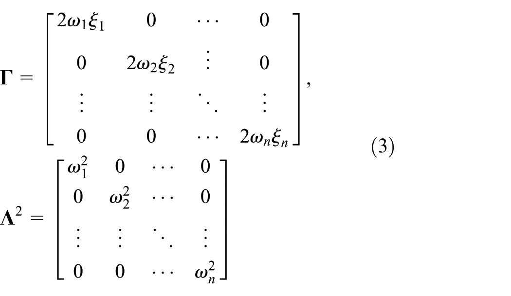
The dynamic behavior of a structure that is assumed to be linear and approximately discretized for n DOFs can be described by the following equation of motion

where
Substituting

where
Inserting

where
A modal transformation using the actual eigenvalues and eigenvectors leads to the representation of the FRF matrix for an excitation frequency

with
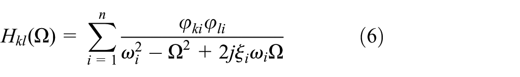
describing the single output
The FRF change matrix before and after the occurrence of damage of the rth element of the structure,

where
For the rth member, let

where
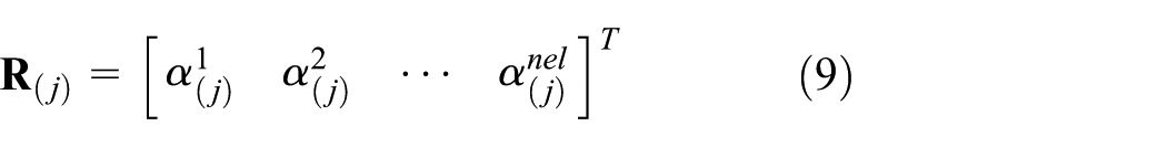
The measurement data are expressed by a finite number of points in space and frequency. Suppose that s linear snapshots of the response

where the subscript (j) represents the FRF data at the jth frequency
The POD of this discrete field involves solving the eigenvalue problem. Let

Solving the eigenvalue problem of equation (11) at the core of the POD method, equation (11) satisfies

where the eigenvalues are arranged as follows

where the eigenvalues
The POMs may be used as a basis for the decomposition of

The POMs are arranged as follows

This work detects the damage from the POM corresponding to the first POV. The FRF-based approach to predict the damage is processed according to the flowchart in Figure 1.

Detection process of damage-expected member group.
The flexibility matrix is also utilized to evaluate the structural performance and can be estimated from modal analysis data. Neglecting the excitation frequency and the damping effect in equation (5), the flexibility matrix
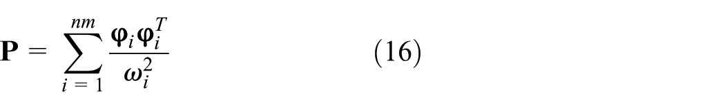
where
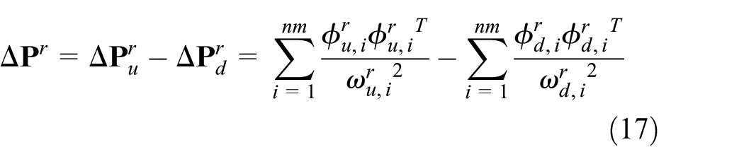
where the subscripts u and d indicate the undamaged and damaged states, respectively. For the rth member, let

where
Numerical example
The damage detection of a plane truss structure model with a single damaged element was considered. The truss is composed of 14 nodes and 30 members with all nodal points and members numbered in Figure 2. All members have the same elastic modulus of 200 GPa, cross-sectional area of 2.5 × 10⁻³ m2, and density of 7860 kg/m3. The truss has a single span with a length of 28 m, height of 3 m, and bays that are 4 m long. It is simply supported with its two translational DOFs restrained at all nodes. Three different damage cases were considered, with the damage at an upper chord member ⑧, a lower chord member ⑨, and a diagonal member  . The damage was taken as a 20% loss in stiffness. The numerical example compares the FRF-based and flexibility-based approaches for damage detection.

A plane truss structure (unit: mm).
The mode shapes for undamaged and damaged states were calculated using the finite element model. The flexibility matrices using the first three normalized mode shapes were estimated depending on the existence of external noise. Each finite element has four DOFs, and the summation of the diagonal elements in the difference of the 4 × 4 flexibility matrices at both states is determined using equation (18). The flexibility-based method traces the damage-expected members using the difference in the flexibility by member groups at both states. Similarly, the FRF matrices at both states and their difference are estimated. The summation of diagonal elements of the 4 × 4 absolute FRF matrix of each member in equation (7) at each excitation frequency is estimated using equation (8). The summation matrix within a specific frequency range including the first resonance frequency is extracted to calculate the POMs. The values with and without external noise are considered, the POMs corresponding to the first POV are compared, and the damage-expected members are traced by member groups.
The natural frequencies of the truss structure before and after the appearance of the damage at element ⑧ are listed in Table 1. It is shown that the natural frequencies of the damaged structure decreased due to the stiffness loss. The FRF matrices were numerically calculated according to the excitation frequency at the undamaged and damaged states. Figure 3(a) represents the receptance magnitude values in the horizontal direction at node 5 due to the impulse in the same direction. In the plot, the resonance frequencies occur at very similar values as the natural frequencies in Table 1. Figure 3(b) compares the difference in the first three normalized mode shapes before and after the occurrence of the damage of a 20% stiffness loss at element ⑧. It is shown that the damage affects the mode shapes as well as the FRFs, which can be then be utilized as damage indices to evaluate the damage.
Natural frequencies unit: Hz.

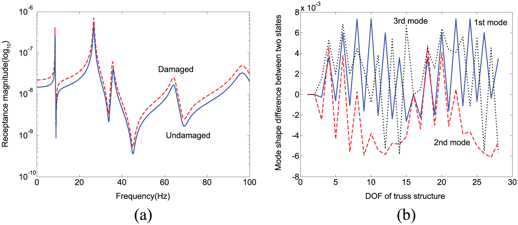
FRF and mode shape curves: (a) receptance magnitude curves of undamaged and damaged structures and (b) difference curves in the mode shapes of the first three modes of undamaged and damaged structures.
The difference in the POMs extracted from the noise-free receptance magnitude at undamaged and damaged states is displayed in Figure 4. The flexibility matrices at both states were determined using the first three modal data, and the differences obtained from equation (18) are also plotted in Figure 4. Figure 4 compares the responses by member groups such as upper chord members, lower chord members, diagonal members, and vertical members, as shown in Table 2. Extracting the FRF differences in the range of 8.5–8.7 Hz including the first resonance frequency with the 0.02 Hz step, the POM corresponding to the first POV was estimated for the member groups. The damaged element is located at the region that represents the abrupt change in the plot. It is observed that both the FRF-based and the flexibility-based approaches display the abrupt change at the same elements. However, the POM curve using the FRF data provides more explicit information on the damage-expected elements than the difference using the flexibility-based method because the former used estimations from the full modes and considers more modal data sets than the latter. Despite this observation, both methods have the limitation of being unable to indicate the specific damaged member.

Differences in noise-free FRF magnitude and noise-free flexibility at undamaged and damaged states: (a) upper chord members, (b) lower chord members, (c) diagonal members A, (d) diagonal members B, and (e) vertical members.
Members categorized by member group.

Measurement data may be contaminated by external noise so that they do not coincide with the analytical results. This inconsistency can lead to inaccurate results in the subsequent design and analysis. The validity of the FRF-based and flexibility-based approaches should be evaluated by investigating the effects of the external noise in the measurement data.
The external noise for this numerical simulation was taken as the following values on the FRF-based and the flexibility-based approaches, respectively
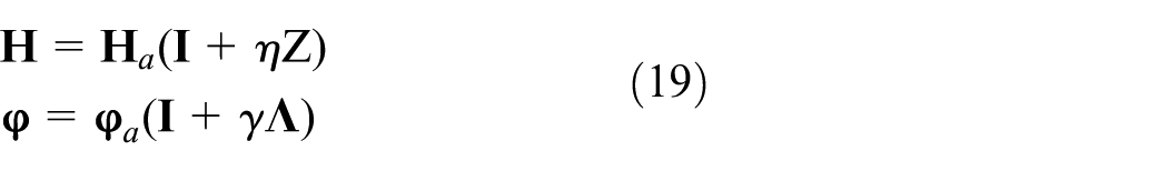
where
Figure 5 represents the POM curves using FRF difference at intact and damaged states by member group of truss structure containing 2% external noise in equation (19) with the damage at upper chord member ⑧, lower chord member ⑨, and diagonal member . The external noise in this numerical experiment was generated by the mean values of 100 repeated random values. This represents an obstacle to be overcome for damage detection. Figure 5(f) exhibits the variation rate (%) in FRF matrix between undamaged and damaged states at the frequency of 8.7 Hz. The POM curves exhibit different shapes depending on the damage location. The damage-expected member locates at the region to represent the abrupt change in the plot. The POM curves extracted from FRF differences provide explicit information on the damaged members. Figure 7(a) displays the damage-expected members represented in Figure 5 by member group of the truss structure with the damage at upper chord member ⑧ and is expressed by the consecutive slashes. The actual damaged member ⑧ is included in the damage-expected members, but the damage is not located at member ⑧ only. It indicates that the damage results in axial stiffness deterioration of the corresponding member. Its deterioration affects the adjacent members of the damaged members because of the structural continuity and causes the abrupt change of the POM curve. Thus, it is difficult to accurately indicate the damaged member. Similarly, Figure 7(b) and (c) represents the damage-expected members of the truss structure indicated in Figure 5 with the damage at lower chord member ⑨ and diagonal member , respectively. The plots provide a similar observation as the previous damage case.
Differences in FRF magnitude at undamaged and damaged states: (a) upper chord members, (b) lower chord members, (c) diagonal members A, (d) diagonal members B, (e) vertical members, and (f) FRF variation due to noise at the frequency of 8.7 Hz. The solid, dashed, and dotted lines indicate the structures with the damage at the members ⑧, ⑨, and , respectively.
Figure 6 exhibits the flexibility difference curves estimated from the first three modal data containing 2% external noise in equation (19). The variation rate of flexibility matrix at undamaged and damaged states due to the damage at member ⑧ is exhibited in Figure 6(f). The change in the mode shapes leads to the change in the flexibility matrix. The addition of the external noise affects the modal data at damaged state. The flexibility matrix at intact state is analytically determined by the finite element model. Results similar to the FRF-based approach in Figure 5 were observed. As a result of the numerical simulation, the damage-expected members can be estimated, as shown in Figure 8. The FRF-based and flexibility-based damage detection methods that apply to truss structures can be utilized to detect the damage-expected members despite the existence of external noise. However, the FRF-based approach can be utilized to detect more explicit damage members than the flexibility-based approach. Both methods provide information on the damage-expected members but can rarely detect the only damaged member because the truss structure members respond interdependently to the external excitation.
Flexibility difference at undamaged and damaged states: (a) upper chord members, (b) lower chord members, (c) diagonal members A, (d) diagonal members B, (e) vertical members, and (f) variations of full mode shapes due to noise. The solid, dashed, and dotted lines indicate the structures with the damage at the members ⑧, ⑨, and , respectively.
Damage-expected members obtained from FRF-based method: (a) damage at member ⑧, (b) damage at member ⑨, and (c) damage at member .
Damage-expected members obtained from flexibility-based method: (a) damage at member ⑧, (b) damage at member ⑨, and (c) damage at member .
Conclusion
Stiffness deterioration in one of the members of a truss structure that affects the responses of the adjacent members. Because of the continuity through the member joints, each member responds interdependently. Thus, it is difficult to accurately indicate the damaged member. This work considered the detection of damage-expected members of truss structures using the FRF-based and flexibility-based approaches. The FRF-based approach utilizes the POMs from the FRF data in the given frequency ranges. Both methods can be applied to the detection of the damage-expected members despite the existence of external noise. The FRF-based approach can be utilized more explicitly than the flexibility-based approach because the FRFs include more modal information than the flexibility-based approach. The validity of both methods was illustrated by numerical simulations on damaged truss structures.
Footnotes
Academic Editor: Yonghui An
Declaration of conflicting interests
The author(s) declared no potential conflicts of interest with respect to the research, authorship, and/or publication of this article.
Funding
The author(s) disclosed receipt of the following financial support for the research, authorship, and/or publication of this article: This research was supported by Basic Science Research Program through the National Research Foundation of Korea (NRF) funded by the Ministry of Education (2013R1A1A2057431).