
Abstract
Fluidized bed dryers are widely used in the food and chemical industries to dry wet granular solids fast and effectively. The mathematical models of fluidized bed drying require a transfer coefficient between the gas and the particles and drying parameters to investigate the influence of the operating parameters of the devices. A pilot plant fluidized bed dryer is developed to study the heat and mass transfer phenomena during the drying process. A volumetric heat transfer coefficient is applied for modeling fluidized bed dryers. A modified Nusselt number is defined to compare our measurement results and those of the literature.
Keywords
Introduction
Heat transfer is widely used to remove moisture from wet solids by evaporating the liquid into the vapor state. In most drying operations in agriculture, in the pharmaceutical and food industries, the evaporated liquid is water and the purge gas usually used is air.
During convectional drying, simultaneous heat and mass transfer occurs between the wet material and the drying gas. Heat flux is induced by the gas drying the material and, at the same time, the moisture of the material diffuses into the drying gas. Fluidized bed dryers are used for drying wet granules, powders, and other bulk solids in a fast and effectively way. Further important advantages of the equipment can be identified as good mixing of solids, as well as relatively high rates of heat and mass transfer, compared to other technologies. 1 To improve operation efficiency, monitoring and controlling techniques of fluidized bed dryers have been developed rapidly in the past few years. Therefore, it is an imperative to review recent trends in the application of different experimental techniques. 2 It is important to be clear about heat and mass transfer processes during drying and to apply sufficiently accurate thermal models to describe the processes concerned in order to determine device parameters. 3 There are some mathematical models applied in the literature describing fluidized bed drying. 4 Widely used approaches for modeling fluidized bed dryers are as follows:
1: Mathematical models with heat and mass balance equations involving transfer coefficients;
2: Empirical correlations involving the parameters of drying;
3: Models which assumed the bed to be made of several phases (emulsion, cloud, and bubble phases) with heat and mass transfer between them. 5
The first approach involves the solution of differential equation systems. The mathematical models are based on mass and energy balance equations. 6 The models are suitable for describing the temperature and moisture content distributions in the material and in the gas along the length of the dryer, and in the function of drying time. 7 The model can be solved numerically since material characteristics and transfer coefficients are given. Heat and mass transfer coefficients can be determined from criterial equations Nu = f(Re, Pr), Sh = f(Re, Sc).
The second approach sets up empirical forms for describing variations in the moisture content of the material in the function of drying time. This method requires a wide range of experimental data. 8 The model is based on the solution of Fick’s second law of diffusion for spherical solids. 9
The third approach relates to describing the flow and hydrodynamic characteristics of the bed, including the bubble, cloud, and emulsion phases. This model describes flow, temperature, and moisture profiles, as well as heat and mass transfer characteristics between the phases. 10 The model also contains the heat and mass transfer characteristics between the phases of bubble and cloud, cloud and interstitial gas, and bubble and interstitial gas, respectively. 11
Mathematical models with heat and mass balance equations involve the solution of differential equation systems. Furthermore, using these models, the main parameters of the equipment can be specified without measurements. The input parameters of the mathematical models are heat transfer coefficients in addition to geometry and drying characteristics. The heat transfer coefficient can be calculated from criterial equations, which can be determined by measurements. 12 The measured values can be verified using numerical simulation 13 and can be validated by experiments. 14 The modeling of fluidized bed dryers requires knowledge of the heat transfer coefficient between gas and solid particles. It is rather difficult to measure the heat and mass transfer surface of the fluidized material. Determining the contact surface of particles involves a number of uncertainties because of the irregular surface of particles, the standard deviation of their size, and the non-ideal contact between the gas and the material.
In the literature, there are several Nu = f(Re) equations to determine the heat transfer coefficient between solids and the drying gas.
Kettenring et al. 15 were one of the first who published transfer coefficients between gas and solids for drying silica gel and aluminum oxide particles of narrow size range, heated and fluidized by air.
Ciesielczyk et al. 16 used polytetrafluoro-ethylene, ammonium sulfate, sand, and silica gel in their experiments. In all, 208 measurements were performed, 97 out of which are suitable to study the falling drying rate period as well. Particle sizes ranged from 0.339 to 1.24 mm, the inlet temperatures were 333 and 363 K, static bed height varied between 150 and 240 mm, and air velocity ranged from 0.2 to 1.8 m/s. The initial moisture content of the materials was constant in each measurement.
Alverez and Shene 17 used three different types of materials for their pilot plant fluidized bed drying experiments: soya meal, sawdust, and fish meal. Drying gas velocity ranged between 2.8 and 3 m/s, and the inlet temperature was 65 to 105°C.
Kumaresan and Viruthagiri
18
carried out experiments in the constant drying rate period on a fluidized bed dryer in batch operation. The diameter of the experimental apparatus was 55 mm, and the height was 435 mm. Ammonium chloride particles were used for the experiments with particle diameters between 0.495 and 0.912 mm, inlet air velocity was 1.136–1.391 m/s, inlet air temperature ranged between 60°C and 75°C, the initial moisture content was 0.04–0.06
Mohammed 19 performed his experiments on a spouted bed system, which is similar to fluidized bed dryers. The main purpose of his work was to determine heat transfer characteristics in an industrial-scale prototype spouted bed system. He used soybean of three mean sizes: with 6, 6.4, and 7.1 mm diameter for the experiments. The heat transfer coefficient was between 8 and 26.5 W/m2K in the downcomer region.
Ranz and Marshall 20 carried out their investigation with water drops containing dissolved and suspended solids. Their correlation for calculating the heat transfer coefficient refers to a case of forced convection of air around a single sphere. Their study restricted to a Reynolds number range (0 < Re < 200). The drop diameters were ranged from 0.06 to 0.11 cm, and the drying air temperatures between 85°C and 220°C. The velocity of air was less than 3 m/s. The results of studies confirmed the analogy between heat and mass transfer at low Reynolds numbers.
Roy et al. 21 performed their measurements in a fluidized bed granulator in a low region of the Reynolds number (0.133 < Re < 3.4). The granulator was a 2.54 cm diameter glass column of height 15 cm. During the experiments, they dried sand particles with diameters of 120, 390, and 655 µm and silica gel with a diameter of 90 µm. The minimum fluidization velocity was 0.167, 0.2, 6.99, and 18.5 cm/s, respectively. The purpose of their work was to compare their dimensionless equation with Kothari’s 22 correlation based on measurements. Using the correlation between the Nusselt number and the Reynolds number, the length of the granulator is estimated.
Fedorov 23 and Jan-Fou 24 also performed measurements on a fluidized bed dryer and determined dimensionless correlations. Table 1 summarizes correlations published in the literature15–24 for the gas–solid heat transfer coefficient in the constant drying rate period of fluidized bed drying.

The plots of the listed Nu = f(Re) equations from the literature are represented in Figure 1, in the scopes where the equations are valid. The general statement of these studies is that the basis of the dimensionless equations is the heat transfer coefficient between the gas and the material.

The heat transfer coefficient can be calculated by making some simplifying assumptions, which means to assume that the geometry of the particles is spherical, and the contact between the gas and the material is ideal, which means that during the drying process each particle is in contact with the drying gas, on its whole surface. With these assumptions, and in the knowledge of the total number of particles in the drying chamber, the contact surface of the material can be determined. 18
According to Figure 1, it can be stated that these equations differ significantly because of the inaccuracy of determining the contact surface. We revised measurement results from the literature data available, and evaluated the volumetric heat transfer coefficient αa out of them.
Application of a volumetric heat transfer coefficient and modified dimensionless numbers for mathematical models provides favorable opportunities to describe the drying process of wet particles. 25 In our previous work,26,27 mathematical models were developed for rotary drum dryers using volumetric transfer coefficients on the constant drying rate period. The purpose of this work was to apply a volumetric heat transfer coefficient for fluidized bed drying to eliminate the above-mentioned uncertainties in the heat transfer area. The results from the literature were compared with the results of our measurements.
Materials and methods
In order to carry out our measurements, a self-developed fluidized bed dryer device was used, suitable to operate in both batch and continuous modes. As regards choosing materials for drying, we strived to use particles used primarily in the food industry and agriculture, with the physical properties of materials being close to homogeneous inside the particles.
Experimental apparatus
Figure 2 shows the instrumental flow diagram of the pilot plant fluidized bed dryer apparatus and Figure 3 shows the photo from the equipment during operation. This equipment can be used to study the phenomenon of fluidization and to evaluate the transfer coefficients applied for the equations of simultaneous heat and mass transfer. The central section of this apparatus is a vertically positioned drying chamber (D-102-01). The air is blown by a fan (P-101-01) (Effepizeta 65 SH; power of 6.3 kW) through an electric heater (H-101-03) (electric power of 12 kW) and an orifice flow meter (O-101-04) for measuring the volumetric flow rate. The flow rate of air can be modified by a knife gate valve (L-101-02). The wet particles are fed into the fluidized bed dryer from a vessel (V-102-02) by a conveyer screw (CS-102-03). The process of drying starts after the material to be dried is fed. At the end of the drying process, when the final moisture content of the particles is reached, the particles are transferred from the drying chamber to the cyclone (C-103-01) with increased velocity of air, where the particles are separated from the gas. The wet air leaves the apparatus to the environment. The dried particles are collected in a vessel (V-103-03) through a rotary valve (RV-103-02).

Instrumental flow diagram of the apparatus.

Photo of the fluidized bed dryer.
In order to determine the gas flow rate, the pressure difference of the gas flow (PDR-101-02) is measured with a differential pressure transmitter (DPS; Ahlborn; 0–1000 mbar; accuracy of 100 Pa) and the temperature is measured with a T-type thermocouple (accuracy of ±0.05°C). The inlet absolute humidity (MR-102-01) and temperature (TR-102-02) of the drying gas, the outlet absolute humidity (MR-102-06) and temperature (TR-102-07) of the drying gas are measured with Ahlborn FHAD36 sensors (accuracy of ±0.2°C, ±1.3% relative humidity (RH), ±2.5 mbar). The height of the static bed is measured with a measuring scale (LI-102-03). The surface temperature of the particles is measured with an infrared thermometer, which positioned 220 mm high above the perforated plate distributor (TR-102-04) (AMiR 7842, Ahlborn; spectral sensitivity of 8–14 µm, accuracy of ±0.5°C). The pressure difference of the fluidized bed is measured by another differential pressure transmitter (PDR-102-05). The measured values are registered by an Almemo 3290-8 data logger and PC in 5-s interval, and are then imported to Microsoft Excel for evaluation.
Measurement method
The measurements are performed in batch mode. Before the measurements, the particles are submitted to some preparations. First, dust and other contaminants have to be removed. This process is carried out by wind classification equipment. After that, the particles are wetted with water of a measured amount. The mass of the particles is measured with a scale (MI-102-09) (Sartorius LA 1200S, accuracy of ±0,001 g) before the measurement. With a small sample experiment, the moisture content of particles (WI-102-10) is evaluated to check the equilibrium moisture content.
The measurement begins by switching on the fan (P-101-01) and the electric heater (H-101-03). The knife gate valve (L-101-02) is set to a proper position to ensure the fluidization state of particles. Before conveying the wet particles to the drying chamber, the apparatus runs empty until the steady state is reached, that is, the measured temperature values are stabilized. When it is ascertained that the steady state has been reached, the particles are conveyed into the chamber, where the drying process starts without discharging the particles from the chamber. The height of the static bed is determined by stopping the air flow for a few seconds just after the end of conveying. During the measurement, the data registered by the data logger are observed continuously. The measurement is finished when the falling drying rate period is reached, that is, the temperature of the surface of the material—recorded by the infrared thermometer—starts to increase, and the humidity of the drying gas at the outlet point starts to decrease. At the end of the measurement, the particles are transferred out of the chamber by closing the flow rate modifier knife gate valve. Finally, the weight of the dried particles (MI-103-01) is measured, and then the final moisture content (WI-103-02) is determined by small sample testing.
Figure 4 shows the sketch of the dryer and the cyclone, representing the measuring points and the stream of airflow and materials, and indicating the position of thermometers. In the subscripts of names, Arabic numerals (1, 2, 3) refer to the drying gas, Roman numerals (I, II, III) refer to the material. 1 and I mark the inlet point of the drying gas and the materials. At this point, the initial moisture content of the materials (XI), mass flow (ṁ dG ), temperature (TG,1) and absolute humidity (YG,1) are measured. At stage 2, outlet temperature (TG,2) and absolute humidity (YG,2) are recorded. At the end of the drying process, the final moisture content (XIII) of the materials is measured at point III. The surface temperature (TP) of the material is measured with an infrared thermometer, and the static bed height (Lsta) is measured with a scale.

Sketch of the dryer and the cyclone, and the sketch of the dryer with the position of sensors.
Volumetric heat transfer coefficient
Due to the above-mentioned difficulties, a parameter can be designated to characterize the contact surface, which depends on the geometry of the dryer, the properties of the contact between the gas and the particles, and the hold-up of materials. This parameter is the volumetric interfacial surface area of static bed 28
The mass balance equation shows the connection between the amount of water evaporated from the material and the amount of humidity taken by the drying gas during the drying process

The heat balance equation shows the total heat flow between the particles and the drying gas. The total heat flow can be broken down into the heat flow for heating up the particles and the heat flow from evaporation

At the constant drying rate period, the heating up process is negligible because the surface temperature of the material is constant and it tends to be the wet bulb temperature. The total heat flow using the mass balance equation (2)

The convective heat flow according to Newton

Combining equations (4) and (5)

Hence, the volumetric heat transfer coefficient obtained from equations (1) and (6) in the constant drying rate period

The measured values in equation (7) are roughly constant during the measurements. The driving force
The Reynolds and the modified Nusselt numbers are the components of the criterial equations for modeling fluidized bed drying

Results
The results of our measurements were matched with the measured data published in the literature and were plotted together in a Nu′ = f(Re) diagram.
Measurement results
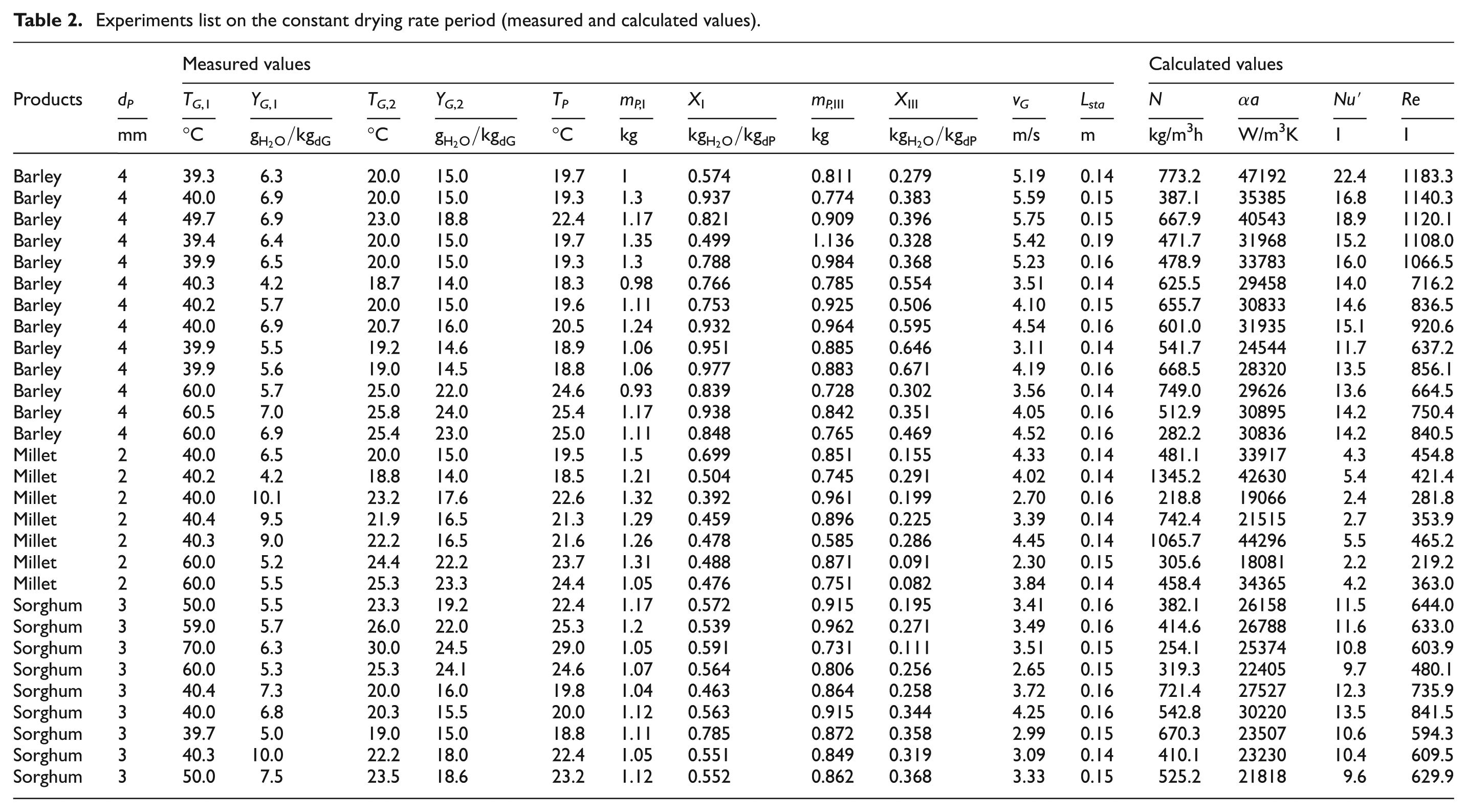
Our measurements were performed with three materials: barley, millet, and sorghum. The air velocity was varied in a wide range of Reynolds numbers between the minimal and maximal fluidization velocity of each material. The main parameters of the measurements in the constant drying rate period, and the calculated values are listed in Table 2. The thermodynamic properties of gas–water system specified by Perry, 29 and the physical properties of analyzed materials were determined with additional examinations in the laboratory.
Experiments list on the constant drying rate period (measured and calculated values).
A volumetric drying rate is applied for each measurement. Based on the initial volume of the loaded material, the volumetric drying rate determines that how many kilograms of water evaporate from the loaded volume of material in the given time
The results of the measurements with three materials (millet, sorghum, and barley) are represented in Figure 5. In case of drying millet particles, the results are in a lower Reynolds number region (219 < Re < 465) because the diameter of particles and the velocity of gas needed for fluidization are lower than in case of drying the other two types of particles. The Reynolds number interval for sorghum was (480 < Re < 842), and it was for barley that the region of the Reynolds number was the highest: 716 < Re < 1183 because barley had the largest particle diameter and the highest gas velocity for fluidization.

Plots of our measurement Nu′ = f(Re).
Evaluation of literature data
We revised the measurement data from some literature sources too. The calculations can be applied only for those studies where the dimensionless equations with their scopes were published, and the measurement conditions and the specifications of the particles were published as well. Another important criterion was that the studies dealt with the case of drying, and the criterial equations were valid for the constant drying rate period. Usually, there was a lack of measurement data available. Publications15–18 were appropriate for reworking their measurement data for the volumetric heat transfer coefficient. All studies were based on the assumption that the particles were spherical with ideal contact between the gas and the particles. During the review, the volumetric heat transfer coefficients were evaluated. In the knowledge of the Nu = f(Re) equations, its scopes, and the range of particle diameters and gas velocities, the heat transfer coefficient can be calculated

Calculation of the specific surface area of particles, knowing the porosity of particles and assuming that the particles are spherical 30

The volumetric heat transfer coefficient can be calculated by multiplying the heat transfer coefficient (10) and the volumetric interfacial surface area (11); afterwards, the modified Nusselt number (8) can be evaluated.
Figure 6 shows the converted measurement points from the literature15–18 together with our results evaluated from the measurements. The revised data using modified Nu′-Re equations show better fit compared to the original values. Using modified Nusselt number gives a more accurate possibility for scaling up fluidized bed dryers because it deals with the real geometry, size and number of particles, than in the case of using the conventional Nusselt number regular geometry and ideal contact between material and air is assumed. The results show proper conformity with literature data and with the results of our measurements using modified Nusselt number.

A trend line was fitted to the measurement points, which shows great correlation. The coefficient of determination to the measurement points is R2 = 0.9153. The error of measurement was calculated to check the measurement accuracy. The value of the modified Nusselt number from our measurements has an error of around 25% caused mostly by the basic measurement error of the instruments. The data of measurement errors reported in literature are unknown; therefore, the same value of margin of error was fitted to these points. Two dashed lines were fitted through the extremities of the margin of errors fitted to the points. The margin of error can be reduced using a volumetric heat transfer coefficient and a modified Nusselt number.
Based on literature data and our measurements, the Nu′ = f(Re) relationship for fluidized bed drying is as follows

Equation (12) is valid on (17 < Re < 1183).
Conclusion
The purpose of our work was to introduce a volumetric heat transfer coefficient for fluidized bed drying to eliminate the uncertainties of determination of the heat transfer surface between the gas and the particles. The modified Nu′ = f(Re) equation showed proper correlation between the results of the measurements in the literature and the results of our measurements. A modified Nu′ = f(Re) relationship was created for fluidized bed drying from the measured volumetric heat transfer coefficients and those reworked from literature. The equation was valid for the region 17 < Re < 1183 on the constant drying rate period. The goal of our work was to propose a new method for scaling up fluidized bed dryers using a volumetric heat transfer coefficient. For further investigations, the diagrams will be supplemented by additional data from the literature and additional measurements will be performed using new types of material to extend the range of validation of the modified Nu′ = f(Re) equation.
Footnotes
Appendix 1
Academic Editor: Hua Meng
Declaration of conflicting interests
The author(s) declared no potential conflicts of interest with respect to the research, authorship, and/or publication of this article.
Funding
The author(s) disclosed receipt of the following financial support for the research, authorship, and/or publication of this article: This article was supported by Gedeon Richter’s Talentum Foundation (H-1103 Budapest, Gyömrői str. 19-21, Hungary) and by Hungarian Scientific Research Found (OTKA-116326).