
Abstract
A permanent magnetic toroidal drive with a half stator is proposed that avoids noise and mechanical vibrations. The effects of the system parameters on the output torque of the drive were investigated. A model machine was designed and produced. The output torque and speed fluctuation of the drive system were measured, and the calculated and measured output torque were compared. The tests demonstrated that the drive system could operate continuously without noise, and the system achieved a given speed ratio. The drive system had high load-carrying ability and a maximum output torque of 0.15 N m when certain parameter values were used.
Introduction
A toroidal drive consists of a central input worm, several radically positioned planets, a stator of toroidal shape, and a rotor. The rotor forms the central output shaft upon which the planets are mounted. The input worm rotates each planet about its own axis. The planets have balls or rollers instead of teeth, and each planet meshes with the toroidal grooves in the stator and the worm. The drive can transmit high torque and is suitable in technical fields such as aviation and space flight. 1 In the 1980s, numerous studies were performed regarding toroidal drive machining technology, tooth profile calculation methods, and load distributions on toroidal drive stators and worms.2–5 More recently, the mesh theory and contact stress of the toroidal drive were investigated.6,7 Later, the meshing characteristics of toroidal drives with different roller shapes were analyzed, the relative motions in a toroidal drive were evaluated, and the friction coefficients between the planets and stator or worm under partial hydrodynamic lubrication were determined.8,9 The pressure angle changes and their effects on toroidal drive operating performance were investigated in one study. 10 The contact stress in a toroidal drive and its changes along with drive parameters were also studied. 11 Recently, a toroidal drive with a half stator was proposed that would enable miniaturization of the toroidal drive. 12 In summary, much research has been conducted on toroidal drives, including their optimal design and manufacturing techniques. However, a toroidal drive system requires high machining accuracy if substantial noise and vibrations caused by poor meshing between teeth are to be avoided.
In this article, a novel design of a toroidal drive with a half stator is proposed. The permanent teeth of the drive, between which meshing occurs, are replaced by magnetic forces that achieve meshing without contact. This design substantially decreases the noise level of the toroidal drive and decreases the machining accuracy required. Additionally, no lubrication oil is required in the no-contact meshing drive. Therefore, the drive can be used in situations requiring low noise and no lubrication oil usage.
The output torque of the proposed toroidal drive was investigated, and a model of the drive system was designed and produced. The maximum output torque and speed fluctuation of the drive were measured. The calculated output torque and measured output torque were compared. The drive system was demonstrated to operate continuously without noise and it achieved a given speed ratio. The drive system had high load-carrying ability and a maximum output torque of 0.15 N m.
Structure of the proposed toroidal drive
The main parameters of the proposed permanent magnetic toroidal drive system are listed in Table 1. Figure 1 presents a schematic diagram of the toroidal drive and its three-dimensional (3D) model. The drive consists of four basic elements: (a) a central input worm made of steel, (b) radically positioned planets whose teeth are made of a permanent magnetic material, (c) a stator of toroidal shape made of steel, and (d) a rotor. The stator is half the size of a normal stator and its face width angle is 90°, which ensures that there are sufficient teeth in mesh between the stator and the planets and enables contactless meshing.
The main mechanical parameters for the toroidal drive with half stator.


Permanent magnetic toroidal drive with half stator: (a) schematic, (b) 3D model, (c) planet model, (d) rotor model, (e) stator model, and (f) worm model.
The contact meshing forces between the teeth of the planets and the worm or stator are replaced by magnetic forces requiring no contact. When the worm rotates, a toroidal circular field is formed that drives the planets to rotate about their axes. The magnetic forces between the teeth of the planets and the stator then drive the rotor to rotate about its own axis. Thus, a power of low speed and high torque is output.
The operating principle of the drive can be demonstrated using a simple example. The parameters of the example drive are as follows: number of worm threads z2 = 1, number of teeth on each planet z1 = 12, and number of teeth on the stator z3 = 35. Three instants are selected to illustrate the operating principle of the drive. At instant 1, the position angle of the worm is 0°. Magnetic flux is produced between the worm and planet teeth and between the planet and stator teeth. Because the stator is fixed, the rotating magnetic field drives the planets to rotate about their axes, which in turn drive the stator to rotate about its axis. At instant 2, the worm has moved by an angle of 180°. This has driven the planets to move by an angle of 30° (=360/12). Because the teeth of the stator are helical, rotation of the planets drives the rotor to move by an angle of 5° [=180/(1 + z3/z1)]. At instant 3, the worm has moved by an angle of 360°. This has driven the planets to move by an angle of 60°. The rotation of the planets has driven the rotor to move by an angle of 10°. Therefore, the speed ratio is 36.
Forces and output torque
A permanent magnetic planet tooth meshes with the teeth of the worm and stator at the planet rotation angle


Forces in the drive system: (a) forces between planet and worm and (b) forces between planet and stator.
Let T denote the torque applied to the rotor. Then

where n is the planet number,
Let
The magnetic energy storage increment W can be given as

where
By substituting equation (5) into equation (4), the magnetic force F is obtained

By means of magnetic theory, the derivative

where z is the air-gap thickness,
Let Br denote the magnetic induction intensity of the permanent planet tooth. The magnetic potential
By substituting equations (7) and (8) into equation (6), and then substituting it and equations (1) and (2) into equation (3), the output torque of the drive system can be obtained.
Using the aforementioned equations, the output torque of the drive system was investigated. The main parameters of the drive are listed in Tables 1 and 2. Figure 3 depicts four drive properties:
As the relative displacement between the two sides of the air gap increases, the output torque of the drive system first increases significantly, reaches a maximum value, and then decreases gradually. The maximum output torque represents the limited load-carrying ability of the drive and was here equal to 0.3 N m. It is also related to the magnetic induction intensity of the permanent planet teeth, the air-gap thickness, and other drive parameters such as the center distance and planet radius.
If the air-gap thickness between two elements in mesh is increased, the output torque of the drive system decreases substantially. At z = 0.1 mm, the output torque is nearly 0.7 N m, which is two times greater than that at z = 0.5 mm. If the air-gap thickness is larger than 1 mm, the output torque is quite low, and the system nearly loses its load-carrying ability. Therefore, the air-gap thickness between two elements in mesh should be designed to be as small as possible.
If the center distance between the planet and the stator is increased, the output torque of the drive increases significantly. This is because increasing the center distance causes the magnetic force arm to increase. If the planet radius is increased, the output torque of the drive increases significantly because the increase in the planet radius causes an increase in the magnetic force arm. The drive’s output torque reaches a maximum for a certain planet radius, and if the planet radius is increased beyond this maximum, the output torque decreases. This is because the derivative
The size a + R defines the volume of the drive system. If a + R is constant, the output torque is determined by the ratio a/R. When a/R increases, the output torque slightly decreases. At a/R = 1.5, the output torque is approximately two times greater than the output torque when a/R = 1.5.
Other parameters of the drive system.


Changes of output torque along with system parameters: (a)
Therefore, maximum output torque is obtained when the air-gap thickness between two elements in mesh is as small as possible. Because of the limits of machining precision, the achievable air-gap thickness is 0.05–0.1 mm. Additionally, a large center distance produces high output torque. Under the condition of a constant drive size (a + R = constant), the ratio a/R = 1.5 corresponds to the maximum output torque.
Test
To illustrate the analysis in section “Forces and output torque,” a model of the toroidal drive was designed and produced. The main parameters of the model machine are listed in Tables 1 and 2. Photographs of the main elements of the model machine are presented in Figure 4. After mounting the model machine and the measuring system, the motor was started and the model machine was operated continuously. No noise was heard, which demonstrated that the principal test was passed. Figure 5(a) illustrates the model machine and its test apparatus, including the model machine, a dynamometer, and its drive system. Figure 5(b) illustrates the speed of the model machine’s output shaft, showing that the speed fluctuated during the operation of the machine. This speed fluctuation was caused by changes in the number of teeth involved in the meshing. The speed fluctuation was discovered to be small (less than 2.5%). These results demonstrated operating stability of the drive system.

Photographs of the model machine: (a) worm, (b) stator, (c) planets, and (d) rotor.

Test of the model machine.
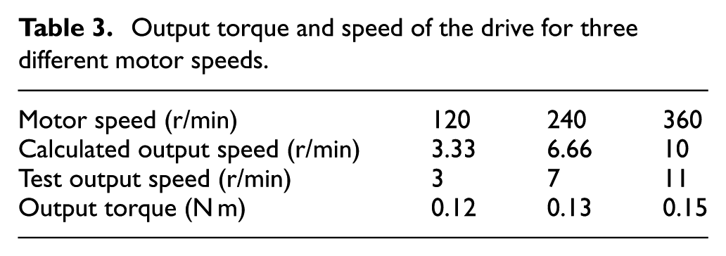
Three motor speeds were tested, and the measured rotational speed and maximum output torque of the model machine are presented in Table 3. A speed ratio of 36 was achieved for the three motor speeds. The output torque of the drive increased gradually when the speed of the motor was increased. When the speed of the motor was tuned to 360 r/min, the maximum output torque reached 0.15 N m, half the previously calculated value (0.3 N m). Therefore, an adjustment to the equation given, for example multiplication by a correction factor (0.5), should be made to correct for the drive’s practical application.
Output torque and speed of the drive for three different motor speeds.
In order to illustrate calculative results of the torque, a finite element analysis software Maxwell is used. Using the parameters in Table 1, the finite element model of the drive system is given. Using the model, the magnetic induction intensity of the drive system is simulated (see Figure 6). Based on it, the magnetic force applied to each planet tooth can be determined. The tangent components of the magnetic forces are multiplied by the radius for the planet tooth on the rotor and summed to obtain the output torque of the drive system (it is about 0.17 N m and near to test result).

Magnetic induction intensity distribution of the drive system: (a) planet and (b) drive system.
Conclusion
In this article, a permanent magnetic toroidal drive with a half stator is proposed. The effects of the system parameters on the output torque were investigated. A model machine was designed and produced. The output torque and speed fluctuation of the drive system were measured, and the calculated output torque and measured output torque were compared. The tests demonstrated the following:
When the center distance between the planet and the stator was increased, or when the planet radius was increased, the output torque of the drive system increased significantly.
The drive system could operate continuously without noise, and the system achieved a given speed ratio. The drive system had a high load-carrying ability and a maximum output torque of 0.15 N m when certain parameter values were used.
Footnotes
Academic Editor: Teen-Hang Meen
Declaration of conflicting interests
The author(s) declared no potential conflicts of interest with respect to the research, authorship, and/or publication of this article.
Funding
The author(s) disclosed receipt of the following financial support for the research, authorship, and/or publication of this article: This project was supported by National Enterprise Technology Innovation Foundation of China (No. 13C26211300471).