
Abstract
The toroidal drive can transmit large torque. However, it is a hard work to produce small toroidal stator which limits the miniaturization of the toroidal drive. Here, a novel toroidal drive with half stator is proposed for which the small stator can be produced easily. For the novel toroidal drive, three-dimensional design and the motion simulation are done; the forces and the contact stress in drive system are investigated; and the output torque is compared with one of the normal toroidal drives. Results show that the output torque of the toroidal drive with half stator is almost the same as the output torque of the normal toroidal drive, and the half stator toroidal drive is a good design for realizing the miniaturization of the toroidal drive.
Introduction
In 1966, the toroidal drive was proposed which consists of four basic elements: (a) the central input worm; (b) radically positioned planets; (c) a stator of toroidal shape; and (d) a rotor, which forms the central output shaft upon which the planets are mounted. The input worm rotates each planet about its own axis. The planets have balls or rollers instead of teeth. Each planet meshes with the toroidal grooves in the stator and the worm. The rotor is the output. 1 The drive can transmit large torque and is suitable for the technical fields such as aviation and space flight.
In 1981, a model machine of the toroidal drive was produced. 2 In 1983, a calculation method for the tooth profile of the stator was proposed. 3 In 1984–1985, pitting problems on stator surface and the load distributions on stator and worm were investigated.4,5 In 2003–2004, the mesh theory and the contact stress of the toroidal drive were investigated.6,7 In 2006, the meshing characteristics of the toroidal drive with different roller shapes were analyzed. 8 In 2007, the relative motions for the toroidal drive were analyzed and the friction coefficients between the planet and the stator or the worm under partial hydrodynamic lubrication were determined. 9 In 2010, the pressure angle changes and its effects on the toroidal drive’s operating performance were investigated. 10 In 2013, the contact stress in the toroidal drive and its changes along with drive parameters were studied. 11
In a word, a lot of studies about the toroidal drive were done which include design theories and manufacturing techniques. However, it is a hard work to produce a small toroidal stator. Here, the milling cutter had to be placed inside the stator which limits the sizes of the stator produced, and the miniaturization of the toroidal drive is quite difficult. Besides it, to produce the stator, the thickness of the stator had to be taken to be quite small; it reduces the tooth number in mesh between the stator and the planets.
In this article, we proposed a novel design of the toroidal drive: the toroidal drive with half stator in which a small stator can be produced easily. It makes the miniaturization of the toroidal drive possible which is more suitable for the fields requiring small size and weight such as aeronautics and astronautics. It expands knowledge about structure form and load-carrying ability of the toroidal drive. For the toroidal drive with half stator, three-dimensional (3D) design and the motion simulation were done; the forces and the contact stress in the drive system were investigated; and the output torque was compared with one of the normal toroidal drives. Results show that the output torque of the toroidal drive with half stator is almost the same as the output torque of the normal toroidal drive. It is not possible to produce a quite small stator of the normal toroidal drive, and it is easy to produce one of the same small sizes for the toroidal drive with half stator. Hence, the research is important to realize the miniaturization of the toroidal drive. Of course, compared with the normal toroidal drive, the structure of the half stator toroidal drive is not symmetrical which causes a relatively large axial load acting on the bearing of the output shaft.
Design of the toroidal drive with half stator
Figure 1 shows the proposed toroidal drive with half stator. It also consists of four basic elements: (a) the central input worm; (b) radically positioned planets; (c) a stator of toroidal shape; and (d) a rotor. However, the stator is the half of the normal stator and its face width angle is 90° which can ensure enough tooth number in mesh between the stator and the planets. This design makes it easy to produce a small stator. It makes the miniaturization of the toroidal drive possible.

Toroidal drive with half stator: (a) diagram of the drive and (b) 3D model of the drive.
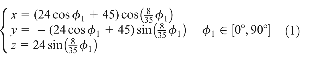
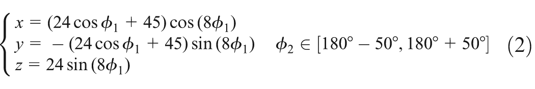
The teeth of the stator and worm are cut on the toroidal surface of the stator or worm blank, among which the teeth of the stator are cut on the internal toroidal surface, so it is difficult to construct their 3D models. Their basis is calculation of the pattern curves. In planet coordinate system, the center of the planet tooth can be calculated easily. If the center of the planet tooth is transformed to stator coordinate system, the center of the stator tooth can be given. If the center of the planet tooth is transformed to worm coordinate system, the center of the helical tooth for worm can be given as well. The center equation of the stator tooth is
The center equation of the worm tooth is
Thus, the pattern curves of the stator and worm teeth are obtained. Based on center curve of the teeth, in the environment of the Pro/Engineer software package, the 3D stator and worm models can be constructed. It is indicated as follows:
Built stator and worm blanks. Based on the given design parameters (the main parameters of the drive are shown in Table 1), some main dimensions of the toroidal drive are drawn in an outline sketch. Then, by means of the command “Rotate,” a solid stator or worm blank is created.
Built a sweep path. By means of the command “Insert base curve,” the sweep curve can be created from tooth center equations.
A single stator or worm tooth. The tooth cross section of the stator and worm is taken as a trapezoid perpendicular to the center curve of the stator tooth. Applying a command “helical sweep” in the environment of the Pro/Engineer software package and going through the above trapezoid cross section, a single stator and worm helix tooth are created.
The whole stator or worm model. Applying a command “Pattern,” the above single stator or worm tooth is patterned into several teeth arrayed evenly in the radial direction, and the 3D stator or worm model is constructed (see Figure 2(a) and (b)).
3D planet model. Construction of the 3D planet model does not involve curve pattern and can be created easily (see Figure 2(c)).
The solid model for the drive. In the environment of the Pro/Engineer software package, several “Assembly” commands are given, and the above stator, worm, and planets are placed and assembled together with rotor, and the solid model for the drive is created (see Figure 2(d) and (e)).
Main parameters for the toroidal drive with half stator.


3D model of the drive and its main components: (a) stator; (b) worm; (c) planet; (d) 3D model of the drive; and (e) perspective model of the drive.
Using the 3D model of the drive system, the motion simulation of the drive is done as follows:
The stator and the planet are defined as gear pair 1, and the worm and the planet are defined as gear pair 2.
The worm shaft is defined as the input shaft where a motor is defined and its rotating speed and direction are also defined.
Using the mechanism analysis model, the analysis time is defined and the motion video is output.
Global collision test is done where the motion collision does not occurs which shows that the design of the drive system is correct.
Force and stress
A ball planet tooth is meshing with the stator at the planet rotating angle
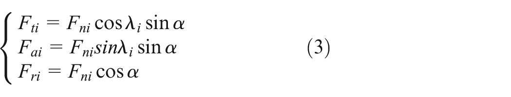
where

Forces on the toroidal drive and deformation coordination: (a) forces and (b) deformation coordination.
Let

where
From Figure 3, the deformation coordination equation can be given as

Combining equation (5) with equations (3) and (4), the normal force between the planet and the stator can be obtained

In the same manner as equation (6),

where
Substituting equations (6) and (7) into Hertz equation, the contact stress between the planet and stator or worm can be given

where
Results and discussion
Using the above-mentioned equations, the contact stress distributions between the planet and stator or worm are investigated (see Figures 4 and 5). The main parameters of the drive are given in Table 1. Figures 4 and 5 show the following:

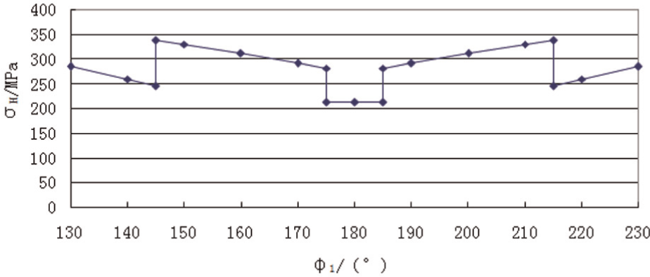
Contact stress distribution on the stator.
Contact stress distribution on the worm.
There are abrupt changes in contact stress of the stator which is because there are abrupt changes in the tooth pair number in mesh. Here, there are two tooth pairs in mesh at the angle range
The contact stress in the angle range
At the angle range
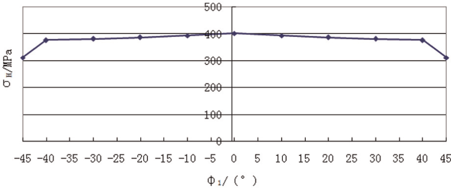
There are also abrupt changes in contact stress of the worm which is because there are abrupt changes in the tooth pair number in mesh as well. Here, there are two tooth pairs in mesh at the angle ranges
The contact stress distribution is symmetrical to angle position 180°. In two symmetrical angle ranges, the contact stress decreases gradually when the angle reaches toward angle position 180°. The maximum contact stress occurs at angle
For a normal toroidal drive with the same parameters as ones in Table 1, the contact stress distribution on the stator is calculated (see Figure 6).
Contact stress distribution on the stator for normal toroidal drive.
Compared with the stress distribution of the half stator toroidal drive, the different points are that the contact stress distribution of the normal toroidal drive is symmetrical to angle position 0°, and the maximum contact stress occurs at angle
For a same output torque (here it is 7365 N m), the maximum contact stress is
If the same maximum contact stress is given
Such a small size of the normal toroidal drive cannot be produced. However, the same size of the half stator toroidal drive can be produced easily though the output torque of the half stator toroidal drive is a bit smaller than that of the normal toroidal drive. Therefore, the half stator toroidal drive is a good design for realizing the miniaturization of the toroidal drive.
Finite element method simulations
Here, a finite element method (FEM) analysis package, ANSYS, is used to simulate contact stress of the toroidal drive with half stator. Parameters of the example drive system are same as in Table 1. Figure 7 shows FEM model and mesh-dividing pattern of the drive system. The element number of the FEM is 113069, and the node number is 286840. Here, stator, worm, planet, and rotor are made of steel. In this analysis, the modulus of the elasticity of the steel is 206 GPa and Poisson’s ratio is 0.3. The boundary conditions for the drive system are as follows: the stator is fixed, and the worm and the rotor are given rotating degree of freedom.

Mesh-dividing pattern.
By the above FEM model and boundary conditions, the stress distributions in a toroidal drive with half stator are investigated (here, worm torque T
1 = 205 N m and rotor torque T
2 = 7365 N m). Under the same conditions, comparison of the calculative values and FEM simulation results about the maximum contact stress on the stator and the worm is completed (see Tables 2 and 3). Figure 8 shows the stress distribution in the worm and the stator for the position angle
Comparison of stator

FEM: finite element method.
Comparison of worm
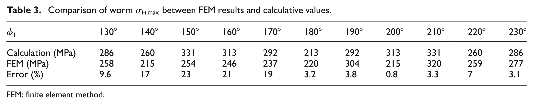
FEM: finite element method.

(a) Stress distribution in the stator and (b) stress distribution in the worm.
From Tables 2 and 3 and Figure 8, it is known that the maximum contact stress of the drive system occurs on the stator. The calculative error of the maximum contact stress on the stator is smaller than 11%. The calculative error of the maximum contact stress on the worm is smaller than 23%. It illustrates the calculative results given in the article.
In a toroidal drive, the elastic deformation occurs in the bearing of the planets. The bearing is equivalent to the cantilever beam. In the part away from the output shaft, the elastic deformation is relatively large. It just corresponds to 80° for the stator and 150° for the worm. Here, the relatively large elastic deformation of the bearing causes decrease in the contacting forces between the planet teeth and stator or worm.
In FEM analysis, the elastic deformation is considered. In calculative values, the elastic deformation is not considered. So, the high error values occur around 80° for the stator and near 150° for the worm. Around 230°, the elastic deformation of the bearing is the minimum, so the low error values occur.
Conclusion
In this article, the toroidal drive with half stator is proposed. For the drive system, 3D design and the motion simulation are obtained; the forces and the contact stress are investigated; and the output torque is compared with one of the normal toroidal drives. Results show the following:
The maximum stress occurs on the stator. The calculative error of the maximum contact stress is smaller than 11%.
The output torque of the toroidal drive with half stator is almost the same as the output torque of the normal toroidal drive.
It is easy to produce a small stator of the toroidal drive with half stator. The half stator toroidal drive is a good design for realizing the miniaturization of the toroidal drive.
Footnotes
Academic Editor: Yong Chen
Declaration of conflicting interests
The authors declare that there is no conflict of interest.
Funding
This project was supported by the National Enterprise Technology Innovation Foundation of China (no. 13C26211300471).