
Abstract
This article describes the configuration and working principle of the high-temperature combustion system; according to the control requirements which have a wide range and high precision for fuel flow-rate of the high-temperature combustion system, a set of fuel supply system is designed based on the frequency conversion hydraulic technology and electro-hydraulic proportional technique. An automatic control system with the function of field and remote control is carried out to achieve the precise supply of the fuel. The transfer function which describes the dynamic characteristic of the fuel supply system is given and the dynamic matrix control algorithm is employed to realize the high-quality control of fuel flow-rate. The experimental results show that the response time of flow-rate is about 12 s, almost no overshoot, and control accuracy within 1%. Therefore, the designed fuel supply system can meet the requirements of the high-temperature combustion system, and the designed control system has good control performance.
Keywords
Introduction
High-temperature combustion system (HTCS) is used to produce a gas flow field which has a characteristic of high speed and high temperature, and the heated situation of the specimen in the actual work situation can be simulated. 1 Its working principle is that it takes aviation kerosene as the fuel and high-speed air stream as the accelerant, a high-temperature jet stream is obtained by the combustion of kerosene in the combustor, and a homogeneous temperature distribution in the experimental section of combustor is formed, so the desired test can be performed. Therefore, a homogeneous temperature distribution is a direct performance index reflecting the advantages and disadvantages of the HTCS. In a practical work process, first, the mass flow-rate of air is determined, and then the gas temperature is controlled according to the fuel flow-rate, so the gas temperature of HTCS is mainly determined by the fuel flow-rate which is supplied to the combustor. As long as the fuel flow-rate is controlled accurately, the gas temperature can be controlled precisely. Therefore, designing a wide range of fuel supply system and realizing the accurate control of the fuel flow-rate are the basic conditions that ensure the performance of the HTCS.
Three methods are generally used to achieve the regulation of fuel flow-rate; they are throttle valve control, variable displacement pump control, and variable frequency driving motor-pump control. The third method has many advantages, such as lower cost, simple structure, better energy saving effect, and wide speed regulation range. 2 Therefore, it has been widely applied and researched. In 1988, Nakano and Tanaka 3 applied the variable frequency drive technology to the hydraulic system and realized the constant pressure control. In 1989 and 1991, they studied the dynamic and static characteristics of a variable frequency hydraulic constant pressure system with accumulator.4,5 Wu and Lee 6 carried out simulation and experimental research on the variable frequency pump control motor and pump control motor system using adaptive control method. The simulation of the variable frequency motor drive quantitative pump system was carried out, and the coordinated control of the inverter and proportional directional valve was realized by Manasek. 7 Peng 8 set up the mathematical model of variable frequency pump control motor system and studied the system by using proportional–integral–derivative (PID) algorithm, fuzzy algorithm, neuron algorithm, and genetic algorithm. In this article, a fuel supply system based on variable frequency hydraulic technology and electro-hydraulic proportional technology was designed because the fuel flow-rate was needed to adjust in a larger range.
There are few related literatures about fuel flow-rate control. Li et al. 9 used a pulse-and-gliding control strategy to minimize fuel consumption in automated car. A flow-rate control based on variable frequency technology for a high-temperature variable displacement pump was carried out by Xu et al. 10 To achieve the accurate closed-loop control of fuel flow-rate, a fuzzy PID algorithm was used by Zhang and Li, 11 but the authors did not consider the large inertia and pure lag caused by the gear flowmeter. Aiming at the problem of large inertia and pure lag caused by gear flowmeter, a PID control strategy with Smith predictor was used by Liu et al., 12 but Smith estimation needs accurate mathematical model.
Working principle of the HTCS
HTCS includes gas supply subsystem, gas generator, fuel supply subsystem, test section, specimen, and its support equipment, gas exhaust subsystem, monitoring, and control system. The configuration of the HTCS is shown in Figure 1. In the experiments, first, the fuel supply system provides predetermined aviation kerosene, then the fuel was burnt in the primary and secondary combustor of gas generator, and a central flame and annular flame is formed. Thus, high-speed airflow which is provided by the gas supply subsystem can be heated to 500–2100 K. The simulation of high temperature and large heat flux in the stagnation region of the specimen (such as supersonic aircraft’s nose cone, wing leading edge) can be achieved by acting the hot gas on the specimen. Monitoring and control system is responsible for monitoring the entire system and controlling the operation of each subsystem according to the test process, for example, give the expected flow-rate instructions of the fuel supply subsystem.

The configuration of the HTCS.
The main work of this article is to develop the fuel supply subsystem of the HTCS. As described above, the task of the fuel supply subsystem is to provide the required and cleanliness aviation kerosene for the gas generator of the HTCS; it is one of the most important subsystems of the HTCS, which directly affects the heating effect of high-temperature gas and the entire test. The fuel supply subsystem is needed to meet many requirements, such as automatic precise control, wide range of fuel supply, easy to operate, and security. In addition, it is also required to be as a relatively independent subsystem and can be easily integrated into the overall system.
Design of the fuel supply system
The overall design of the system
According to the technical index and operating requirements of the fuel supply system, the structure diagram of the system is obtained, and it is shown in Figure 2. It is made up of three parts: supply system, refueling system, and control system. The supply system is used to supply the fuel to the combustor and ignition of the gas generator; the refueling system is used to inject kerosene to the tank of the supply system; the control system is used to control start–stop of the pumps in the supply system and the refueling system, and to realize the flow regulation, alarm processing, liquid level control, and so on.

Structure diagram of the fuel supply system.
Figure 3 shows the working principle of the fuel supply system. The relationship among the refueling system, the supply system, and the control system can be obtained from the figure. The supply system is composed of frequency converter, motor, pump, proportional valve, pipeline, valve groups, gear flowmeter, fuel supply tank, and so on. It is composed of the ignition circuit and the supply circuit and provides the stipulated flow-rate of aviation kerosene to the combustor of the HTCS independently. The supply system will start to supply the fuel and the ignition fuel circuit will be cut off after the ignition success. The refueling system is composed of fuel refueling tank, motor, and pump, the role of which is to add fuel to the fuel supply tank. The control system takes programmable logic controller (PLC) as the field controller and industrial control computer as the remote controller. Fuel flow-rate signals are obtained by the flowmeter and are delivered directly to the PLC, and it can also be transmitted to the industrial control computer by RS485 bus. Taking into account the limited computing ability of PLC, the specific control algorithm can be implemented on industrial control computer, and then the control commands will be sent to PLC; PLC will change the flow-rate of the system by control frequency converter or proportional throttle valve, so the closed-loop control of the fuel flow-rate of the whole system can be realized.

Working principle of fuel supply system.
Hydraulic principle of the fuel supply system
Due to the fact that there are many types of HTCS, the requirement of fuel flow-rate varies with the gas temperature requirement of the HTCS. Combined with the requirement of gas temperature for each HTCS, it can be known that the gas temperature range of the HTCS is about 227°C–1827°C, and the fuel flow-rate range corresponds to 0.2–7 L/min. A kind of composite flow-rate regulation scheme was adopted when the fuel supply system is designed according to the wide fuel flow-rate range. That is, when the demand of the flow-rate is large, the variable frequency pump is used to adjust the flow-rate, and when the demand of the flow-rate is small, the bypass proportional throttle valve is used to adjust the flow-rate. The hydraulic principle of the fuel supply system designed in this article can be seen in Figure 4. From Figure 4, it can be seen that the hydraulic system is composed of two separate fuel circuits, the primary fuel circuit and secondary fuel circuit, which can be divided into two circuits to provide fuel to the combustor of three sets of HTCS. Each fuel circuit includes manual stop valve, pressure gauge, pump, check valve, electromagnetic relief valve, solenoid valve, electro-hydraulic proportional throttle valve, fuel tank, flowmeter, pressure sensors, filter, and so on. The working principle and control process of the two fuel circuits are basically the same. When the expected flow-rate is greater than or equal to 1.5 L/min, it closes the bypass proportional throttle valve, only by adjusting the rotational speed of the pump to achieve flow-rate control; when the expected flow-rate is less than 1.5 L/min, it fixes the pump at a certain speed, by adjusting the opening of the bypass proportional throttle valve to realize flow-rate adjustment. Because the frequency converter and the proportional valve have a larger adjustment range and higher resolution, and coupled with the flow-rate closed-loop compensation, a precise control of wide range for the two circuits’ flow-rate can be carried out.

Hydraulic principle diagram of fuel supply system.
Control system design
The fuel control system designed in this article consists of the field control system and the remote control system. The function of the field control system is to realize the signals’ acquisition, such as flow-rate, pressure, and other data, and the field operation of the system. The remote control system is mainly used to realize the remote operation and the development of control algorithm.
Due to the harsh environment and serious interference of the HTCS, this article chooses PLC which has strong anti-interference performance as the field controller. In this system, the main function of PLC electric control system is to realize the starting and stopping of the fuel supply system, system status monitoring, the alarm, and precise control of the fuel flow-rate. The model of PLC used in this system is Siemens S7-200, because this system deals the signal quantity is large; when the system is designed, many PLC modules are required. The selected PLC modules contain a CPU226 main module, two pieces of EM222 relay output module, one piece of EM223 digital input/output (I/O) module, two pieces of analog input module, and two pieces of EM232 analog output module. According to the function of the fuel supply system and the selection of the hardware to complete the production of the field control system, the field control cabinet which is designed in this article is shown in Figure 5.

The field control cabinet.
There are many merits in PLC control system, such as strong anti-interference ability, easy to implement, flexible design, higher reliability, and high cost performance. 13 But it also has weaknesses. The first one is that the man–machine interface is mainly composed of buttons, switches, indicator lights, and so on; it cannot display various data curves in real-time, and the other is that the programming ability of PLC is limited, which cannot use it to realize complex control algorithm. Therefore, on the basis of the development of the field control system, this article developed a remote computer control system to inherit and expand the function of PLC. In this article, a remote control system of the HTCS is developed on the MFC platform using VC++ as a development language. The main control interface of the remote control system is shown in Figure 6.

The master interface of the remote control system.
The model of the fuel supply system
When setting up the mathematical model of the system, two cases should be discussed separately because there are two different operating modes of the fuel supply system, one is the variable frequency pump control mode and the other is the bypass proportional valve control mode. In the first operating mode, the fuel supply system is mainly composed of frequency converter, motor, quantitative pump, and pipeline; the bypass proportional valve does not work. Transfer function from the control voltage of the frequency converter to the fuel flow-rate can be obtained by referring the literature 14

where
In the second operating mode, the speed of the quantitative pump is fixed; the fuel flow-rate is controlled through proportional valve. The transfer function from the input voltage

where
The overall transfer function of the fuel supply system in two operating modes can be obtained by combining equations (1) and (2). It can be expressed as

The actual fuel flow-rate

Control strategies and experiment
Control strategy of the fuel flow-rate
Because the pipeline of the fuel supply system is long and gear flowmeter brings a large inertia and lag in the actual control system, the system is a typical time delay system, and the existence of time delay can bring trouble to the precise control of the fuel flow-rate. In addition, the fuel supply system designed in this article can supply fuel to three different sets of HTCS, and the characteristics of each HTCS are diverse. The difference mainly displays in the pressure of the inlet fuel nozzle, which causes the difference in the load when the fuel supply system provides fuel for different HTCSs, so that the parameters of the mathematical model can be changed. At the same time, under different working conditions of the same HTCS, the load of the system will also change with Mach number, so the model parameters of the system can be changed. Therefore, the mathematical model of the system has time-varying parameters, which are not easy to control. The above two characteristics of the fuel supply system increase the control difficulty of the system and the use of simple PID control is difficult to get satisfactory effect.
Dynamic matrix control (DMC) is a predictive control algorithm based on the step response of the controlled object to describe the dynamic model of the system, which is suitable for the industrial process with the characteristics of large lag, strong coupling, uncertainty, and multi-variable, and the accurate mathematical model of the system is difficult to establish. It has been successfully applied in the control system of petroleum, paper manufacturing, electric power, chemical, metallurgy, and other industrial departments for the advantages of simple algorithm, small amount of computation, strong robustness, and so on. 16 Therefore, this article selects the DMC as the controller.
The control law of DMC includes model prediction, rolling optimization, and feedback correction.
17
The function of model prediction is to predict the output of the model in the future. When the model prediction is carried out, the first step is to obtain the sampling values

where

The function of rolling optimization is to obtain
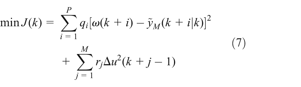
where q and r are the weighting coefficients.

The role of feedback correction is to correct the model, and it can be achieved through the following steps. First, get the first element of

The corrected values of prediction can be expressed as

where
Experiment
In this article, experimental study on fuel flow-rate of HTCS was conducted based on the designed control system and control method. According to the description of the previous section, the fuel supply system which is designed in this article has two operation modes, one is the variable frequency pump control mode and the other is the bypass proportional valve control mode. In the variable frequency pump control mode, closing the bypass proportional valve, the control of the fuel flow-rate is realized by adjusting the speed of the pump; in the bypass proportional valve control mode, fixing the speed of the pump, the control of the fuel flow-rate is realized by adjusting the opening of the proportional valve. To simplify the problem and verify the effectiveness of the control algorithm, the first operation mode is adopted in the experiment. In the experiment, first, the fuel flow-rate should be stabilized at 2.0 L/min, and then the flow-rate is set to 2.5 L/min, so a step response experiment of the flow-rate from 2.0 to 2.5 L/min is completed. The experimental results can be seen in Figure 7. The experimental results show that the system has a certain time delay; this shows that the lag analysis of the system is correct. The results also show that the response time of the system is about 12 s and almost no overshoot, and control precision is within 1%. Therefore, the fuel supply system which is designed in this article can realize the accurate control of the fuel flow-rate and meet the requirement of the HTCS.

Experimental result of fuel flow-rate control.
Conclusion
First, a set of automatic control system for the fuel flow-rate control of the HTCS was designed in this article for the actual problems existing in the fuel flow-rate control of the HTCS and the control requirements of the fuel flow-rate. Then mathematical model of the system was given, and the DMC law was adopted as the fuel flow-rate controller on the basis of the dynamic property of the fuel supply system. Finally, experimental study on the control of the fuel flow-rate using the DMC law was conducted. The experimental results showed that the response time of the systemic flow-rate is about 12 s and almost no overshoot, and control precision is within 1%, so the control algorithm has good performance and realized the accurate control of fuel flow-rate and achieved a satisfactory control effect.
Footnotes
Academic Editor: Jiin-Yuh Jang
Declaration of conflicting interests
The author(s) declared no potential conflicts of interest with respect to the research, authorship, and/or publication of this article.
Funding
The author(s) disclosed receipt of the following financial support for the research, authorship, and/or publication of this article: This work was supported by National Key Basic Research Program of China under grant no. 2014CB046403, Natural Science Foundation of China under grant no. 51475019, and the Nature Science Foundation of Hebei Province grant no. F2015402114 and no. E2014402047.