
Abstract
Many research studies have shown that low temperature combustion in compression ignition engines has the ability to yield ultra-low NOx and soot emissions while maintaining high thermal efficiency. To achieve low temperature combustion, sufficient mixing time between the fuel and air in a globally dilute environment is required, thereby avoiding fuel-rich regions and reducing peak combustion temperatures, which significantly reduces soot and NOx formation, respectively. It has been demonstrated that achieving low temperature combustion with diesel fuel over a wide range of conditions is difficult because of its properties, namely, low volatility and high chemical reactivity. On the contrary, gasoline has a high volatility and low chemical reactivity, meaning it is easier to achieve the amount of premixing time required prior to autoignition to achieve low temperature combustion. In order to achieve low temperature combustion while meeting other constraints, such as low pressure rise rates and maintaining control over the timing of combustion, in-cylinder fuel stratification has been widely investigated for gasoline low temperature combustion engines. The level of fuel stratification is, in reality, a continuum ranging from fully premixed (i.e. homogeneous charge of fuel and air) to heavily stratified, heterogeneous operation, such as diesel combustion. However, to illustrate the impact of fuel stratification on gasoline compression ignition, the authors have identified three representative operating strategies: partial, moderate, and heavy fuel stratification. Thus, this article provides an overview and perspective of the current research efforts to develop engine operating strategies for achieving gasoline low temperature combustion in a compression ignition engine via fuel stratification. In this study, computational fluid dynamics modeling of the in-cylinder processes during the closed valve portion of the cycle was used to illustrate the opportunities and challenges associated with the various fuel stratification levels.
Keywords
Introduction
Low temperature combustion—opportunities and challenges
In an effort to reduce NOx and soot emissions in-cylinder while maintaining high thermal efficiency, many new compression ignition combustion strategies have been proposed. The vast majority of these combustion concepts can be classified as low temperature combustion (LTC). The concept of LTC is best illustrated on a local equivalence ratio (Φ) versus local temperature diagram, as shown in Figure 1(a). This diagram shows the local conditions that produce high NOx and soot formation rates, which were adapted from Kitamura et al. 1 These regions were developed from homogeneous reactor simulations coupled with a detailed soot formation model using n-heptane as the fuel at a pressure of 60 bar and duration of 2 ms, which is a relevant timescale for internal combustion engines. Note that Kitamura et al. 1 have shown that the size and shape of the soot formation region is fuel dependent. Throughout this article, the soot formation island for n-heptane will be used to describe the sooting tendency, in a qualitative sense, of a given combustion mode. The NOx formation region is not fuel dependent. Because of the heterogeneous nature (i.e. wide range of equivalence ratios) of conventional diesel combustion (CDC), NOx and soot formation rates are relatively high. Figure 1(b) illustrates the physical locations within a reacting diesel spray where NOx and soot emissions are formed. NOx emissions are formed near stoichiometric regions where temperatures are the highest, which is at the periphery of the diffusion flame. Soot emissions are formed in the core of the jet where the equivalence ratios are high and the temperatures are modest.
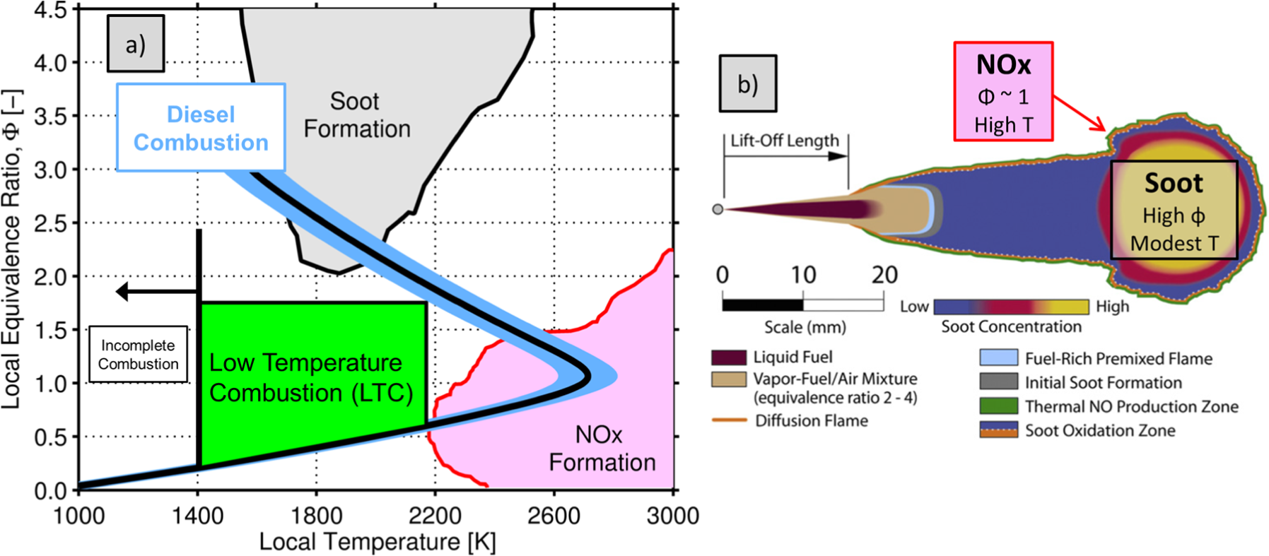
(a) Regions of NOx and soot formation in local equivalence ratio (Φ) versus local temperature space. NOx and soot islands from Kitamura et al. 1 are based on chemical kinetic simulations of n-heptane. (b) Conceptual model of mixing limited diesel combustion illustrating the locations of NOx and soot formation. 2
Simply speaking, the goal of LTC is to achieve sufficient premixing between the fuel and air in a globally dilute environment, such that combustion takes place at lower temperatures, as illustrated in Figure 1. Providing time for fuel/air mixing avoids high soot formation rates. Dilution, with either air or exhaust gas recirculation (EGR), reduces the peak combustion temperatures to avoid high NOx formation rates. However, if the fuel and air are overly mixed, resulting in equivalence ratios that are too low, the local combustion temperature becomes too low to support complete fuel oxidation. Although LTC can yield high thermal efficiency with simultaneously low NOx and soot emissions, there are challenges associated with combustion efficiency (i.e. unburned hydrocarbon (UHC) and CO emissions), narrow operable load range, high pressure rise rates, and combustion timing controllability, all of which in-cylinder fuel stratification aim to address while maintaining low NOx and soot emissions.
There are a number operating strategies for achieving LTC with both gasoline and diesel fuel. Figure 2 illustrates conceptually the landscape of LTC injection strategies for both gasoline and diesel fuel. The strategies are arranged by their level of fuel stratification relative to CDC. The main focus of this article is to provide a review and perspective on the gasoline LTC strategies, namely, partial fuel stratification (PFS), moderate fuel stratification (MFS), and heavy fuel stratification (HFS). For the sake of brevity, the other LTC strategies will not be discussed. For more details on these strategies, please refer to the following publications: reactivity controlled compression ignition (RCCI), 3 diesel premixed charge compression ignition (PCCI), 4 and homogeneous charge compression ignition (HCCI). 5 These references are to serve as examples of these operating modes. There is a significant amount of literature available on these strategies that is not included here.
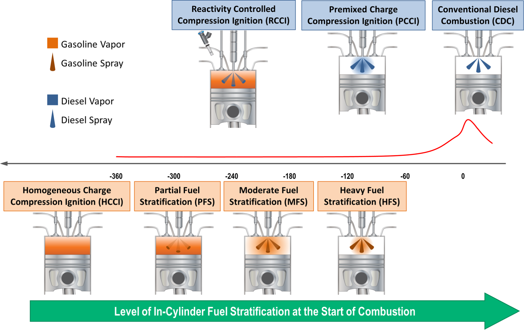
Landscape of advanced compression ignition combustion strategies aimed at achieving low temperature combustion with gasoline and diesel fuel. Strategies are positioned according to the level of fuel stratification at the start of combustion relative to conventional diesel combustion, which is highly stratified.
LTC operability and fuel properties: gasoline and diesel fuel
Gasoline and diesel fuel are both petroleum-derived liquids that come from the fractional distillation and refining of crude oil. Gasoline is a light distillate, and diesel fuel is a middle distillate. With regard to LTC operability, fuel volatility and chemical reactivity (i.e. propensity for autoignition expressed as octane or cetane number) are critical to the in-cylinder processes. In this work, volatility refers to the complete distillation curve and not simply the Reid vapor pressure. Gasoline fuels are more volatile than diesel fuel, meaning they evaporate more readily and at lower temperatures. The boiling ranges for gasoline and diesel fuel are approximately 20 °C–160 °C and 160 °C–380 °C, respectively. 6 The increased volatility of gasoline-like fuels means they will more readily create a premixed charge of fuel and air for either port fuel injection or early direct injection. Perhaps, an even more important fuel property for LTC operability is chemical reactivity or autoignition quality. Gasoline-like fuels are typically composed of relatively small (i.e. carbon number in the range of 5–10) branched or cyclic hydrocarbons. These molecular structures have high bond strength and thus low chemical reactivity (e.g. high octane number). 7 On the contrary, diesel fuels are highly reactive due to the long, saturated molecular structures (i.e. carbon number in the range of 10–20) and thus autoignite readily, making it difficult to achieve LTC.
To illustrate the differences in autoignition propensity, Figure 3 shows the ignition delay of primary reference fuels (iso-octane and n-heptane) and their blends. Iso-octane is typically taken as a single-component chemical kinetic surrogate for gasoline-like fuels and is defined as an octane number of 100; n-heptane is typically taken as a single-component chemical kinetic surrogate for diesel-like fuels and is defined as an octane number of 0 and has a cetane number of 54.6. 6 As shown in the figure, n-heptane autoignites in a significantly shorter amount of time (i.e. ignition delay) compared to PRF68 and iso-octane at a given temperature. The PRF number is defined as the percent iso-octane in a binary mixture of iso-octane and n-heptane. PRF68 is illustrated because in the subsequent sections of this article a variety of gasoline compression ignition combustion strategies will be discussed utilizing PRF68 fuel. Note, Kalghatgi 6 has shown that PRF68 has a cetane number of ∼26. The longer ignition delay for the gasoline-like fuels adds to the ability of these fuels to readily mix with the in-cylinder charge prior to combustion and thus more easily achieve the amount of premixing required for LTC operation, while maintaining high compression ratios and reducing the EGR requirements compared to diesel fuel. With highly reactive fuels, like diesel, it is difficult to achieve sufficient premixing prior to autoignition, which has been shown in previous studies.4,9–11
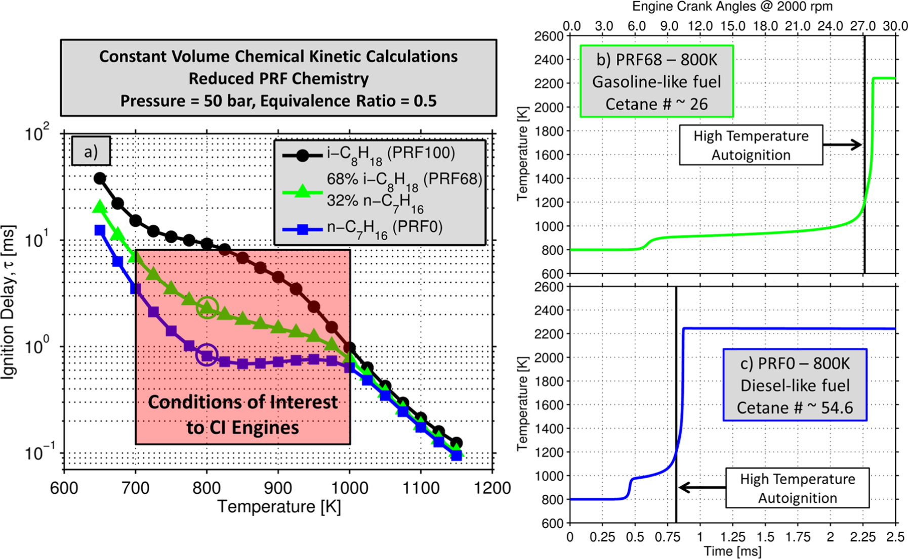
Constant volume chemical kinetic calculations predicting the autoignition delay of primary reference fuel blends (iso-octane and n-heptane). 8 (a) Ignition delay as a function of initial temperature for three fuels. (b) Mixture temperature as a function of time for the PRF68 fuel blend. (c) Mixture temperature as a function of time for the PRF0 fuel blend. Plots (b) and (c) have horizontal axes for engine crank angles at 2000 r/min for reference. Note, cetane number for PRF0 and PRF68 from a correlation by Kalghatgi. 6
Regardless of the fuel properties, PCCI combustion modes have been shown to have challenges associated with limited operable load range, poor combustion efficiency, combustion timing controllability, and high pressure rise rates leading to high combustion noise. In an effort to address these challenges while maintaining low NOx and soot emissions, researchers have been using various levels of in-cylinder fuel stratification (i.e. non-uniform fuel distribution).
The purpose of this article is to review and provide a perspective on the variety of fuel injection strategies that are being investigated for low temperature gasoline compression ignition (LTGCI). The level of fuel stratification in-cylinder at the start of combustion is, in reality, a continuum ranging from fully premixed (homogeneous charge of fuel and air) to heavily stratified heterogeneous operation, such as diesel combustion. However, to gain perspective on the impact of fuel stratification on gasoline compression ignition, the authors have identified three representative operating strategies: PFS, MFS, and HFS. This review article will not include technologies such as spark-assisted compression ignition, variable valve trains, variable compression ratio, enhanced thermal stratification, direct water injection, or dual-fuel compression ignition as means to achieve LTC with gasoline. To highlight the differences between PFS, MFS, and HFS with gasoline, computational fluid dynamics (CFD) modeling of the in-cylinder processes was used. Additionally, comparisons will be made to a CDC strategy.
In this study, a relatively low-octane gasoline fuel will be used for illustration (PRF68). Low-octane gasoline fuels for compression ignition engines are attractive for a variety of reasons. The use of lower octane gasolines directly could require less refinery octane upgrading, which would be less expensive to manufacture and would produce less CO2 emissions during production. 12 From an engine combustion standpoint, the lower octane gasoline fuels have been shown to cover a wider operating range for heavily stratified combustion while yielding lower combustion noise than conventional, higher-octane gasolines. 13 Finally, for more premixed strategies, the ignition delay of low-octane gasolines has been shown to be sensitive to the mixture equivalence ratio, thus allowing fuel stratification to be a potential method in theory to control the timing and rate of heat release. 14
Fuel stratification levels for LTGCI
The LTGCI injection strategies are binned according to their level of in-cylinder fuel stratification at the start of combustion: partial, moderate, and heavy. Many of these strategies utilize multiple injections, and thus, an injection centroid was used as a metric to determine their fuel stratification bin. The injection centroid (θinj) is defined as
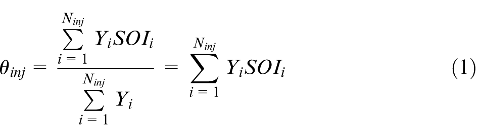
where Ninj is the number of fuel injection events, Yi is the mass fraction of fuel in injection i, and SOIi is the start of injection of injection i. This is essentially the fuel mass weighted average injection timing. This will be used as the metric to quantify the level of fuel stratification in-cylinder at the start of combustion. The guidelines used for binning the different LTGCI operational strategies are shown in Figure 4 along with a simple description of each operational strategy with regard to fuel injection events.
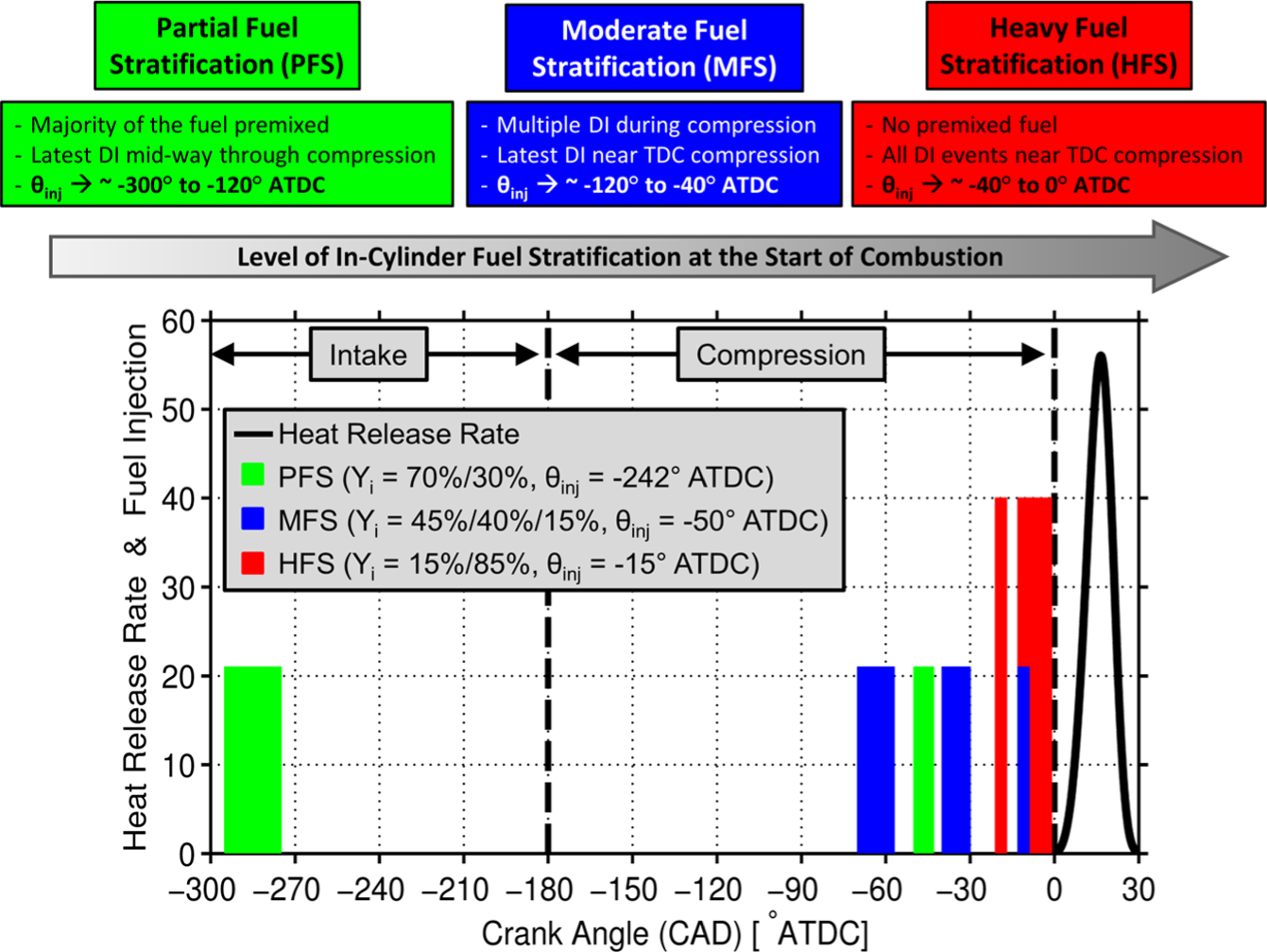
Descriptions and definitions of the three bins of fuel stratification for LTGCI and examples of common fuel injection strategies in relation to the intake stroke, compression stroke, and combustion heat release rate. The fuel injection event bar’s width is proportional to the amount of fuel injected, and its height is proportional to the injection pressure.
Figure 4 also shows examples of common fuel injection strategies to achieve PFS, MFS, and HFS for LTGCI. The injection strategies shown here are somewhat arbitrary but are guided by common themes in the literature. PFS can use port fuel injection or very early direct injection during the intake stroke to create a nearly homogeneous charge of fuel and air. Subsequent direct injections occur during the compression stroke to create slight levels of fuel stratification in an attempt to create sequential autoignition events while maintaining ultra-low NOx and soot emissions.15–28 MFS increases the stratification level by reducing to the amount of premixed fuel and typically features all direct injections during the compression stroke. In addition, MFS strategies typically feature a fuel injection event near top dead center (TDC) of the compression stroke to trigger combustion.29–40 Finally, HFS utilizes the highest level of fuel stratification and typically features no premixed fuel and direct injection(s) relatively close to TDC.41–69 HFS tends to utilize higher fuel injection pressure compared to PFS and MFS in order to get the fuel injection events completed before the autoignition event, as illustrated in Figure 4 by the bar height. However, with gasoline-like fuels, due to their resistance to autoignition and high volatility, the injection pressure requirements for HFS are still significantly lower than those required for diesel PCCI. The subsequent sections of this article will use CFD simulations to illustrate the differences between these LTGCI operating strategies, which cover a broad range of in-cylinder fuel stratification levels.
Multi-dimensional CFD engine modeling
The KIVA3V Release 2 CFD code was used.70–72 The model uses the most popular approach for modeling engine sprays, the Lagrangian-Drop Eulerian-Fluid (LDEF) method, in which liquid fuel is treated as Lagrangian parcels and the ambient gas is discretized into Eulerian cells. Figure 5 shows a high-level illustration of the CFD modeling approach and the physical and chemical processes considered. Several sub-model improvements have been made to the KIVA3V code at the University of Wisconsin-Madison’s Engine Research Center, including fuel droplet breakup, droplet evaporation, droplet collision modeling, turbulence modeling, and semi-detailed chemical kinetics. For the sake of brevity, these sub-model improvements will not be discussed here. For a brief overview of the simulation methodology and sub-model improvements, see Dempsey et al., 73 and Dempsey 74 For a detailed review of the CFD modeling approach, see the lecture series given by Professor Rolf Reitz. 75
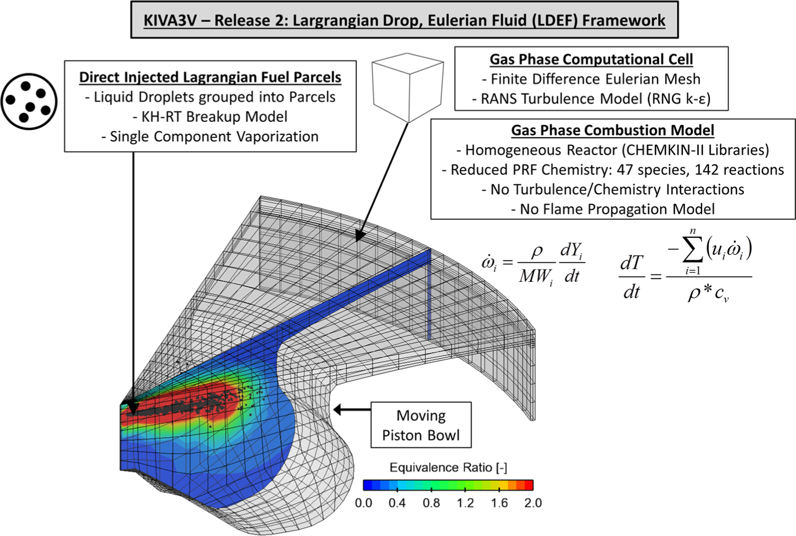
Illustrative overview of the computational fluid dynamics (CFD) modeling approach used in this study for in-cylinder engine processes (e.g. liquid fuel injection, spray breakup, droplet evaporation, turbulent mixing, and combustion).
The closed valve portion of the four-stroke cycle is being simulated, which is intake valve closing (IVC) to exhaust valve opening (EVO). At IVC, the in-cylinder pressure, temperature, and gas composition are assumed to be uniform. Any direct injection events that take place before IVC or port injection events are assumed to be fully premixed in the gas phase with the intake charge. This only applies to the PFS case examined in this study, which has a fuel injection event early in the intake stroke (∼−325° after top dead center (ATDC). In this study, 0° ATDC denotes TDC of the compression stroke. Dempsey et al. 26 have shown that this assumption is probably valid due to the lack of sensitivity to the timing of this early injection, as long as it occurred during the intake stroke (i.e. −360° to −180° ATDC). The in-cylinder velocity profile, magnitude (i.e. swirl and tumble), and turbulence intensity are all initialized at IVC based on experiments.
It is assumed that each spray plume is symmetric about the cylinder axis; thus, only one of the direct injected spray plumes is simulated and there are periodic boundaries on each side of the mesh. The grid had an approximate cell size of 1.7 mm, an azimuthal resolution of 2.8°, and total cell count of ∼10,000. Generally speaking, this is a coarse mesh for spray and combustion simulations. Dempsey et al. 73 showed that coarser meshes such as this one tend to under-predict axial spray penetration and over-predict radial fuel/air mixing. However, Dempsey 74 also showed that despite these discrepancies, the coarse mesh reasonably well captures the heat release rate (HRR) and engine-out emissions of stratified LTC operation with PRF25 fuel in the same engine platform used in this study.
For the LTGCI strategies, the fuel used was PRF68 (68% iso-octane and 32% n-heptane). This represents a gasoline-like fuel in terms of volatility with relatively high fuel reactivity (i.e. lower octane number than market gasoline), akin to a naphtha or straight run gasoline. 57 As shown in Figure 3, this fuel has an estimated cetane number of 26. In the simulations, the physical properties of the liquid fuel were taken to be that of iso-octane (e.g. boiling point, density, viscosity, surface tension). Once evaporated into the gas phase, the chemical kinetics of the PRF68 fuel blend are modeled with a reduced PRF mechanism developed by Ra and Reitz 8 A CDC strategy is also simulated for comparison. For this case, the physical properties of the liquid fuel are taken to be that of tetradecane and the gas phase kinetics are modeled as pure n-heptane (PRF0) using the aforementioned PRF mechanism. 8
With regard to emissions modeling, NOx emissions are predicted using a 4 species, 12 reaction chemical mechanism which includes NO, NO2, and N2O.76,77 A phenomenological two-step soot model is used in the simulations, but soot emissions are not reported. 76 Research has shown that the composition and morphology of soot/particulate matter emissions from LTC strategies can vary widely,78–81 and it has also been shown that the two-step soot model requires significant tuning to achieve predictions over a range of combustion modes. 82 Therefore, in this study, the qualitative sooting tendency of a given combustion strategy will be discussed using local equivalence ratio versus local temperature diagrams, like the one shown in Figure 1.
Engine geometry and operating conditions
The engine geometry used in this study is that of a model year 2007 General Motors (GM) 1.9L diesel engine. The base engine geometry is shown in Table 1.
Geometric specifications of the engine and direct injector used in this study.
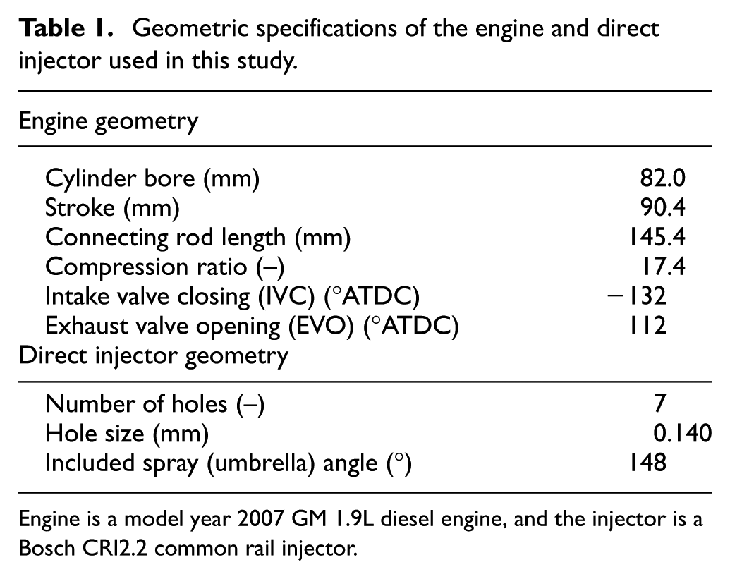
Engine is a model year 2007 GM 1.9L diesel engine, and the injector is a Bosch CRI2.2 common rail injector.
The stock re-entrant piston bowl designed for diesel combustion was used, which is shown in Figure 5. Also, the stock common rail diesel injector was used, with varying injection pressures. The LTGCI combustion strategies investigated here are expected to be sensitive to the combustion chamber shape, compression ratio, and injector configuration. Thus, it is important to realize that these modeling results are not all-encompassing and should not be used to create overly wide generalizations. The goal of this study was to provide a perspective on gasoline compression ignition with respect to fuel stratification.
The simulated operating conditions for CDC, PFS, MFS, and HFS are shown in Table 2. An operating condition of 2000 r/min, ∼6 bar gross indicated mean effective pressure (IMEPg) was chosen to be representative of light-duty driving (i.e. moderate speed/load condition). The gross cycle includes the compression and expansion strokes only (-180 to 180 ATDC). Indicated means the cycle work was calculated from the cylinder pressure, neglecting engine friction. In this study, the predicted closed-cycle piston work (IVC to EVO) from the CFD simulations was combined with experimental data at a matched operating condition to calculate the gross indicated work for each strategy. The air-handling system boundary conditions were taken from multi-cylinder engine experiments of the GM 1.9L engine with the production variable geometry turbocharger and a high-pressure loop EGR system at a match operating condition. 26 As mentioned previously, dilution, along with fuel/air mixing, is one of the keys to LTC. Dilution with EGR is beneficial to reduce combustion temperatures via a reduction of the intake oxygen concentration and an increase in the intake gas’s specific heat. 83 In this study, 30% external EGR was used for all LTGCI strategies. In the CFD simulations, EGR is defined on a molar basis as the ratio of intake CO2 to exhaust CO2, and the recirculate exhaust is comprised only of complete combustion products (CO2, H2O, O2, and N2). This EGR level was chosen based on experiments at a matched speed and load point on the aforementioned multi-cylinder GM 1.9L engine. This is near the maximum amount of EGR that can be driven while maintaining an intake manifold pressure of 1.2 bar at this speed/load condition. This is not to say that other air-handling systems could not achieve higher EGR levels, and that the results shown here are not sensitive to the boundary conditions, but this serves nicely as a production-viable illustration of the strategies and their individual opportunities and challenges.
Base operating conditions for the CFD simulations of PFS, MFS, and HFS LTGCI operation.
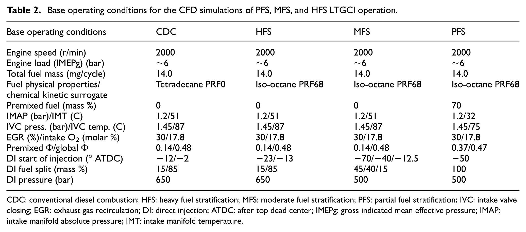
CDC: conventional diesel combustion; HFS: heavy fuel stratification; MFS: moderate fuel stratification; PFS: partial fuel stratification; IVC: intake valve closing; EGR: exhaust gas recirculation; DI: direct injection; ATDC: after top dead center; IMEPg: gross indicated mean effective pressure; IMAP: intake manifold absolute pressure; IMT: intake manifold temperature.
Table 2 shows the equivalence ratio (Φ) for the premixed charge at IVC and the global mixture once all the fuels have been injected for each operating strategy. The conventional definition of equivalence ratio for engine combustion is the stoichiometric air/fuel ratio divided by the actual air/fuel ratio, both for local and global conditions. However, in this analysis, the equivalence ratio was calculated following the work of Babajimopoulos et al. 84 and Mueller 85 in which the equivalence ratio is determined by counting carbon, hydrogen, and oxygen atoms in a given gas mixture. In this way, the equivalence ratio is essentially a conserved scalar. For an unreacted mixture of fuel and air, the equivalence ratio definitions are equivalent. However, with the conventional definition, once the fuel is reacted the equivalence ratio parameter becomes less useful. By following the work of Babajimopoulos et al. 84 and Mueller, 85 the equivalence ratio for a given mixture is constant, whether it is unreacted fuel and air, partially reacted, or complete combustion products. Thus, for the cases without premixed fuel, MFS and HFS, there is a non-zero premixed equivalence ratio due to the EGR of 0.14. This is essentially stating that the intake gas composition is equivalent to that of the exhaust composition of an engine running at a global equivalence ratio of 0.14. This method of calculating the equivalence will be used for global mixtures and individual CFD cells throughout this study.
Finally, Table 2 shows the fuel injection strategies for each combustion mode. Note that all the combustion strategies have essentially the same combustion phasing, denoted as CA50 (CA50 is defined as the crank angle at which 50% of the accumulated cycle heat release due to combustion has been met.), which is 5°–6° ATDC. The CDC injection strategy is modeled after that of the model year 2007 GM 1.9L diesel engine in terms of its pilot dwell, pilot duration, and injection pressure. In this study, the injection velocity profiles are simplified and taken to be that of a trapezoid with the peak injection velocity calculated using Bernoulli’s equation and the injection pressure. The injection timing for CDC operation was adjusted to achieve the desired CA50. HFS uses two direct injections close to TDC, somewhat akin to the CDC strategy except that the injections are advanced in this case due to the lower reactivity of the fuel. MFS has no premixed fuel and three direct injections all during the latter half of the compression stroke and used a lower injection pressure of 500 bar. PFS premixes 70% of the total fuel at IVC. The remainder of the fuel is direct injected at −50° ATDC with an injection pressure of 500 bar. PFS operation used a lower intake temperature to maintain the targeted combustion phasing.
Simulated results of the baseline operating condition
This section reviews the simulation results and analyzes in-cylinder processes for each combustion strategy at the baseline operating conditions. Figure 6 shows the predicted in-cylinder pressure, HRR due to combustion, and the input fuel injection velocities. CDC operation is the only strategy that has positive overlap between injection events and combustion, which will be shown in a later section to be detrimental for soot formation. HFS features near TDC injection events but has approximately an 8° crank angle dwell between the end of injection and the start of combustion. MFS has a near TDC injection but only contains 15% of the total fuel.
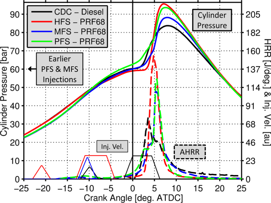
Simulated in-cylinder pressure, heat release rate (HRR), and fuel injection velocity for each individual combustion strategy. Note that the injection event for PFS is earlier at −50° ATDC and MFS also has two earlier injections that are not shown at −70° ATDC and −40° ATDC.
A summary of the predicted engine performance and emissions for the various strategies is shown in Table 3. Moving to the right across the columns of Table 3, the level fuel stratification at the start of combustion decreases (i.e. more homogeneous combustion). All the combustion strategies yield a high gross indicated efficiency (GIE) of ∼46%. Due to its high combustion efficiency, CDC operation yields, by a slight margin, the highest GIE. The LTGCI strategies have lower combustion efficiency, particularly MFS and PFS, which is expected, especially at this light-to-moderate engine load due to the low combustion temperatures associated with very lean mixtures. However, due to reduced heat transfer losses and more favorable thermodynamic properties of the working fluid, both stemming from the low combustion temperatures, the GIE remains high for these strategies.
Simulation results at the baseline operating condition for CDC, PFS, MFS, and HFS.
CDC: conventional diesel combustion; HFS: heavy fuel stratification; MFS: moderate fuel stratification; PFS: partial fuel stratification; ATDC: after top dead center; UHC: unburned hydrocarbon; PPRR: peak pressure rise rate; CNL: combustion noise level; CFD: computational fluid dynamics; IMEPg: gross indicated mean effective pressure; ISFCg: gross indicated specific fuel consumption.
All parameters that are based on cycle work or cycle power are taken as the gross indicated cycle (−180°–180° ATDC). The closed-cycle CFD simulations were combined with experimental data at a matched condition to construct the gross cycle.
The NOx emissions are strongly tied to the level of fuel stratification, with the NOx emissions decreasing as the combustion process becomes more homogeneous. Interestingly, NOx emission from HFS is equal to that of CDC operation despite having a rather different injection schedule. As mentioned previously, the soot emissions predictions will not be shown, but instead a qualitative sooting tendency will be discussed.
Finally, the peak pressure rise rates (PPRRs) predicted by the CFD simulations are shown in Table 3. This parameter is of interest because it has been shown to be the primary driver in combustion-generated noise in engines.86,87 In addition, the combustion noise level (CNL) is shown, which was calculated using the algorithm put forward by Shahlari et al. 88 Considering these are closed-cycle simulation results, an algorithm also put forward by Shahlari et al. 89 was used to calculate the full four-stroke cycle noise from closed-cycle simulation results. As shown in Table 3, CDC operation yields the lowest combustion noise, which is expected due to the mixing limited nature of the majority of the combustion process, which yields a more sedate energy release than volumetric autoignition. It is interesting however that there is a non-monotonic trend in combustion noise with respect to fuel stratification, with MFS operation being quieter than both PFS and HFS.
CDC
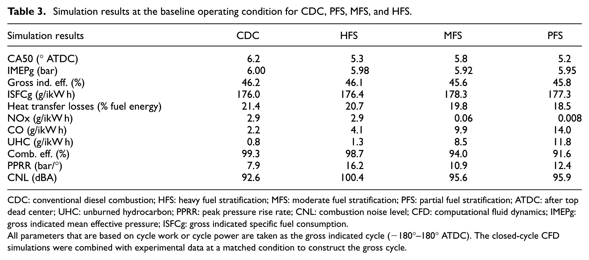
Figure 7 shows the simulation predictions of the in-cylinder mixture distribution for CDC operation at 6.5° ATDC, which is just after CA50. Figure 7(a) shows the predicted cylinder pressure, HRR, and input injection velocity as a function of crank angle. Figure 7(b) shows the local equivalence ratio versus local temperature plot and the regions of high NOx and soot formation. Figure 7(c) and (d) shows in-cylinder images colored by equivalence ratio and temperature, respectively. The CDC operation results in a mixing limited combustion event that is mainly contained in the piston bowl, which yields a wide range of conditions. In the center of the diffusion flame are regions of high equivalence ratio (Φ > 2.0) and high temperature (T > 1500 K) forming a relatively large amount of soot. At the periphery of the diffusion flame are stoichiometric mixtures (Φ = 1.0) at even higher temperatures (T = 2600 K) which produce high NOx formation rates. These mixture conditions that yield high NOx and soot emissions are the thrust of what LTC operation aims to avoid by creating a more premixed and dilute combustion event.
CFD simulation results for the conventional diesel combustion (CDC) strategy at 6.5° ATDC. (a) Cylinder pressure, heat release rate, and injection velocity versus crank angle. (b) In-cylinder mixture conditions (local equivalence ratio vs local temperature). Each datum is an individual CFD cell. (c) In-cylinder image of local equivalence ratio. (d) In-cylinder image of local temperature. Cut planes are coincident with the injection axis.
HFS
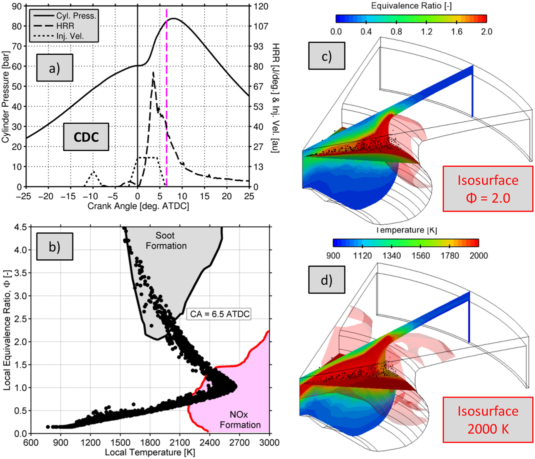
Figure 8 shows the simulation predictions for HFS operation with PRF68 fuel at 5.5° ATDC. HFS operation has sufficient separation between the fuel injection event and the start of combustion that the soot formation island is avoided entirely. Thus, this strategy at this operating condition is expected to yield near zero soot emissions. However, a significant portion of the in-cylinder mixture resides in the equivalence ratio range of ∼0.6 to ∼1.4 during the combustion event, resulting in high NOx formation rates, at least at this modest EGR level of 30%. It is clear that for HFS strategies, higher levels of EGR are required for LTC operation, at least in terms of ultra-low NOx emissions. This has been shown by Manente et al. 50 for a variety of gasoline-like fuels. They have shown that for HFS-like injection strategies with gasoline, a nearly constant EGR level of 50% is required for NOx emissions below 0.2 g/ikW h, which is still significantly less than required for simultaneous low NOx and soot emissions with diesel fuel. 4
CFD simulation results for the heavy fuel stratification (HFS) strategy with PRF68 fuel at 5.5° ATDC. (a) Cylinder pressure, heat release rate, and injection velocity versus crank angle. (b) In-cylinder mixture conditions (local equivalence ratio vs local temperature). Each datum is an individual CFD cell. (c) In-cylinder image of local equivalence ratio. (d) In-cylinder image of local temperature. Cut planes are coincident with the injection axis.
Another noteworthy characteristic of this HFS condition is the high PPRR (16.2 bar/°) resulting in a high CNL of 100.4 dBA, even higher than the more premixed strategies like MFS and PFS, which is somewhat counterintuitive. This is a challenge, particularly in the light-duty marketplace where combustion noise is an important metric. 90 The reason for the high pressure rise rate stems from the very high HRR and short combustion duration. Essentially, the in-cylinder fuel distribution at the start of combustion does not yield a wide range of autoignition times, which is needed to elongate the heat release for kinetically controlled combustion such as this. For this HFS operating strategy, the short combustion duration stems from a competition between the increased reactivity of the higher equivalence ratio regions and evaporative cooling in these regions. This can be better understood by looking at the in-cylinder fuel distribution.
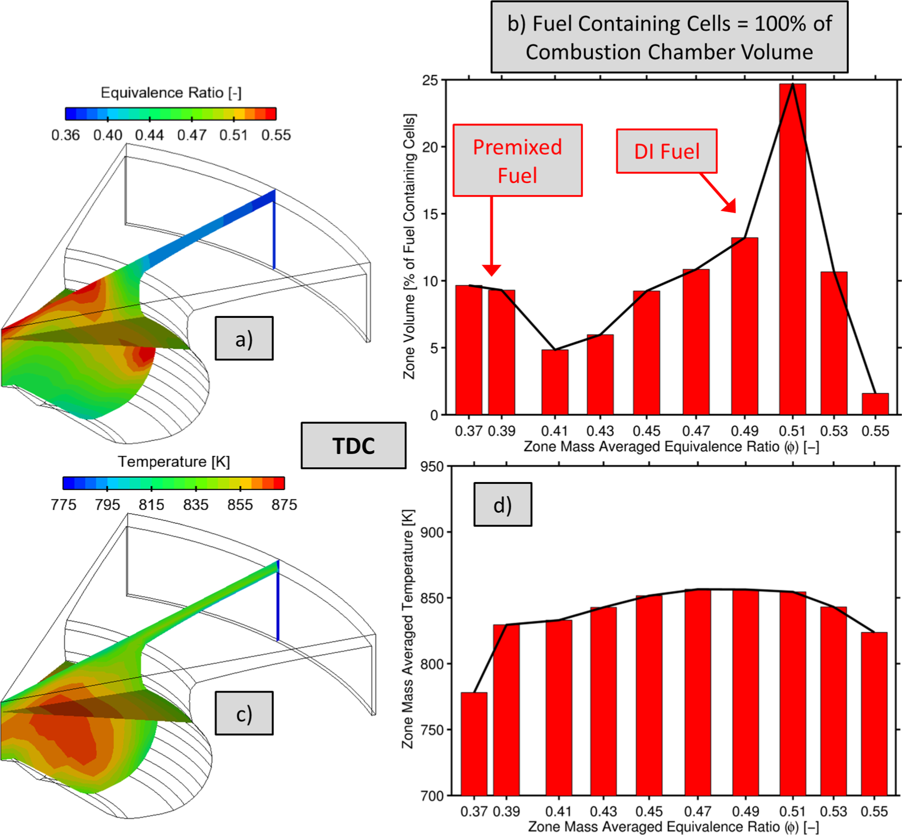
Figure 9 shows the in-cylinder fuel and temperature distributions for HFS operation at TDC from a non-reacting CFD simulation. Thus, chemical reactions were not taking place and these distributions are strictly the result of the fuel injection process (e.g. liquid injection, breakup, turbulent fuel/air mixing, and evaporative cooling). The predicted mixture distributions were binned into 10 zones by equivalence ratio. The bin boundaries were linearly spaced between the minimum and maximum equivalence ratio at TDC. The horizontal axis in Figure 9(b) and (d) are the mass averaged equivalence ratio of the all the cells in a given zone and thus are not necessarily evenly spaced. As shown, the regions of higher equivalence ratio, which ignite first for this operating condition, are also the coldest of the fuel containing portions of the combustion chamber. This competes with the increased reactivity of higher equivalence. Throughout the entire chamber, there is a trade-off between equivalence ratio and mixture temperature, which results in a nearly constant ignition delay distribution and ultimately a high rate of energy release. Finally, for reference, the PFS and MFS equivalence ratio ranges are shown in Figure 9(b) as well, which will be discussed next.
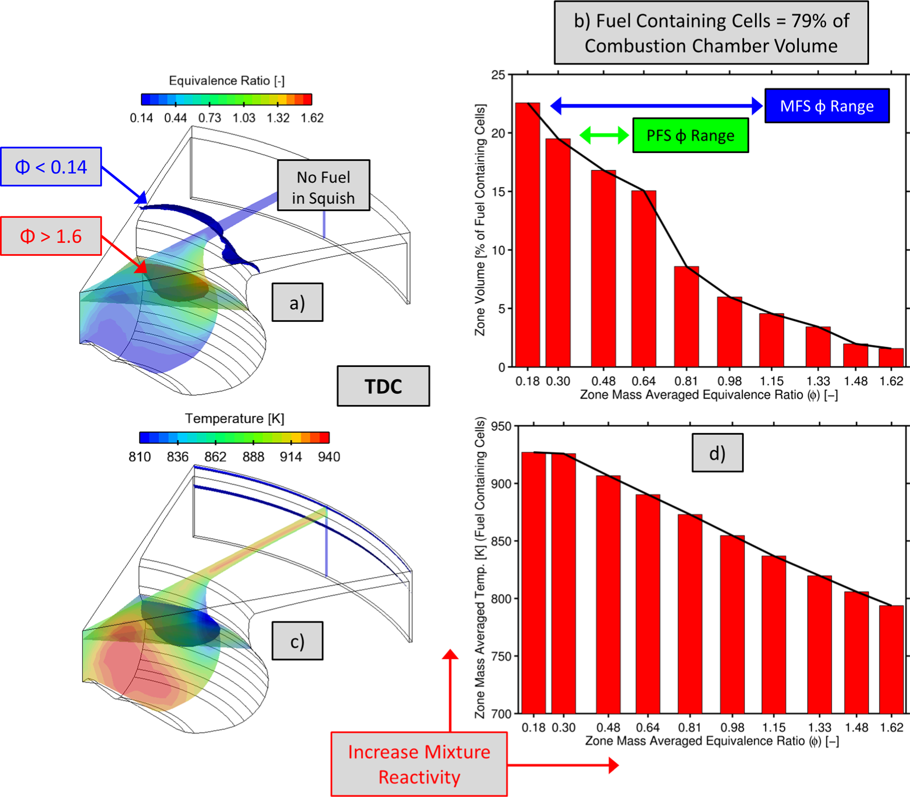
Predicted in-cylinder fuel and temperature distributions at TDC for HFS operation from a non-reacting CFD simulation (i.e. no chemical heat release). (a) Equivalence ratio distribution showing that fuel is contained in the piston bowl and there is no fuel in the squish region. (b) Zonal volume as a function of equivalence ratio for fuel containing portions of the combustion chamber. (c) Temperature distribution. (d) Zonal temperature as a function of equivalence ratio for fuel containing portions of the combustion chamber.
MFS
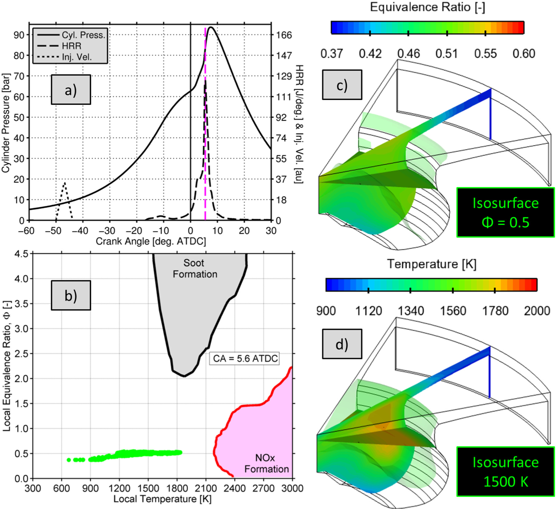
Figure 10 shows the simulation predictions for MFS operation with PRF68 fuel at 5.0° ATDC. The operational strategy results in a more homogeneous mixture during combustion compared to HFS operation. As shown in the figure, the third injection event creates near stoichiometric mixtures (Φ = 1) in the upper portion of the piston bowl and back near the injector nozzle. These regions ignite (i.e. T > ∼1500 K) first, and then there is a cascade of autoignition events down to the regions of lower equivalence ratio. The near stoichiometric regions are forming some NOx emissions, with temperatures in excess of 2400 K, but, as shown in Table 3, the engine-out NOx levels are still ultra-low at 0.06 g/ikW h. It is also clearly shown in Figure 10 that the soot emissions are expected to be ultra-low and near zero for this MFS operating condition due to the fact the soot formation island is avoided entirely.
CFD simulation results for the moderate fuel stratification (MFS) strategy with PRF68 fuel at 5.0° ATDC. (a) Cylinder pressure, heat release rate, and injection velocity versus crank angle. (b) In-cylinder mixture conditions (local equivalence ratio vs local temperature). Each datum is an individual CFD cell. (c) In-cylinder image of local equivalence ratio. (d) In-cylinder image of local temperature. Cut planes are coincident with the injection axis.
Figure 11 shows the fuel and temperature distributions for MFS operation at TDC from a non-reacting CFD simulation. As shown, the charge is significantly more premixed than HFS operation, and the ignition source zones created by the third injection have equivalence ratios of 0.8 and higher but only occupy ∼2% of the combustion chamber. These zones serve as an initiator for combustion without dramatically increasing the NOx emissions due to the fact that they occupy such a small percentage of the in-cylinder charge. The vast majority of the charge is in the equivalence ratio range of 0.4–0.6, which are the zones that autoignite next, right after the ignition source zones. This overall fuel distribution results in good combustion efficiency but still a relatively high peak HRR of just over 100 J/°.
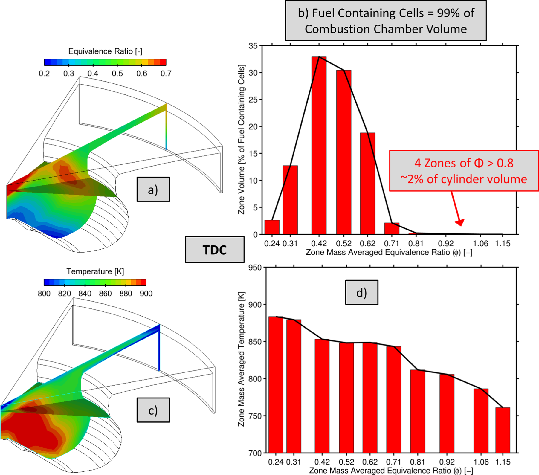
Predicted in-cylinder fuel and temperature distribution at TDC for MFS operation from a non-reacting CFD simulation (i.e. no chemical heat release). (a) Equivalence ratio distribution. (b) Zonal volume as a function of equivalence ratio for fuel containing portions of the combustion chamber. (c) Temperature distribution. (d) Zonal temperature as a function of equivalence ratio for fuel containing portions of the combustion chamber.
PFS
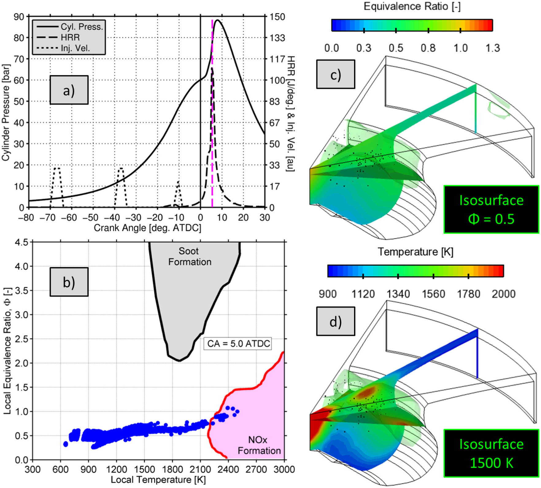
Figure 12 shows the simulation predictions for PFS operation with PRF68 fuel at 5.6° ATDC. This operational strategy results in the most homogeneous mixture considered in this study. The sole direct injection event penetrates into the squish region slightly, but due to the low injection pressure and strong squish flows, the fuel does not penetrate to the liner and the majority of the direct injected fuel resides near the piston bowl rim. Combustion initiates in this location, as shown in Figure 12(d), where the equivalence ratios are the highest. However, the peak equivalence ratios are lean enough such that the NOx emissions are ultra-low, with peak combustion temperatures of only ∼1850 K. Again, the soot emissions are expected to be essentially zero, as illustrated qualitatively in Figure 12(b).
CFD simulation results for the partial fuel stratification (PFS) strategy with PRF68 fuel at 5.6° ATDC. (a) Cylinder pressure, heat release rate, and injection velocity versus crank angle. (b) In-cylinder mixture conditions (local equivalence ratio vs local temperature). Each datum is an individual CFD cell. (c) In-cylinder image of local equivalence ratio. (d) In-cylinder image of local temperature. Cut planes are coincident with the injection axis.
Figure 13 shows the fuel and temperature distributions for PFS operation at TDC from a non-reacting CFD simulation. With 70% of the total fuel premixed at IVC, the equivalence ratio range at TDC is relatively narrow (0.37 < Φ < 0.6). As shown in Figure 13, the equivalence ratio distribution is somewhat bimodal. Approximately 20% of the combustion chamber resides near the premixed equivalence ratio (Φ < 0.4). The remaining 80% of the chamber contains fuel from the direct injection event, which had a start of injection timing of −50° ATDC. As mentioned previously, the direct injected fuel is mainly confined to the piston bowl region with a peak equivalence ratio of ∼0.6 up against the bowl wall and near the piston bowl rim. As shown in Figure 12, and as expected, these regions serve as the ignition source for PFS operation, resulting in a cascade of autoignition events, which is the goal of fuel stratification for LTGCI operation in an attempt to elongate the burn duration and reduce the pressure rise rate. The PFS operating condition studied here yields the lowest NOx emissions and, in a qualitative sense, no soot emissions. However, due to the low combustion temperatures and premixed fuel residing in crevices, the combustion efficiency is rather low at 91.6%. It is expected that the combustion efficiency would improve with a redesigned piston featuring less surface area. The incomplete combustion products from PFS operation are stemming from the squish region of the diesel piston bowl, which has a rather high surface-area-to-volume ratio, leading to high heat transfer losses and incomplete combustion.
Predicted in-cylinder fuel and temperature distribution at TDC for PFS operation from a non-reacting CFD simulation (i.e. no chemical heat release). (a) Equivalence ratio distribution. (b) Zonal volume as a function of equivalence ratio for fuel containing portions of the combustion chamber. (c) Temperature distribution. (d) Zonal temperature as a function of equivalence ratio for fuel containing portions of the combustion chamber.
Summary and discussion
This section will briefly review the opportunities and challenges associated with these LTGCI concepts and discuss needed future research. It is important to remember that this article focused on a relatively high reactivity gasoline (i.e. low-octane number of 68). These LTGCI strategies are expected to be sensitive to fuel reactivity. Thus, fuel effects are an overarching future research need for LTGCI operation. In addition, LTGCI research is currently being conducted primarily on diesel engines. Thus, piston, injector, and in-cylinder flow field research is another overarching future research need. It is probable that a compression ignition engine using gasoline will ultimately use multiple combustion modes to take advantage of the benefits that each level of fuel stratification presents while minimizing the drawbacks.
HFS—opportunities and challenges
HFS operation with gasoline is in reality similar to diesel PCCI operation but with the advantage of using a fuel that has a higher resistance to autoignition than diesel fuel. Thus, the injection events can be advanced slightly and longer time for fuel/air mixing is achieved prior to combustion without requiring a reduced compression ratio or other measuring to lengthen the ignition delay. Low soot emissions can be achieved without massive EGR requirements like diesel PCCI. 4 The combustion efficiency remains high, similar to diesel combustion due to the majority of the fuel burning at near stoichiometric conditions. Finally, a major advantage of HFS operation is that the timing of combustion is determined by the injection timing; thus, HFS is an injection-driven combustion mode, much like CDC or diesel PCCI. Hence, the combustion phasing is readily controlled on a cycle-by-cycle basis through the fuel system, which can be a challenge for LTC.
There are challenges associated with the HFS strategy. Low NOx emissions require relatively high EGR rates due to the high local combustion temperatures. It has been shown by Manente et al. 13 and Solaka et al. 53 that ∼50% EGR and a global equivalence ratio of 0.5–0.7 is required for ultra-low engine-out NOx. It is noteworthy that for the diesel PCCI, the EGR requirements for simultaneously low NOx and soot are higher, upward of 70%, which is needed to suppress soot formation at high equivalence ratios. The challenge is that research has shown that state-of-the-art engine air-handling systems struggle to supply 50% EGR and overall lean equivalence ratios, particularly at higher engine loads. 91 Another challenge that was highlighted in this article is the high energy release rate leading to high pressure rise rates and combustion noise. It was shown that a large portion of the in-cylinder charge is near stoichiometric conditions, which are very energy dense mixtures, resulting in a violent energy release.
Future research directions for HFS operation with gasoline-like fuels will likely take two different paths. One should focus on maximizing engine efficiency and using lean NOx aftertreatment devices to reduce tailpipe NOx levels. It was shown in this work that there is a clear soot emissions benefit with gasoline compared to diesel fuel; this has the potential to improve fuel efficiency by reducing the regeneration needs of a particulate filter. The second path should focus on the areas of engine air-handling systems, combustion chamber design, and injector design. Advanced, high-efficiency air-handling systems will be required to reduce the NOx emissions to ultra-low engine-out levels. As discussed, in the analysis section, the geometric properties of the combustion chamber and the injector play a major role in determining the fuel distribution and subsequent cascade of autoignition events. Research efforts should be put into optimizing the combustion chamber shape and injector geometry to yield a fuel distribution that reduces the combustion noise for HFS operation. Thus, future engines could to take advantage of the high degree of combustion timing controllability, high combustion efficiency, and low soot emissions associated with the HFS LTGCI concept.
MFS—opportunities and challenges
MFS operation, as the title suggests, tends to yield results in between heavy and PFS, particularly in terms of combustion efficiency, heat transfer losses, and NOx emissions. One parameter that does not appear to change monotonically with fuel stratification is the pressure rise rate and combustion noise. The CFD results shown in this work illustrate that MFS yields the lowest pressure rise rate. Sellnau et al. 30 and Tanov et al. 38 have shown experimentally that MFS injection strategies result in longer combustion duration and lower pressure rise rate compared to HFS injection strategies, thus validating the current CFD illustration. This is a major advantage for MFS operation. Another advantage for the MFS strategy is that there is a mechanism by which to control the timing of combustion via the fuel injection strategy with the last near TDC injection. Therefore, MFS is also somewhat of an injection-driven concept, which is important from a controls perspective.
The challenges with MFS operation are the modest combustion efficiency, combustion noise, and NOx and soot emissions associated with the near TDC injection as conditions change. The combustion efficiency appears to be improved compared to fully premixed compression ignition but still relatively low compared to conventional combustion. The MFS strategy did yield the lowest combustion noise of all the LTGCI strategies, but the noise is still relatively high compared to CDC and remains a challenge. Finally, as conditions change, and in turn the amount and timing of the last injection change, NOx and soot emissions have the potential to become problematic.
The recommended future research directions for MFS operation mimic those of HFS operation but for slightly different reasons. The key is to optimize the in-cylinder fuel distribution to maximize the combustion efficiency and elongate the burn duration all while maintaining low NOx and soot emissions. The combustion chamber shape and injector geometry will most certainly need to be optimized for gasoline-like fuels. Additionally, one of the major keys to LTC with any fuel is dilution; thus, improving the efficiency of engine air-handling systems is always a need.
PFS—opportunities and challenges
PFS operation tends to display the same opportunities and challenges as HCCI because they are both kinetically controlled, which are ultra-low NOx and soot emissions with reduced combustion efficiency, higher combustion noise due to rapid combustion, limited operable load range, and little combustion timing control via the fuel injection strategy. In fact, Dec et al. 18 and Dempsey et al. 19 have shown that at lower operating pressures, PFS and HCCI operation are actually very similar due to the fact the fuel’s autoignition process is not very sensitive to the mixture equivalence and the competition between charge cooling and increased equivalence ratio. However, Dec et al. 18 have also shown that as the operating pressure increases, the sensitivity to the equivalence ratio increases, thus making PFS injection strategies effective at reducing the combustion-generated noise by elongating the heat release. Therefore, efficient and high boost capable air-handling systems are required to reach high operating pressures.
One future research direction for PFS operation should focus on fuel properties. For successful PFS operation, the fuel’s autoignition process must be very sensitive to changes in equivalence ratio, and in addition, high latent heat of vaporization tends to counter these affects. Yang et al. 14 have shown that fuels that display low- and intermediate-temperature heat release tend to be good candidates for PFS. PFS operation is most suited for the mid-load range of the engine. At low load, combustion efficiency is very low due to the low combustion temperatures associated with the very lean charge. At higher loads, the peak cylinder pressure and pressure rise rates are typically too high.
General trends and observations
Figure 14 provides an illustrative overview of the goals of LTGCI relative to homogeneous and heterogeneous combustion. This study utilized CFD modeling of the in-cylinder processes to illustrate the differences between the various levels of fuel stratification, and comparisons were made with CDC. It is expected that these operating strategies will be sensitive to the combustion chamber and injector design; thus, it is important to realize that these modeling results are not all-encompassing and should not be used to create overly wide generalizations. However, the modeling results can be used to highlight some overarching opportunities and challenges with the different stratification bins, realizing that there is in fact a continuum between all of the defined bins.
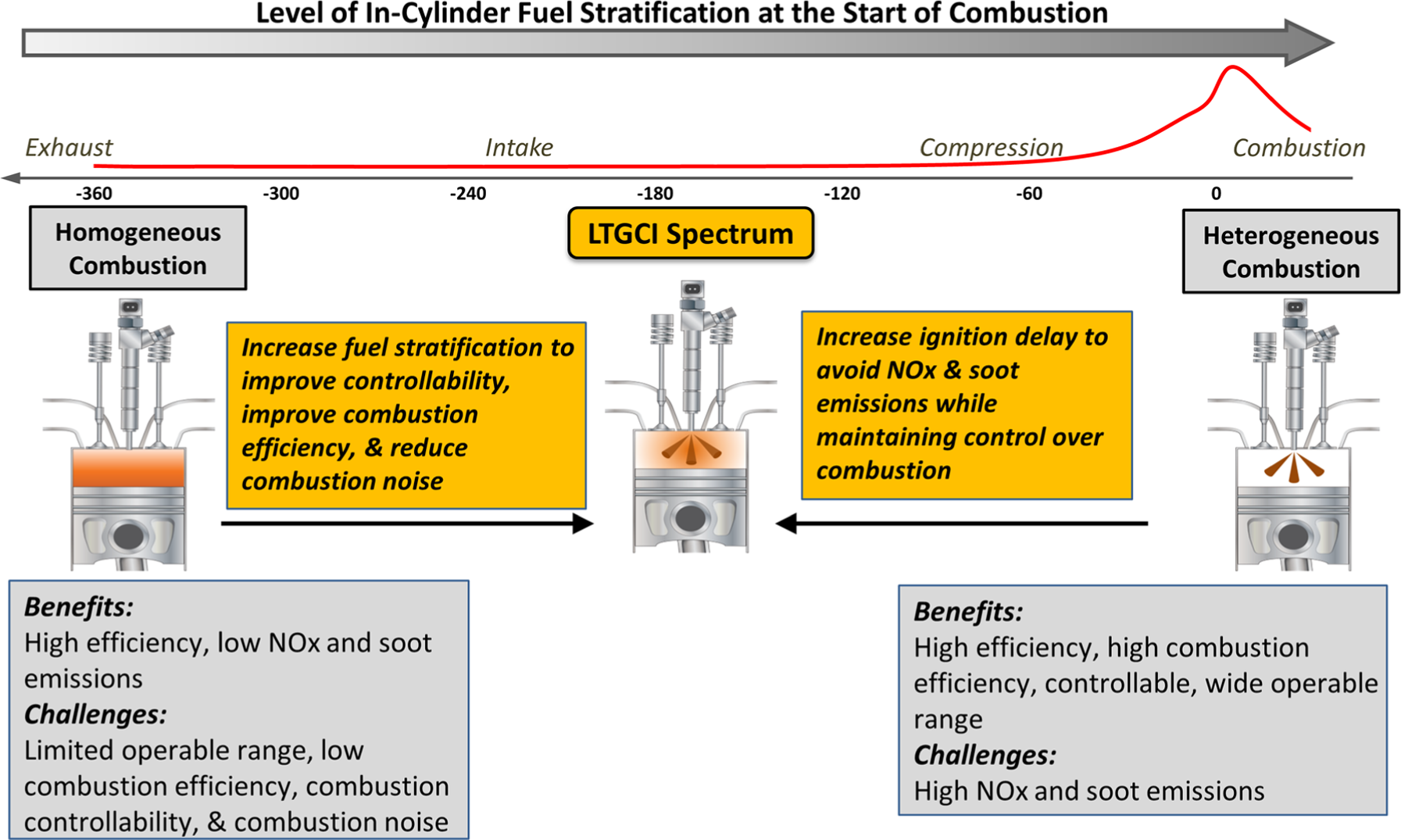
Range of in-cylinder fuel stratification for compression ignition engines. Focus of this article was to review and provide a perspective on the range fuel injection strategies for LTGCI operation (i.e. partial, moderate, and heavy fuel stratification).
All of the operating strategies yielded high GIE (∼46%) due to the high compression ratio and globally lean air/fuel ratio. It was shown that there is a trade-off between fuel stratification and combustion efficiency, with the more stratified conditions yielding higher combustion efficiency. The lower combustion efficiencies observed for the more premixed concepts stem from overly lean regions which result in overly low combustion temperatures (i.e. less than ∼1400 K). Despite the lower combustion efficiency, the more premixed strategies, such as MFS and PFS, still yielded high indicated efficiency due to reduced heat transfer losses and more favorable thermodynamic properties of the working fluid, both stemming from the lower combustion temperatures. As expected, the more stratified cases yielded higher NOx emissions than the more premixed operating strategies due to locally high combustion temperatures. All of the LTGCI strategies investigated appear to form very little soot due to the fact that all injection events have ceased prior to the start of combustion. Finally, combustion noise displayed a non-monotonic trend with fuel stratification. This is an important finding that must be exploited to minimize engine noise while achieving high-efficiency LTC. Each mode of LTGCI operation has unique opportunities and challenges that can be exploited in different regions of the engine operating map.
Footnotes
Acknowledgements
The authors would like to gratefully acknowledge the support and guidance of this work provided by the US Department of Energy's Vehicle Technologies Office under the Fuel and Lubricant Technologies subprogram managed by Kevin Stork.
Declaration of conflicting interests
The author(s) declared no potential conflicts of interest with respect to the research, authorship, and/or publication of this article.
Funding
The author(s) disclosed receipt of the following financial support for the research, authorship, and/or publication of this article: Oak Ridge National Laboratory (10.13039/100006228 DE-AC05-00OR22725).