
Abstract
Mechanical model is generally required in high dynamic sensorless motor control schemes for zero phase lag estimation of rotor position and speed. However, the rotational inertia uncertainty will cause dynamic estimation errors, eventually resulting in performance deterioration of the sensorless control system. Therefore, this article proposes a high dynamic performance sensorless control strategy with online adjustment of the rotational inertia. Based on a synthetic back electromotive force model, the voltage equation of interior permanent magnet synchronous motor is transformed to that of an equivalent non-salient permanent magnet synchronous motor. Then, an extended nonlinear observer is designed for interior permanent magnet synchronous motor in the stator-fixed coordinate frame, with rotor position, speed and load torque simultaneously estimated. The effect of inaccurate rotational inertia on the estimation of rotor position and speed is investigated, and a novel rotational inertia adjustment approach that employs the gradient descent algorithm is proposed to suppress the dynamic estimation errors. The effectiveness of the proposed control strategy is demonstrated by experimental tests.
Introduction
Due to its high torque density, high efficiency and wide constant-power operating range, interior permanent magnet synchronous motor (IPMSM) has been widely used for industrial applications and vehicle propulsions.1–4 In high-performance field-oriented control systems of IPMSM, rotor position information is generally required for the coordinate transformation and speed feed-back control. Mechanical position sensors are commonly employed to measure the rotor position, such as resolvers and encoders, which are vulnerable to strong vibration, high operating temperature and humid atmosphere. To enhance the system robustness and reduce the manufacture and maintenance cost, various sensorless control schemes have been proposed to eliminate the need for mechanical position sensors.5–17
The model-based sensorless methods are widely used in medium to high speed range for their simplicity and high efficiency, which mainly include the back electromotive force (EMF) estimation–based method,5,6 sliding-mode observer (SMO),7–9 extended Kalman filter (EKF),10,11 model reference adaptive system (MRAS)12,13 and nonlinear observer.14–17 Among them, the nonlinear observer proposed by Zhu et al. 14 and Solsona et al. 15 is a promising candidate for high dynamic sensorless control, which estimates rotor position, speed and load torque simultaneously. According to Bhangu and Bingham, 16 genetic algorithms, employing the principles of evolution, natural selection and genetic mutation, are introduced for the selection of nonlinear observer gains. Mao et al. 17 used an equivalent flux error to represent the electrical parameter inaccuracies, and steady-state estimation errors can be eliminated by compensating for the equivalent flux error in the nonlinear observer. However, dynamic estimation errors will arise during the acceleration and deceleration periods if inaccurate system rotational inertia is adopted.
The obstacle in extending the nonlinear observer to IPMSM lies in the position-dependent inductance matrix owing to the rotor saliency. A nonlinear observer for IPMSM is built by Bisheimer et al. 18 by directly calculating the position-dependent inductance matrix and is rather complicated. The extended electromotive force (EEMF) model proposed by Chen et al. 19 is capable of transforming the IPMSM into an equivalent non-salient permanent magnet synchronous motor (PMSM), but the cross-coupling introduced between the two orthogonal axes in the stator-fixed coordinate frame is inconvenient for observer construction. A group of more concise models is proposed essentially based on the flux-linkage model of d-axis,8,9,20 but the variation of d-axis flux-linkage needs to be further considered for back-EMF-based sensorless methods.
In this article, the voltage equation of IPMSM is reconstructed based on a synthetic back-EMF, which is equivalent to that of a non-salient PMSM. Then, an extended nonlinear observer is designed for IPMSM in the stator-fixed coordinate frame, with rotor position, speed and load torque simultaneously estimated. The effect of inaccurate rotational inertia on the dynamic performance of rotor position and speed estimation is investigated, and explicit estimation errors are derived. Considering the sensitivity to mechanical parameter uncertainty, a novel online rotational inertia adjustment strategy for sensorless control system is proposed, employing the gradient descent algorithm, which is very simple and advantageous for industrial applications. The rest of this article is organized as follows. In section ‘Sensorless control of IPMSM based on extended nonlinear observer’, an extended nonlinear observer is designed for IPMSM based on the synthetic back-EMF model. In section ‘Rotational inertia adjustment strategy’, explicit estimation errors of the speed and position are derived, and an online inertia adjustment strategy is proposed to suppress the dynamic estimation errors. Experimental setup and evaluation of the proposed strategy are given in section ‘Experiments and analysis’.
Sensorless control of IPMSM based on extended nonlinear observer
Non-salient model for IPMSM
The voltage equation of IPMSM in the

where

It can be observed from equation (1) that there is a

where
In a typical vector control system, the stator currents in the

where
By substituting

The phasor diagram of IPMSM is depicted in Figure 1. It can be seen that

Phasor diagram of IPMSM.
Here, a synthetic back-EMF,

The synthetic back-EMF can be interpreted as the equivalent back-EMF of IPMSM. Since the slope of the d-axis current is limited and the difference of

Substituting equations (4)–(6) into equation (1) and considering that
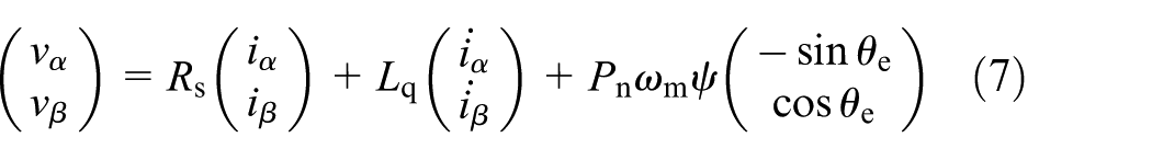
where
It should be noted that the rotor position–dependent inductance matrix disappeared at the expense of introducing
where
Extended nonlinear observer for IPMSM
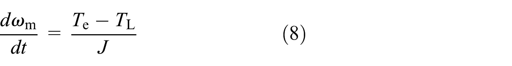
By incorporating the electrical equation (7) and mechanical equation (8), the dynamic model of IPMSM can be established as

Note that compared with the system sampling frequency, the load torque can be assumed to be constant during a very short time, that is,
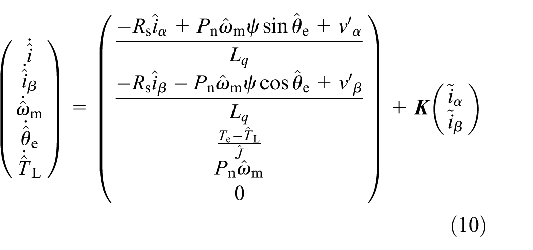
where variables with ‘^’ denote the estimated values, variables with ‘~’ denote the estimation errors,

For asymptotic convergence of the extended nonlinear observer, the state linearization method shown in equation (11), which is identical to that applied to surface permanent magnet synchronous motor (SPMSM), is utilized to determine the structure of the observer gain matrix14,15

By letting
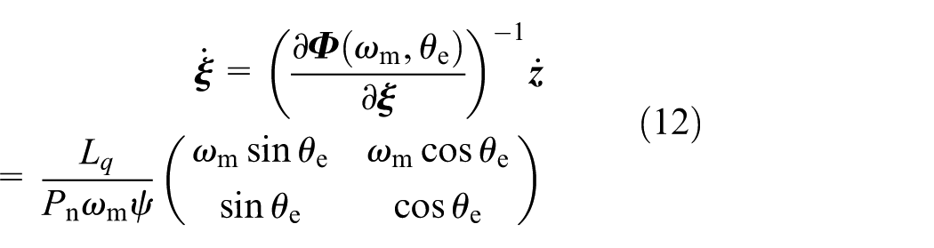
By transforming the PMSM model and the extended nonlinear observer to the polar coordinate frame with the nonlinear coordinate transformation given in equation (11), linearized observer gain matrix can be determined employing the linear control theory. Then, the rotor position and speed can be obtained from the polar coordinate frame as

The ambiguous in the sign of
where
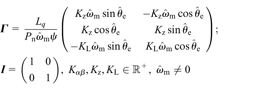
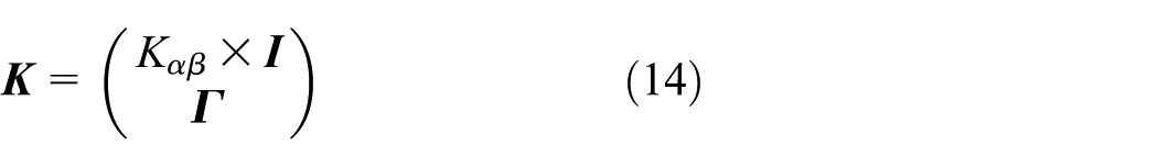
Observer gain selection
Assuming the model parameters are accurate, transfer functions of the current estimation error can be obtained by subtracting equation (10) from (9) and transforming to s-domain
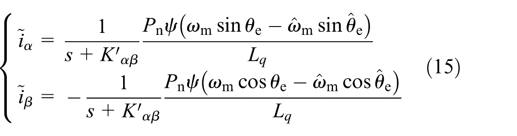
where
The linearized transfer functions of the mechanical model regulator around the equilibrium point are
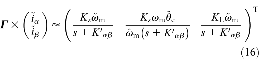
where
Based on equations (10) and (16), the rotor speed and position estimators can be represented by two closed-loop tracking control systems, as shown in Figure 2. And the real speed and position can be interpreted as virtual input of the speed and position estimators.

Block diagram of the linearized speed and position estimators of the extended nonlinear observer.
The structure of the extended nonlinear observer belongs to the parallel type, with rotor speed and position simultaneously regulated by the current estimation errors. According to Figure 2, the estimated rotor speed and position in s-domain can be expressed as

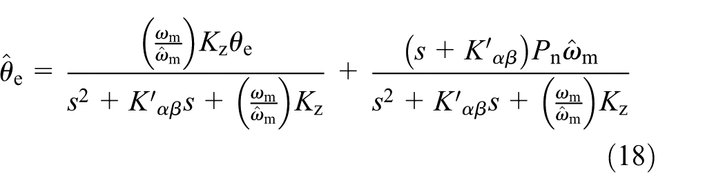
It can be seen from equations (17) and (18) that the poles and zeroes of the closed-loop transfer functions are nearly constant under different speed conditions (assuming

In this article,

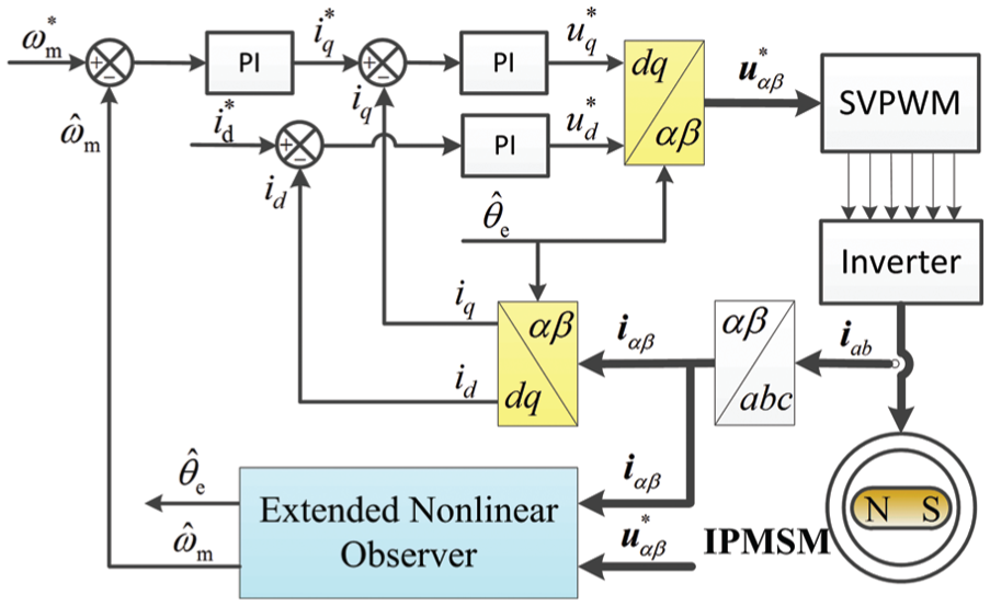
Sensorless control system for IPMSM
Figure 3 shows the block diagram of sensorless IPMSM control system based on the extended nonlinear observe, consisting of a speed proportional–integral (PI) regulator and two current PI regulators.
Block diagram of the sensorless IPMSM control system.
As shown in Figure 3, rotor speed and position are obtained through the extended nonlinear observer except for startup period where an open-loop sensorless starting method is employed instead. The q-axis current reference
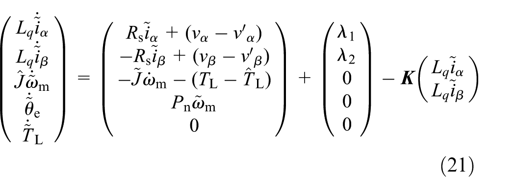
Rotational inertia adjustment strategy
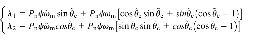
Considering the uncertainty of the system rotational inertia
where
Assuming that

It can be inferred from equation (22) that dynamic estimation errors of the speed and position will arise during the acceleration and deceleration periods relating to the rotational inertia error. To suppress these dynamic estimation errors, the rotational inertia must be online adjusted. Rotor speed estimation error dynamics can be extracted from equation (21) and rewritten as

where symbolic speed error


As clearly shown, the objective function

According to the gradient descent algorithm, the rotational inertia should be adjusted towards the negative gradient of
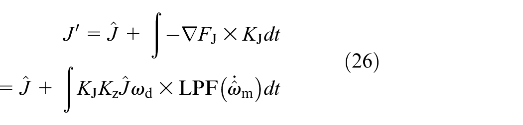
where
Considering the positive definite

This implies that the gradient descent–based inertia estimator is stable. Given that
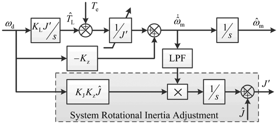
Schematic diagram of the rotor speed estimator.
Experiments and analysis
The performance of the proposed sensorless IPMSM control system is investigated on the testing platform based on DSP TMS320F28234, as shown in Figures 5 and 6.

Testing platform setup.

Photographs of the testing platform.
The sampling frequency and the pulse width modulation (PWM) frequency are both set to 10 kHz. The DC bus voltage is measured, and the reference voltage is fed to the extended nonlinear observer instead of the actual input voltage of the IPMSM. A 2500 line incremental encoder is installed to measure the actual rotor position, but only for reference purpose. The load torque is generated by a permanent magnet synchronous generator (PMSG) with a power resistor as its load. The IPMSM used in the experimental investigation has a skewed stator and asymmetric air-gap to optimize the sinusoidally distributed air-gap flux; thus, the flux harmonics are negligible and the ideal motor model can be used. And the air-gap of the q-axis is much larger than that of the d-axis; thus, the saliency ration is low. The structure of the prototype IPMSM is shown in Figure 7, and the specifications of IPMSM are given in Table 1.

Structure of the prototype IPMSM.
Specifications of IPMSM in experimental testing.
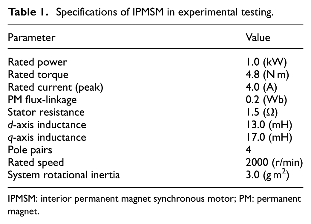
IPMSM: interior permanent magnet synchronous motor; PM: permanent magnet.
Figure 8 shows the dynamic performance of the sensorless control system of IPMSM against the step load disturbance under very low-speed operation. The speed reference is fixed to 50 r/min (2.5% rated speed), and a 4 N m (80% rated load) step load disturbance is applied and removed at 1.3 and 4.8 s, respectively. The experimental results show that the dynamic performance of the sensorless control system against load disturbance is good under such low-speed operation. Note that load torque imposed on the IPMSM is proportional to the actual speed, and the estimated load torque tracks its actual value well. The speed and position estimation errors are well damped and rapidly converge to zero.

Experimental results of the extended nonlinear observer against the step load disturbance under very low-speed operation.
Figure 9 shows the speed step responses with and without mechanical model incorporated in the nonlinear observer under no-load condition. Speed reference
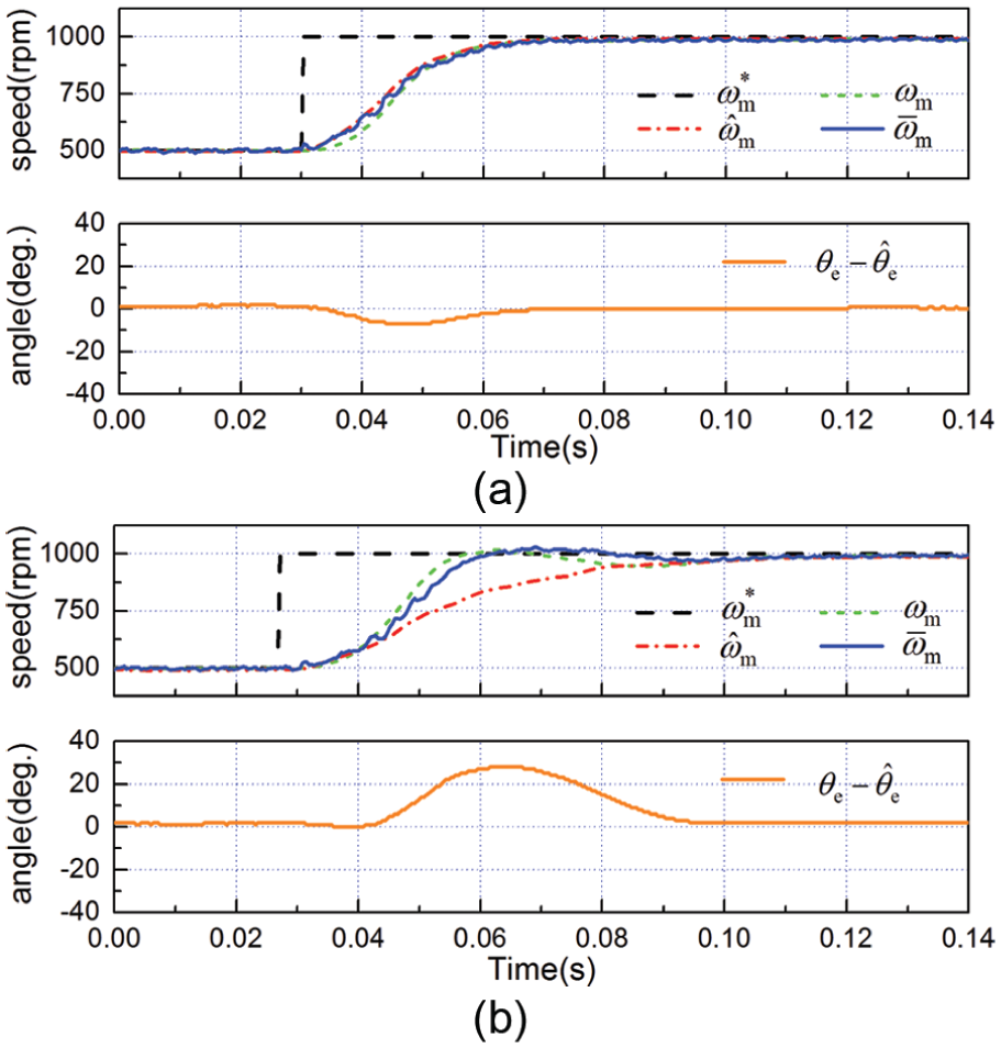
Experimental results of speed step response with and without the mechanical model incorporated in the extended nonlinear observer under no-load condition: (a) with the mechanical model and (b) without the mechanical model.
Figure 10 shows experimental results of the extended nonlinear observer with and without rotational inertia adjustment when inaccurate system rotational inertia is used in the extended nonlinear observer. The IPMSM steps from 500 to 1000 r/min and reversely under no-load condition. The electrical parameters used in the observer are accurate, while
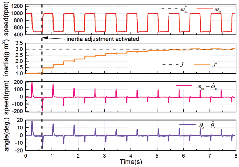
Experimental results of the extended nonlinear observer with and without rotational inertia adjustment when inaccurate system rotational inertia is adopted in the observer.
Figure 11 shows the speed tracking performance of the extended nonlinear observer with and without the rotational inertia adjustment when inaccurate rotational inertia is adopted. The IPMSM is controlled to accelerate from 500 to 1500 r/min within 0.1 s and reversely. The electrical parameters used in the observer of Figure 11(a) and (b) are accurate, while

Experimental results of speed tracking performance of the extended nonlinear observer with and without the rotational inertia adjustment when inaccurate rotational inertia is adopted: (a) without rotational inertia adjustment and (b) with rotational inertia adjustment.
Conclusion
This article proposed a high dynamic performance sensorless control scheme for IPMSM based on an extended nonlinear observer with compensation for rotational inertia uncertainty.
The extended nonlinear observer estimates rotor position, speed and load torque simultaneously and directly from stator current estimation errors. Taking into account of mechanical parameter uncertainty, explicit dynamic estimation errors of rotor position and speed have been derived based on the error dynamics of the sensorless control system. Furthermore, this control strategy, employing the gradient descent algorithm, proposed a novel online rotational inertia adjustment method for sensorless control system, and the dynamic estimation errors have been effectively suppressed. The experiments and analysis demonstrated that the proposed sensorless control strategy for IPMSM, in both transient and steady-state periods, has high performance on the estimation of position and speed.
Footnotes
Academic Editor: Teen-Hang Meen
Declaration of conflicting interests
The author(s) declared no potential conflicts of interest with respect to the research, authorship, and/or publication of this article.
Funding
The author(s) disclosed receipt of the following financial support for the research, authorship, and/or publication of this article: This work was supported by the National Basic Research Program (973 Program) (2013CB035604), the Technology Application Research Program for Public Welfare of Zhejiang Province (2015C31125) and the Natural Science Foundation of Zhejiang Province (LY14E070004).