
Abstract
The article considers the effect of joint linear and nonlinear cubic damping on dynamics of a gyroscopic rigid rotor interacting with an electric motor with a rectilinear characteristic, taking into account the nonlinear rigidity of the support material. The method of regulating the control parameter (voltage on the motor), the amplitude of vibration, and the angular velocity of the shaft in the frequency equation, depending on the value of the coefficient of nonlinear cubic damping of the support, offers the most effective options for controlling resonant oscillations of large amplitudes. It is shown that the greater the value of the coefficient of nonlinear cubic damping, the easier it is to control these oscillations. Moreover, it is proved that the Sommerfeld effect (of the first kind) can also be weakened and eliminate with the help of joint linear and nonlinear damping. To do this, in the case of a rigid characteristic of the nonlinear elasticity of the support material, in a rotor system with a nonideal energy source to eliminate the bistability region, that is, jumping effects, more nonlinear damping of support or energy from a nonideal energy source will be required than in the case of an ideal rotor system.
Keywords
Introduction
The functioning of many important and responsible vibration machines is based on the use of energy sources of various types and characteristics. There are cases when the power consumed by the oscillatory system is comparable in magnitude, with the power of the exciter-energy source called “nonideal.” The movement of the oscillatory system under the action of such sources is accompanied by the mutual influence of the energy source and the oscillatory system on each other. The interaction of an oscillatory system with an energy source should manifest itself in both stationary and nonstationary modes of motion, especially in such practically important cases as the case of the passage of oscillatory systems through resonances.
The process of passing the rotor system through critical speeds, considering its interaction with the energy source, was considered in many studies.1–11 In particular, it was found that under conditions when the power reserve of the energy source is small, the course of the process significantly depends on the characteristics of the energy source. Changes in the rotor speed turn out to be closely related to the change in vibration amplitude. As the rotor approaches the lower limit of any unstable speed range, the rotor speed is locked at that speed with increasing swirl amplitudes and the rotor speed does not respond to increased motor power unless there is enough excess power to accelerate the rotor through the corresponding unstable speed range. With such excess power, the transition from a lower limiting rate of instability to a much higher stable rate occurs as a nonlinear surge phenomenon.1–4 These symptoms, commonly referred to as the Sommerfeld effect, arise from the internal energy coupling between the drive and the driven system and are important design considerations in the design of various rotating machines with flexible supports (bearings).
Dasgupta and Rajan 5 studied the Sommerfeld effect using the steady-state amplitude obtained by the instantaneous power balance method and additionally verified by numerical simulation. It also shows the transient characteristics of the dimensionless amplitude and the speed of the shaft with time change through the resonance of the first mode. A rotor system with asymmetric bending flexibility and support bearings has many stable and unstable speed ranges. In contrast to the usual Sommerfeld effect (of the first kind), where the power deficit at resonance is the cause of velocity capture, ideally, there is no need for a residual rotor unbalance in the Sommerfeld effect of the second kind. In both cases of speed capture, excess engine power is spent on increasing swirl amplitudes. The Sommerfeld effect of the first kind refers to the resonance at a synchronous rotor vortex (critical speeds), while the second kind effect refers to the instability of the rotor vortex. 4
Due to the anisotropy in the rigid shaft supports, both forward and reverse vortex motions of the rotor are excited with an unbalanced disk with a nonideal energy source – a direct current motor (DC). 6 This causes the Sommerfeld multieffect, when two nonlinear surges appear at the first forward and reverse critical speeds during the rotor up and down coast. When the two critical speeds are close to each other, the complex phenomenon of speed lock and surge occurs. Accordingly, transitions through both resonant states are studied. First, analytical solutions are obtained under the assumption of a stationary state; then, transient simulations are performed using a link graph model (BG).
In study of Cveticanin et al., 7 two particular cases of motion depending on the frequency properties of the system were assessed. When the frequency properties in both orthogonal directions are equal, only one resonance occurs. If the frequency in one direction is twice as high as in the other, two different resonances occur: one in the x-direction and the other in the y-direction. The conditions for the surge phenomena and the Sommerfeld effect are presented.
The decomposition of the equations of motion, proposed in the article of Awrejcewicz et al., 8 allows separating the vibration of the rotor from its rotations. The presented approach can be used to separate vibration from rotation in many other mechanical and mechatronic systems. The behavior of the considered nonideal system near two simultaneously occurring resonances is studied using the Krylov–Bogolyubov averaging method. An analysis of the stability of the resonant response is also carried out.
Kafi and Hosseini 9 are studying nonlinear nonstationary vibrations of a rotating composite shaft during the passage of a critical velocity, excited by a nonideal energy source. Geometric nonlinearity, gyroscopic effect, rotational inertia, and coupling due to material anisotropy are taken into account, while shear deformation is not taken into account. Using the Hamilton principle, the equations of motion of axial, bending, torsional, and rotational motion for a composite shaft with a variable speed of rotation are obtained. The influence of external damping, eccentricity, fiber angle, the moment of resistance, and nonlinear terms and the influence of tensile-torsional coupling on the occurrence of the Sommerfeld effect are studied. It is shown that nonlinearity and coupling have a significant effect on the prediction of the Sommerfeld effect. Another article Bisoi et al. 10 studied the Sommerfeld effect in a strongly gyroscopic rotary dynamic system. The dynamics of an overhanging rotor system near the Sommerfeld effect modes is studied using a discrete and continuous shaft-rotor model in combination with a nonideal motor drive model.
A rigid rotor system driven through a universal joint (U-joint) and mounted on weakly damped flexible supports demonstrates parametric instability of the main and combined types at certain combinations of torque and speed. 11 It is shown that the dynamic coupling between a DC motor and a rotating rotor in a nonideal system can stabilize the system in speed ranges where the corresponding ideal system is unstable. This stabilization depends on constant torque/speed; that is, a motor with a higher constant characteristic tends to stabilize the system better. Input-limited and output-limited stabilization occur through repeated transitions between stable and unstable velocity regions.
Thus, if there is not enough power to overcome the resonance, then the rotor speed may stop at this resonance, or it will take a long time (or additional power) to get out of resonance; thereby damaging the system: causing failure of the rotor shaft, bearings, and other parts of the structure. Therefore, in order to stabilize the movement, it is very important to control the exit from the instability area with the Sommerfeld effect and weaken the effect with the help of vibration isolation.
Moreover, Cveticanin et al. 12 have researched the dynamics of a nonideal mechanical system that contains an engine, a nonideal source of energy, and an oscillator with a mass slowly changing in time. The system is modeled by two coupled second-order equations with time-varying parameters, in which the engine torque is assumed to be a linear function of the angular velocity. Based on the approximate averaging equations, the amplitude-frequency ratios are determined. The results of numerical solutions show that as the mass increases or decreases, the number of almost stationary positions changes. Based on the results obtained, it is proposed to develop a method for controlling motion in an oscillatory system with a nonideal mass. We would like to highlight the interesting work of Awrejcewicz and Dzyubak,13,14 in which the nonlinear dynamics of a 2-DOF rotor supported by a magnetohydrodynamic bearing was investigated using perturbation analysis. Non-resonant and various resonant cases (primary resonance with and without internal resonance) are considered. In the case of hard magnetic materials, in order to characterize the closed-loop hysteresis motion control of the rotor, the regions of instability, as well as the contours of the amplitude level of the vertical and horizontal oscillations of the rotor, are obtained in a form suitable for technical applications, that is, in the parametric plane “frequency-amplitude.”
Sghaier et al. 15 proposed a new dynamic model for unbalanced high-speed rotors with less stringent assumptions. The finite element model takes into account bending, torsion, and tension-compression, resulting in six degrees of freedom at each node. A nonideal energy source is considered and the rotor operates under nonstationary operating conditions and crosses supercritical speeds. The angular displacement is defined in such a way that it combines both its own nominal rotation and torsional deformation. The ability of the proposed model to take into account the mutual influence of transverse and torsional behavior is emphasized and demonstrated using time-frequency analysis.
The Sommerfeld effect causes instability in high-speed rotors. In the work of Goncalves et al., 16 it was found that the Sommerfeld effect depends on some system parameters and engine operation procedures. These parameters are investigated in order to avoid resonant trapping in the Sommerfeld effect. Thus, reducing this effect is extremely important for the smooth operation of the rotors at high speeds. The purpose of the article of Jha and Dasgupta 17 is to reduce the Sommerfeld effect of a system with internal damping of an unbalanced flexible shaft and disk using linearized active magnetic bearings. The characteristic equation of the fifth-order polynomial in rotor speed is obtained by balancing the energy of the input power and the mechanical power dissipated in steady state. Using MATLAB simulations, frequency responses are obtained close to system resonance for several active magnetic bearing bias currents. Thus, the Sommerfeld effect is weakened as the bias current is gradually increased. The complete disappearance of the Sommerfeld effect is also reported when the bias current reaches a certain value under certain conditions.
Recently, there has been a growing interest in nonlinear approaches in the design of vibration isolation systems.
The Sommerfeld effect can also be weakened using linear damping and nonlinear cubic damping of viscoelastic flexible rubber supports. 18
Iskakov 19 investigated the efficiency of an elastic support with linear damping and nonlinear cubic damping in resonant and nonresonant vibration regions of a rigid gyroscopic rotor with linear stiffness. It is proved that, unlike linear damping, nonlinear damping not only significantly suppresses the maximum resonant vibration amplitude but also preserves vibration isolation in the region beyond the resonant shaft rotation speed. In his next study 20 additionally takes into account the influence of the cubic nonlinear stiffness of the elastic support material on the performance of the insulator. It is shown that nonlinear viscous damping not only reduces the amplitude of high-speed vibration but also eliminates the surge effect. It turns out that if the linear damping narrows the instability area only near the resonant velocity, then the nonlinear cubic damping of the support narrows this area from all sides. It also presents the results of experimental studies of the effect of combined linear and nonlinear cubic damping of rubber support on the frequency response of the rotor, which are in good agreement with the results of analytical studies. In another article, 21 the effect of nonlinear cubic damping of elastic support on the response of an ideal rigid gyroscopic rotor system during a nonstationary resonant transition is studied and effects similar to those found for stationary oscillations are confirmed. He proposed a methodology is proposed for determining and identifying linear damping and nonlinear cubic damping of elastic support of a rigid gyroscopic rotor, in which surge effects in the frequency characteristics of a weakly nonlinear oscillating system are eliminated. 22 Al-Solihat and Behdinan 23 numerically investigated the nonlinear dynamic characteristics and characteristics of the transmitted force of a flexible rotor shaft-disk system supported by a suspension system with nonlinear stiffness and damping. The harmonic balance (HB) method, in combination with the continuation circuit, is used to determine the nonlinear frequency response and force transfer curves due to the disk unbalance force. The influence of bearing stiffness nonlinearity on the system dynamics under the support of hard and soft linear bearing stiffness and the influence of bearing damping nonlinearity are studied and compared with the influence of linear damping. The effects of linear and nonlinear vibration damping of the rubber material of the elastic support are experimentally confirmed. Therefore, in and beyond the resonant region, only nonlinear cubic damping can maintain the performance of the vibration isolator.
Review 24 has discussed the applications of nonlinearity in passive vibration control devices to provide an understanding of how nonlinearity is applied and useful in an implemented system.
In work of Joubert et al. 25 the Rayleigh scattering function is generalized so that anisotropic nonlinear damping can be introduced into the equations of motion. Using a mixture of numerical and symbolic analysis of ODEs of movement of a vibrating gyroscope (VG) for nonlinear damping of anisotropic light, we demonstrate (up to an approximate mean) that Bryan’s law is affected by any form of such damping, causing the pattern to shift, reducing the accuracy of VG.
In the article of Huang et al., 26 the study is related to the isolation characteristics of nonlinear velocity-displacement damping (VDD), which has an arbitrary nonnegative velocity and displacement exponent. Stability analysis is performed for both integer power-law damping and rational degrees of nonlinearities less than unity. The proposed damping can not only suppress the response at resonance but also improve isolation at high frequencies, if the speed and displacement parameters, as well as the damping factor, satisfy certain conditions. The VDD condition is obtained, which does not depend on the excitation amplitude. The measurement results from experimental studies are in good agreement with theoretical predictions, thereby confirming the effects of VDD during base excitation.
Lv and Yao 27 investigated a vibration isolator of systems with one degree of freedom, having nonlinear viscous damping, under force excitation. The stability of the steady-state periodic response was discussed. The effect of damping coefficients on the force transmission and displacement transmission has been studied. The results show that the performance of the nonlinear isolator has some positive effects compared to the linear isolator within a certain range.
Dong et al. 28 suggested in order to improve the efficiency of low-frequency vibration isolation of an insulator with high static and low dynamic stiffness (HSLDS), a new geometric nonlinear damping (GND) design containing semiactive electromagnetic shunt damping. GND is dependent on displacement and vibration speed, which can cause the HSLDS isolator to have different damping characteristics in different frequency ranges. The results show that the HSLDS isolator assembled with GND can meet the requirements of the isolation system under both base and force excitation, providing broadband vibration isolation and low resonant peak while maintaining high-frequency damping. Moreover, GND is superior to linear damping regardless of whether base excitation or force excitation is applied. For base excitation, GND exhibits some desirable properties that cubic nonlinear damping does not have at high frequencies.
For the first time, nonlinear damping is accurately derived from a fractional viscoelastic standard solid model by introducing a geometric nonlinearity into it. 29 The resulting damping model is nonlinear and its frequency response can be tuned with a fractional derivative according to the behavior of the material. Experiments show a strong increase in damping with the oscillation amplitude for nonlinear oscillations of plates and shells. Of the two different continuous structural elements, the free-edge plate is interesting in that it represents the case where energy does not escape through the boundary. 30
The method proposed Lisitano and Bonisoli 31 is theoretically derived to identify nonlinear damping forces depending on the degrees of displacement and velocity and is applied to identify linear and nonlinear damping matrices of a system with several degrees of freedom with a localized nonlinear magnetic damper. The coefficients of the nonlinear magnetic damping force are determined for two configurations of the magnetic damper.
The nonlinear vibration isolation system is promising for providing high-performance broadband isolation. Zhang et al. 32 created a generalized vibration isolation system with nonlinear stiffness, nonlinear viscous damping, and Bouc–Wen (BW) hysteresis damping. To evaluate the damping effect, a generalized equivalent damping coefficient with varying stiffness characteristics is determined. It has been found that the damping factor of the linear damping is related to the stiffness change characteristics, while the damping factors of the two types of nonlinear damping are related to the response amplitudes. Linear damping, hysteresis damping, and nonlinear viscous damping are suitable for small amplitude, medium amplitude, and large amplitude conditions, respectively. Hysteresis damping has the added benefit of broadband isolation.
In the article of Balasubramanian et al., 33 three different models with the same degree of freedom were compared with the same experimental data; each model has a different damping description. In particular, the models are based on modified Duffing generators with linear, quadratic, and cubic stiffness: (i) linear viscous damping; (ii) nonlinear viscoelastic dissipation described by a loss factor; (iii) standard linear solid viscoelastic model with nonlinear springs. The dissipation revealed by various models is discussed, and the main nonlinear character of damping depending on the oscillation amplitude is confirmed.
The single-degree-of-freedom linear oscillator (LO) under the influence of harmonic action is connected to a light mount, which acts, in fact, as a nonlinear energy sink (NES). 34 The strong rigidity and nonlinearity of damping in this system are provided by connecting LO and NES with two inclined linear spring-damping elements. The slope of the connecting elements during movement introduces highly nonlinear geometric effects into the forced dynamics. The analysis results show that increasing the initial tilt angle makes it possible to reduce and even completely eliminate unwanted high amplitude steady-state LO responses that coexist with desirable low amplitude-induced responses in certain frequency ranges. The presented results and associated analytical modeling can be used to design and improve the performance of nonlinear vibration absorbers as vibration reduction devices.
Mofidian and Bardaweel 35 studied the influence of nonlinear cubic viscous damping in a vibration isolation system consisting of a magnetic spring with a positive nonlinear stiffness and a mechanically inclined spring with a geometric nonlinear negative stiffness is studied. The results show that the introduction of nonlinear damping improves the performance of the vibration isolation system, eliminating the undesirable frequency surge phenomena traditionally encountered in vibration isolation systems with quasizero stiffness. Compared to a competing linear vibration isolation system, the described nonlinear system transmits fewer vibrations around the resonant peak.
In work of Lu et al., 36 a method was proposed based on measuring both the frequency of surges and the amplitudes of surges of a system subject to sinusoidal excitations, in terms of frequency and amplitude, respectively. The experimental data give frequency response curves at a fixed excitation amplitude and amplitude response curves at a fixed frequency. Based on the measured surge frequencies and displacement surge amplitudes, the system parameters can be determined by the harmonic balance method. The evaluation results show that the proposed method allows one to estimate the stiffness and damping parameters of a system with strong nonlinearities. Therefore, using knowledge about the phenomena of a nonlinear surge is a promising approach to parameter estimation.
In the article of Luongo et al. 37 the influence of nonlinear damping on the postcritical behavior of the Ziegler column is discussed. The classical double Ziegler pendulum is considered in the mode of finite displacements, in which, in addition, nonlinear damping of the van der Pol type is introduced on the hinges. The nature of the Hopf bifurcation, namely, supercritical or subcritical, and the occurrence of the phenomenon of “hard loss of stability” are investigated. Finally, the influence of nonlinear damping on the limit cycle amplitude for various linearly damped columns is studied. In study of Luongo et al., 38 the effect of linear damping on the postcritical behavior of a Ziegler column is discussed. For this purpose, the well-known double pendulum loaded at the free end with a repeating force, first introduced by Ziegler, is considered in the regime of finite displacements. It is shown that the resulting bifurcation equations are useful for providing qualitative information about the nonlinear mechanical response of the column in the entire damping plane. The verification of the asymptotic solution, carried out using numerical analysis of the exact equations of motion, indicates the effectiveness of the proposed analysis also from the quantitative point of view.
The above review clearly shows the insufficient study of the effect of joint linear and nonlinear cubic damping of support on the dynamics of a rotor system with a nonideal excitation source in stationary and nonstationary modes of motion.
Iskakov et al. 39 considered the effect of joint linear and nonlinear cubic damping on the dynamics of a gyroscopic rigid unbalanced rotor with a nonlinear rigidity of elastic support and a nonideal energy source is considered. It is proven that the combined linear and nonlinear cubic damping of elastic support can more effectively suppress the maximum amplitude and amplitude after resonant oscillations, eliminate abrupt phenomena, significantly reduce the amplitude of the oscillation frequency, and significantly narrow the unstable area until it is completely eliminated.
The purposes of this work, in contrast to the previous, are the effective control of the exit from the region of instability with the Sommerfeld effect, the weakening and the elimination of the Sommerfeld effect using nonlinear cubic support damping and the study of the effect of nonlinear cubic damping on the response dynamics of a gyroscopic rigid rotor with nonlinear rigidity of the support when interacting with a nonideal energy source with a rectilinear characteristic, both stationary and nonstationary modes of the resonant transition, including in the case of an anisotropic linear stiffness of the elastic support.
Theory/calculation
Equations of motion
A rotor system is considered, consisting of a disk and a shaft (Figure 1). A disk with mass
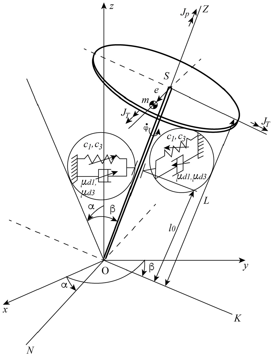
Structural diagram of the rotor.
Under these assumptions, the projections of the angular velocity on the coordinate axes of the ONKZ system can be written as follows:

Relationship between coordinates
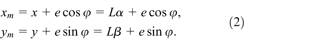
Thus, the position of the rigid shaft and the rotor as a whole in space is determined by the angles
The equations of motion of the rotor system are derived by the Lagrange method (Appendix A) from the expressions for kinetic and potential energy, the Rayleigh function, the moments of gravity, the force of inertia of the mass imbalance, and the dynamic moment of the engine:

Let us introduce the following dimensionless parameters:
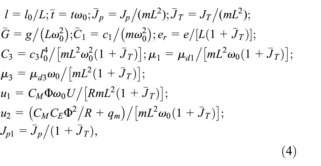
where

is the natural frequency of the rotor system (3). Using (4), we give the equations of motion (3) a compact dimensionless form:
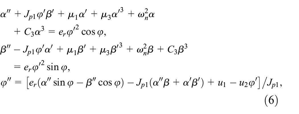
where
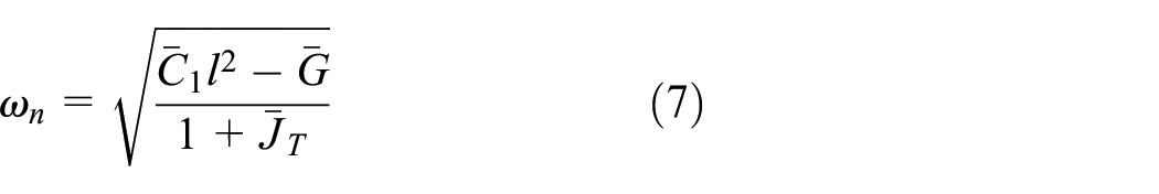
is the dimensionless natural frequency of the rotor system (6), where it is accepted

is the dimensionless dynamic torque of the engine. Here,
Here, the prime denotes the derivative with respect to the dimensionless time
We are interested in the influence of nonlinear cubic damping on the dynamics of a weakly nonlinear rotor system, taking into account the nonlinear nature of the support rigidity and the change in voltage on the motor with a characteristic taken as a straight line. 40
For the analytical solution of the equations of motion of the rotor by the Bogolyubov method,40–42 the following restrictions are accepted. Projections of moments of damping forces
After introducing a small parameter

The system of equations (6) will take the following form:
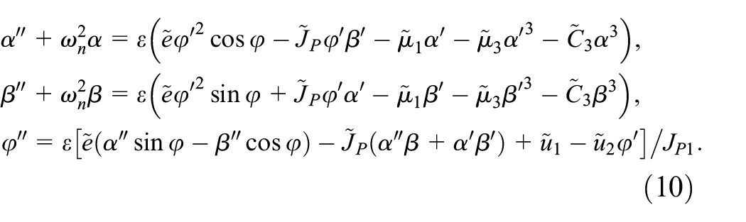
Equations (10) are a system of nonlinear ordinary differential equations of the second order with respect to
Solutions of the equations of motion
Equations (10) for
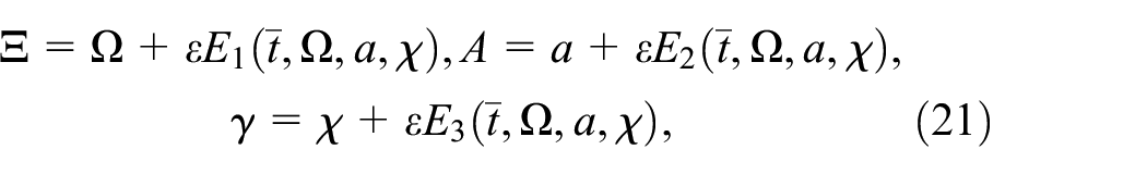
Solutions to the system of equations (10) are sought in the following form:


Here, the variables
Following Kononenko, 42 we accept new variables corresponding to the above representations:


where
Differentiating expression (11) and taking into account expression (15), we have the following:
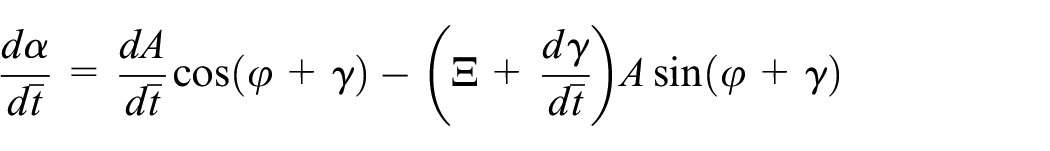
and equating it with expression (13), we obtain

Differentiating expression (13) and taking into account expression (15), we obtain
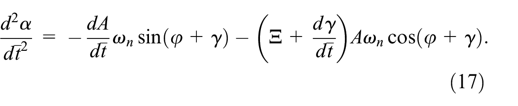
Expression (17) together with (11), (13), and (14) will be substituted into the first and third equations of system (10):

We solve equations (18) and equation (16) with respect to derivatives

The system of equations (19) is equivalent to system (10) so that the system of equations (10) is transformed as follows:

Following the Bogolyubov method,40–42 approximate solutions of equations (20) can be sought in the following form:
where
The equations of the first approximation will be obtained by averaging the right-hand sides of (20) over an explicitly specified time

After performing the averaging operation and eliminating the small parameter

Equations (23) can also be obtained using relations (12)–(15) and the Bogolyubov method40–42 as applied to the second equation of system (10).
Under conditions

from (23), we obtain equations that determine the stationary modes of motion:

From the system of equations (24), we find the equation for determining the frequency:

The expression for determining the amplitude of oscillations

Expression for determining the phase of oscillations
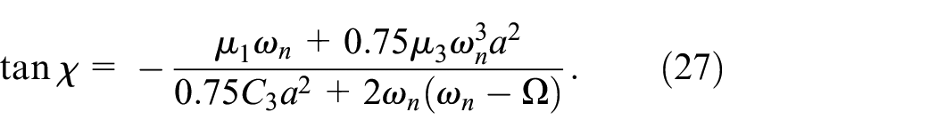
In the absence of nonlinear damping, formulas (25)–(27) completely coincide with similar results of Kononenko’s work 42 for an oscillatory system with a nonlinear restoring force.
Stability criterion
Analysis of the stability of periodic solutions is performed using approximate first-order differential equations (23), which can be written in an abbreviated form:

In the stationary state, equations (28) are equal to zero:

Taking into account the difference between the perturbed and unperturbed equations, the differential equations in variations are written as follows:

The characteristic determinant of equation (29) has the following form:

Index “0” means that partial derivatives of F are functions at the equilibrium point. The stability of approximate solutions (23) depends on the roots of the characteristic equation (30). The solutions are stable if the eigenvalues of the characteristic equation have negative real parts.
In equations (30), the partial derivatives have the following expressions:
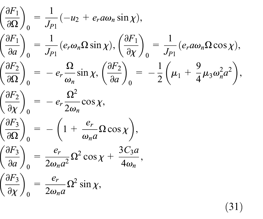
where

Equations of motion in the case of anisotropy of support flexibility
In the case of an anisotropic linear stiffness of elastic support in two mutually perpendicular directions, under the assumption that the stiffness and damping nonlinearities are small and isotropic, the nonlinear differential equations of rotor motion are derived by the Lagrange method (Appendix B) and take the following form:

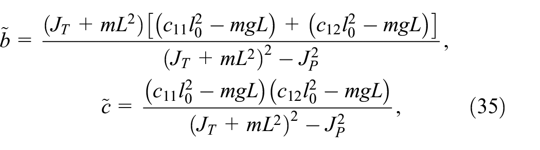
Natural frequencies (critical speeds) of a dampened rotor system (33) are as follows:
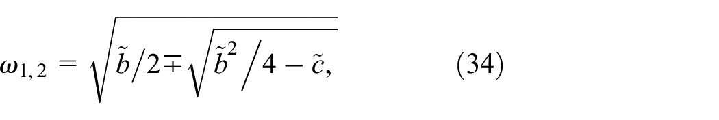
where
when
Let us introduce the following dimensionless parameters:

Using (36), the equation of motion (33) can be represented in a dimensionless form:

where

is the dimensionless natural frequency of the rotor system (37) at

is the dimensionless natural frequency of the rotor system (37) at
In the case of resonant transitions close to steady-state modes from the equations of motion of the rotor, in accordance with (37), can obtain an energy relation that determines the power spent on damping the oscillatory motion

Results and discussion
Regular fluctuations and their analysis
The numerical results were obtained using the MATLAB package (R2021a (9.10.0.1602886) 64-bit (win 61) 17 February 2021). The calculations were carried out for the system parameters with the following values: e
r
= 0.0346, ωn ≈ 1, JP1 = 0.021 (


Vibration near the main forced resonance at the coefficient of nonlinear cubic damping 0.01: (a) amplitudes and (b) angular velocity.
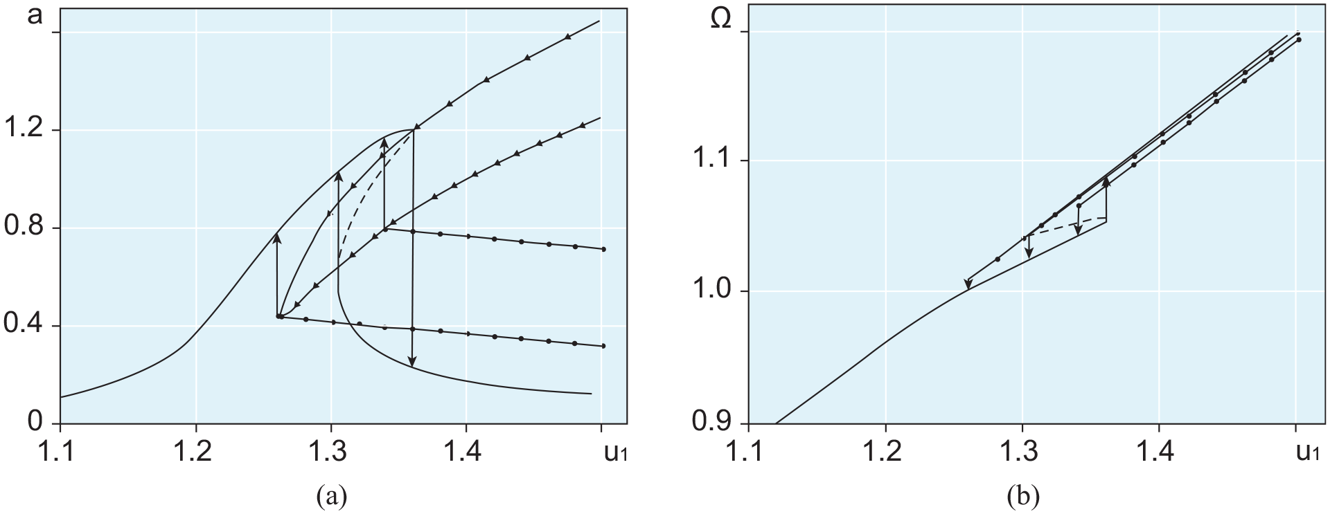
Vibration near the main forced resonance at the coefficient of nonlinear cubic damping 0.02: (a) amplitudes and (b) angular velocity.
or

and the frequency equation (25), and they are marked with small two triangles connected by a line (Figures 2(a) and 3(a)). Increasing the parameter
At the points of these transitions, the roots of the characteristic equation (30) have negative real parts. One root has no imaginary part and the remaining two have identical real parts in absolute value so small compared to unity; they can be approximately considered equal to zero.
It should be noted that natural transitions between periodic modes of motion under hopping effects also occur through the region of instability: in the case of μ3 = 0.01 at
Thus, with an increase in the coefficient of nonlinear cubic damping μ3 from a value of 0.01 to a value of 0.02 with constant linear damping with a coefficient μ1 = 0.01, the “distances” of transitions from a periodic to a quasiperiodic motion mode and vice versa decrease. This is positively reflected in the safety of these transitions and in control of oscillations of large amplitudes with the regulation of the voltage on the motor and vibration amplitude.
In Figures 2(b) and 3(b), a deviation of the dependency graph is noticed

where
Differentiating (26) with respect to

By resolving (26) and (44) together, we can find the values of the amplitude of oscillations and the speed of rotation of the shaft (or the detuning of the frequency of oscillations):
The extreme values of the oscillation amplitude can be determined from the following condition:

or

By resolving the system from equations (26) and (45), it is possible to find the maximum resonant oscillation amplitude.
In order to determine the degree and nature of the influence of the energy source on the dynamics of an oscillating system in comparison with the case with an ideal energy source, we represent the system of equations of motion of an ideal gyroscopic rotor system in the following form:
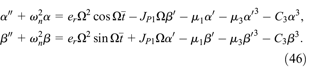
Having solved equations (46) by the method of varying amplitude, we obtain the averaged equations of nonstationary oscillations of the rotor 20 in the following form:
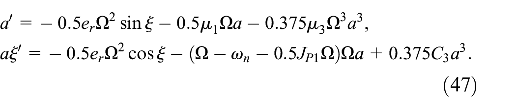
Under conditions

Acting with function (48) in the same way as in the case of a rotor system with a nonideal energy source, we obtain the expressions necessary to determine the boundaries of the bistability region and the maximum resonant oscillation amplitude, respectively:

and

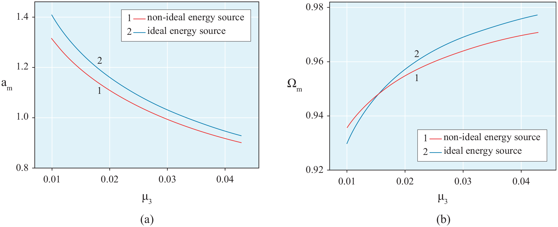
From the system of equations (48) and (49), we find the coordinates of the boundaries of the bistability region in terms of the oscillation amplitude a and the shaft rotation speed Ω; from the system of equations (48) and (50), we find the maximum resonant amplitude am and the corresponding shaft rotation speed Ωm.
The dependencies of the coordinates of the boundaries of the bistability region on the coefficient of nonlinear cubic damping for the positive and negative nonlinear coefficients of support stiffness are shown in Figures 4 and 5. Of these, it is noticeable that the case of a rigid nonlinear characteristic of the elastic support material for a rotor system with a nonideal energy source has a wider bistability area than for a rotor system with an ideal energy source, which contrasts with the case of a soft nonlinear characteristic of the elastic support material. In both variants of the nonlinear elastic characteristic of the support material, as the coefficient of nonlinear cubic damping μ3 increases, the area of bistability narrows and when certain values of μ3 are reached, it will disappear. The bistability region of the rotor system with a negative nonlinear support stiffness coefficient with the value C3 = –0.1 is located in the speed range below the natural oscillation frequency ωn, and the rotor system bistability region with a positive nonlinear support stiffness coefficient C3 = 0.1 is located in the speed range above the natural frequency oscillations ωn of system (6).

Dependencies of oscillation amplitude (a) and shaft rotation speed (b), corresponding to the boundaries of the bistability region, on the coefficient of nonlinear cubic damping at a non-linear rigid characteristic.

Dependencies of the oscillation amplitude (a) and shaft rotation speed (b), corresponding to the boundaries of the bistability region, on the coefficient of nonlinear cubic damping at a non-linear soft characteristic.
It should be noted that in vibrating nonideal systems, the most common case is with a positive value of the coefficient of nonlinear stiffness C3 > 0 of the support material, that is, with a bistability region located behind the natural oscillation frequency ωn. In this case, a rotor system with a nonideal energy source, to eliminate the bistability region, that is, jumping effects, will require more nonlinear cubic damping of support or energy from a nonideal energy source than in the case of an ideal rotor system.
The dependencies of the maximum amplitude of the frequency response of the rotor system on the coefficient of nonlinear cubic damping for the cases of hard and soft characteristics of the nonlinear elasticity of the support are shown in Figures 6 and 7. It is easy to see that with an increase in the value of the coefficient of nonlinear cubic damping μ3, a significant decrease in the maximum amplitude am of the resonance curves and the approximation of the corresponding shaft rotation speed Ωm to the natural frequency of the system ωn ≈ 1, in the case of a rigid characteristic of the nonlinear elasticity of the support material from the side of the larger from ωn the speed of rotation of the shaft, in the case of a soft characteristic of the nonlinear elasticity of the support material from the side of the shaft rotation speed Ωm that is less from ωn.

Dependencies of the maximum resonant oscillation amplitude: (a) and the corresponding shaft rotation speed and (b) on the coefficient of nonlinear cubic damping with a nonlinear rigid characteristic.
Dependencies of the maximum resonant oscillation amplitude: (a) and the corresponding shaft rotation speed and (b) on the coefficient of nonlinear cubic damping with a nonlinear soft characteristic.
In a nonideal rotor system with a support material with C3 > 0, due to the strong interaction of the system with the energy source, the acquisition of additional energy by the system from the source for a steep increase in the response amplitude at a practically unchanged shaft rotation speed and the maximum amplitude of the frequency response is greater than in an ideal rotary system, the same value of C3 support material.
Nonstationary resonant transition and their analysis
Now consider the nonstationary transition of the rotor through the resonant region with a “slowly” time-varying control parameter
The approximate equations of rotor motion (23) were modeled in the MATLAB -Simulink package (R2021a (9.10.0.1602886) 64-bit (win 61) 17 February 2021).
Damping parameters have the following values: μ1 = 0.01; μ3 = 0.01, 0.02. The control parameter
The values of the parameters for the initial conditions are borrowed from the frequency characteristics of the stationary oscillation for Ω0 < ωn and Ω0 > ωn.
For C3 = 0.1 (rigid nonlinear characteristic of the elasticity of the support), we choose the initial conditions for the case ν = 0.00025:
With C3 = –0.1 (soft nonlinear characteristic of the elasticity of the support), we accept the following initial conditions for the case: ν = 0.00025:
Dependency graphs

Transition through resonance: (a) amplitude and (b) angular velocity, in the case of a nonlinear rigid characteristic with a slowly increasing value of the control parameter.

Transition through resonance: (a) amplitude and (b) angular velocity, in the case of a nonlinear rigid characteristic with a slowly decreasing value of the control parameter.

Transition through resonance: (a) amplitude and (b) angular velocity, in the case of a nonlinear soft characteristic with slowly increasing control value parameter.

Transition through resonance: (a) amplitude and (b) angular velocity, in the case of a nonlinear soft characteristic with a slowly decreasing value of the control parameter.
From these figures, the damping effect of the parameter is primarily evident
The values of the maximum amplitude and the corresponding control parameter and shaft rotation speed in the resonance curves during acceleration (Figures 8 and 10) and run-out (Figures 9 and 11) of the rotary machine approximately determine the positions of the jumping effects. As the coefficient of nonlinear cubic damping increases, the distance between these positions decreases (the displacements of these positions in Figures 8 and 11 are much larger than in Figures 9 and 10), and its further increase can completely eliminate jumping phenomena.
Thus, with an increase in the nonlinear cubic damping, the Sommerfeld effect with a nonlinear jump can be significantly weakened up to its complete elimination. 43
A change in the characteristic of the nonlinear stiffness of elastic support significantly affects the description of the dependency graphs
After the transition of the amplitude peak with a slow change in the control parameter and the shaft rotation speed, the amplitude of the system response, having made damped oscillations, tends to certain values, regardless of the values of the coefficient of nonlinear cubic damping.
To verify the reliability of the process of transition through resonance, from equation (26), assuming to be equal to zero the expression

where
The maximum amplitudes and the corresponding shaft angular velocities and the control parameters of the resonance curves approximately satisfy equations (51) and (25). With system parameters ωn ≈ 1, JP1 = 0.021, μ1 = 0.01, ν = 0.00025, correspondences between numerical (graphical) values of the maximum amplitude
Correspondence between oscillatory characteristics: numerical (graphical) values maximum amplitude, resonant values of rotation speed, and control parameter according to equations (51) and (25).

The values of oscillation parameters given in Table 1 completely coincide with the analytical results of solving equations (26) and (25).
For comparative analysis, we present the solutions of the system of equations (47) with previously known initial parameters of the system in the form of dependency graphs
Transition through resonance with a slow increase in the rotation speed in cases of non-linear (a) hard and (b) soft characteristic.
and a similar Table 2 for a rotor with an ideal energy source.
Correspondence between oscillatory characteristics: numerical (graphical) values of maximum amplitude, resonant values of rotation speed according to the backbone curve equation (52).

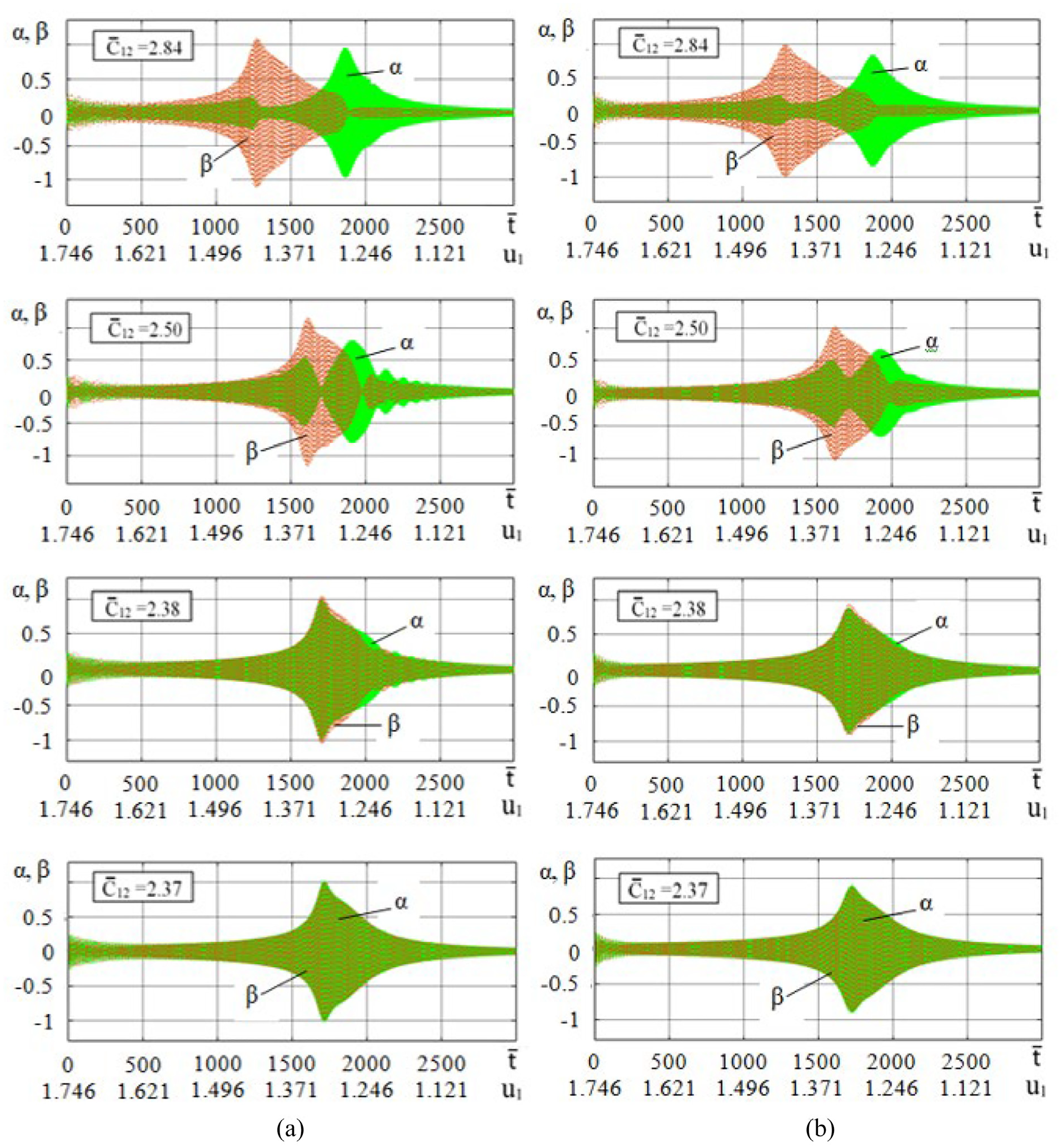
In formula (52),
By comparing the tabular values of the maximum amplitude and the corresponding shaft rotation speed at different values of the coefficient of nonlinear cubic damping for cases with a nonideal source and an ideal energy source, one can verify the reliability of the previously given conclusions.
Expressions (44) and (49) without frequency response equations (26) and (48) determine the boundaries of the instability regions for the cases of a rotor with nonideal and ideal energy sources. The boundaries of the instability region constructed according to the stability criteria (44) and (49) at the value of the linear damping coefficient μ1 = 0.01 and different values of the coefficient of nonlinear cubic damping μ3 are shown in Figure 13.

The boundaries of the region of instability at the coefficient of nonlinear cubic damping: (a) 0.01 and (b) 0.02: (1) the case of a nonideal energy source and (2) the case of an ideal energy source.
In both cases, as the value of μ3 increased from 0.01 to 0.02, the instability regions narrowed. It is clearly seen that in the case of an ideal energy source, the dimensions of the instability region along the Ω and a axes are noticeably smaller than those in the case of a nonideal energy source; this is more distinct at μ3 = 0.02.
With a further increase in the value of μ3, the dimensions of the instability region decreased: in the case with a nonideal energy source along the a axis, along the Ω axis from the side of the origin, and in the case with an ideal energy source along both axes comprehensively. The regions of instability disappear: in the case of an ideal energy source at μ3 = 0.03788; in the case of a nonideal energy source at μ3 = 0.0565.
The power consumed for damping the oscillatory motion can be obtained from equation (25) by multiplying it by Ω:

On the other hand, the power of the energy source and the power expended to overcome the forces of resistance to the rotation of the motor rotor are as follows:

From previous studies, it was found that the greater the probability of interaction with an energy source in the resonant region, with a slow increase in the speed of rotation of the shaft, the amplitude of oscillations increasing steeply, and in order to suppress oscillations with large amplitudes in accordance with (47) and (48), the more the damping and power of the energy source ((53) and (54)).
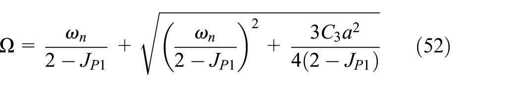
To confirm the analytical studies, equations (10) were solved directly numerically using the MATLAB-Simulink package (R2021a (9.10.0.1602886) 64-bit (win 61) 17 February 2021). Figure 14 shows the obtained numerical results in the form of dependency graphs

Transition through resonance with ν = 0.00025 according to the results of the numerical solution of equations (10) for non-linear: (a) hard and (b) soft characteristic.
An analysis of these oscillograms shows that with increasing the coefficient of nonlinear cubic damping, the maximum and beyond the maximum oscillation amplitudes decrease. Oscillations in the region behind the resonance have the character of damped beats, which are more pronounced for small values of the coefficient of nonlinear cubic damping than for large values. The difference between Figures 8(a), 10(a), and 14 lies in the magnitude of the maximum amplitude and its corresponding value of the control parameter, but the basic behavior of the transient through resonance remains the same.
Now, for a comparative analysis of the results of direct modeling of the equations of motion of a nonideal and ideal system, we present in Figure 15 results of numerical solution of equations (46).

Transition through resonance with ν = 0.00025 according to the results of the numerical solution of equations (43) for non-linear: (a) hard and (b) soft characteristic.
From the oscillograms in Figures 14 and 15, it can be seen that the response amplitudes (including maximum amplitude) of a nonideal system in the transition region are much greater than the vibration amplitudes of an ideal system, which is the result of a strong interaction of the vibrating rotary machine with the engine in the shaft speed region
Damped beats observed in Figures 8 to 12, 14, and 15 occur due to the superposition of forced nonstationary oscillations and damped natural oscillations with frequencies that closely coincide with the vicinity of the resonance. 22
According to equations (10), the direct modeling results can also be provided in the form of phase trajectories

Phase trajectories: (a) C3 = 0.1, μ3 = 0.01, (b) C3 = 0.1, μ3 = 0.02, (c) C3 = −0.1, μ3 = 0.01, and (d) C3 = −0.1, μ3 = 0.02

The configuration space (beta, alpha): (a) C3 = 0.1, μ3 = 0.01, (b) C3 = 0.1, μ3 = 0.02, (c) C3 = −0.1, μ3 = 0.01, (d) C3 = −0.1, μ3 = 0.02.
Increasing value
For numerical calculations by (37), some geometric and dynamic parameters of the gyroscopic rotor system are taken from the experimental setup: L = 0.46 m, l0 = 0.33 m, m = 2 kg, c11 = 2 104 N/m, c12 = 2.4 104 N/m, JT = 0.090 kgm2, JP = 0.011 kgm2, e = 0.0193 m used in study. 20
Now, according to formula (34), taking into account (35), it is possible to calculate the natural frequencies (critical speeds) of the gyroscopic rotor system (33): ω1 = 64.94 s−1, ω2 = 71.34 s−1.
Dependencies ω1 and ω2 from c12 at constant c11 are shown in Figure 18. Hence, a noticeably weak dependence of ω1 on c12 and ω2 decreases as c12 decreases, approaching the value of ω1.

Dependences of critical speeds on the linear stiffness of the support material.
The angular speed of rotation of shaft ω1 in the interval [64.95, 64.48] can be approximately considered constant and equal to ω1 = 65 s−1. This allows dimensionless parameters
Calculation by formulas (36), (38), and (39) will provide the following values of dimensionless parameters:
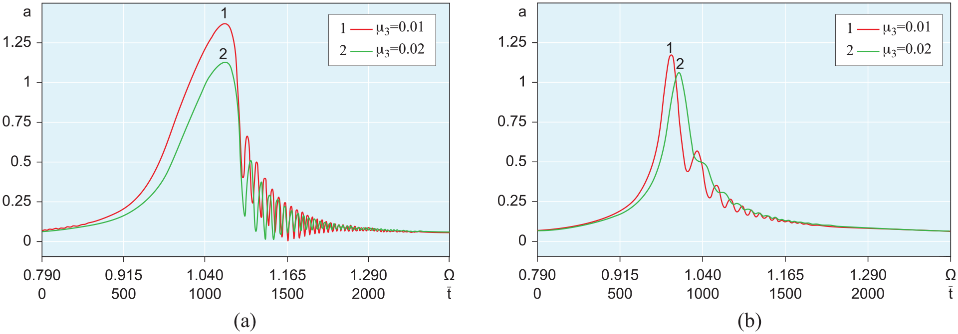
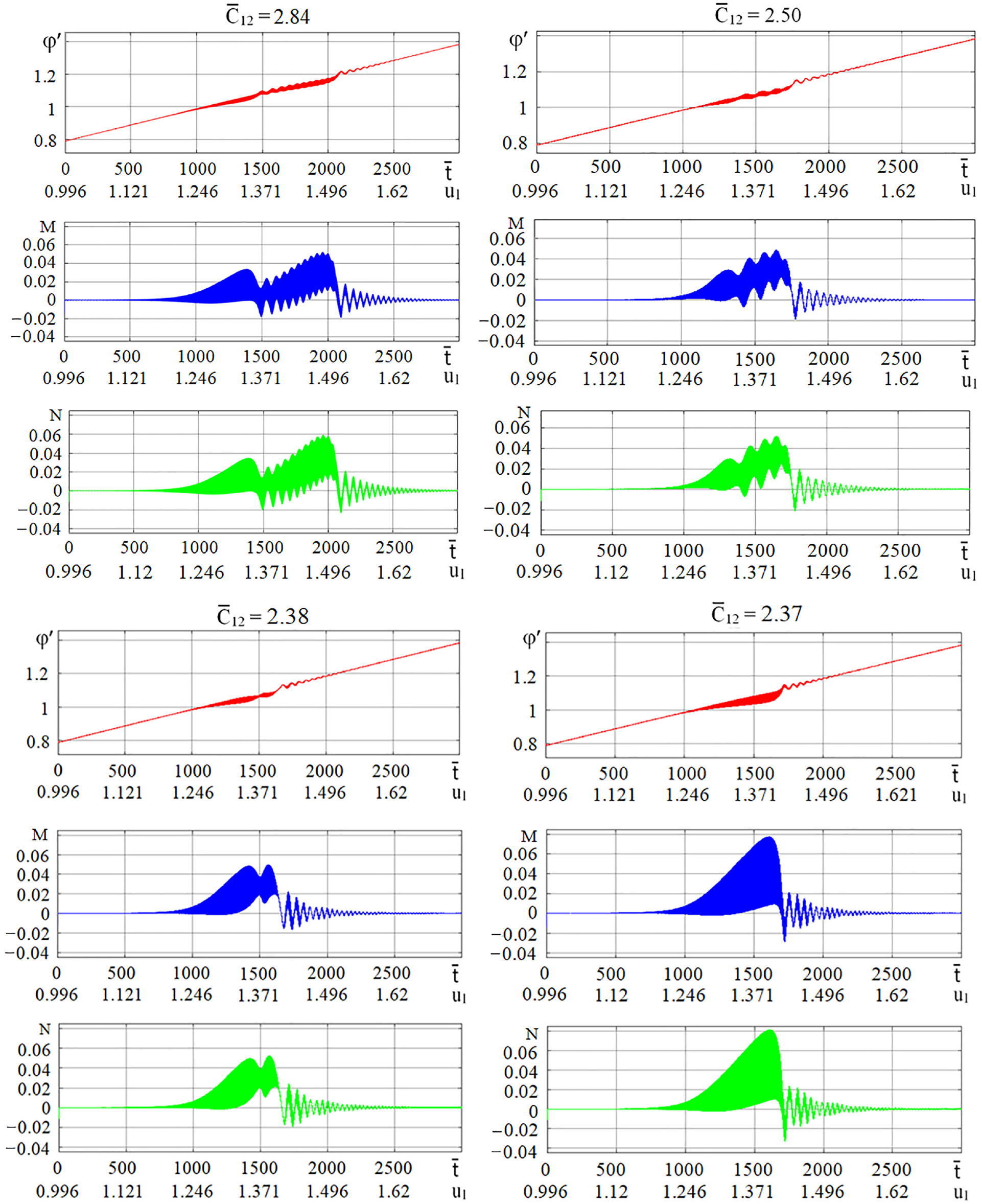
Figures 19 and 20 show waveforms α = α(u1) and β = β(u1) at

Oscillograms of angular coordinates α and β at
Oscillograms of angular coordinates α and β at
Control parameter
To simulate a direct resonant transition, the initial conditions are taken for sufficiently small angular coordinates α and β of stationary vibrations, under which the anisotropy properties of the support material rigidity practically do not manifest themselves:
At a slowly increasing parameter
In the oscillograms α = α(u1) of Figure 19, two resonance regions are well noticed, first resonance region in terms of manifestation area and maximum amplitude of oscillations prevails in them, and the second small resonance region is observed in the beating region. In the oscillograms β = β(u1) of Figure 19 in terms of manifestation area and maximum oscillation range the second resonance region prevails. When the value
A nonlinear jump from a large amplitude of oscillations to a smaller amplitude is observed in the first resonance region of the oscillogram α = α(u1) and the second resonance region of the oscillogram β = β(u1). If runout in oscillograms α = α(u1) is observed after the jump effect, in oscillograms β = β(u1) – in the region with the control parameter
A comparative analysis of the corresponding oscillograms in Figure 19(a) and (b) shows that nonlinear cubic damping significantly suppresses the amplitudes of oscillations in the resonance regions and in the runout region, especially in the oscillograms α = α(u1) in the interval
When choosing the initial conditions to simulate the reverse resonant transition the equations of motion (51), we took into account the results of solving the same equations for a direct resonant transition. Thus, the initial conditions for μ3 = 0.01:
At a slowly decreasing parameter
From the oscillograms α = α(u1) in Figure 20, two resonant positions are clearly visible with the rotor machine runout and at the values
Graphic dependencies of the angular speed of rotation of the shaft on the control parameter:
Dependences of the rotation speed, dynamic torque and power of the motor shaft on the increasing control parameter at the coefficient of nonlinear cubic damping 0.02.

Dependences of the rotation speed, dynamic torque and power of the motor shaft on the decreasing control parameter at the coefficient of nonlinear cubic damping 0.02.
In Figure 22, the positions and magnitudes of the maximum amplitude in the resonant regions correspond to nonlinear jumps from a smaller amplitude to a larger one with decreasing values
Thus, during the acceleration of the rotary machine, due to the anisotropy of the linear stiffness of the support material, the two critical speeds that appear are so close to each other that the exit from the first resonance at a lower speed can lead to capture at the second resonance at a higher speed, the power acquired by the system in the second resonant region is several times greater than that in the first, at least comparable. In a significant range of values of the control parameter or shaft rotation speed, the severity of the Sommerfeld effects is significant. In both resonant regions of speed capture, excess engine power is spent on increasing the amplitude of oscillations of angular (linear) displacements. Therefore, the isotropy of the linear stiffness of the support material is a desirable property for designing a vibration isolator of the machine.
Subsequent to the results of present and previous studies, and on the basis of the model developed in work of Iskakov and Bissembayev
20
3D, a prototype of a centrifuge installation based on a gyroscopic rigid rotor (Figure 23) and the structure of its elastic support (Figure 24) were created for which a patent request for invention was filed. The installation consists of the main parts: the rotor bowl, the shaft, the motor, the lower hinged and the upper elastic support and the outer housing attached to the platform. The rotor is made in the form of a cylindrical bowl to satisfy the condition

Centrifuge based on vertical rigid gyroscopic rotor: 1 – rotor bowl, 2 – electric motor, and 3 – control panel.

Elastic support structure: 1 – rubber plate, 2 - coupling, 3 – rotor shaft, and 4 – bearing.
Conclusion
Differential equations of motion of a gyroscopic rigid unbalanced rotor with nonlinear cubic damping and nonlinear rigidity of elastic support are constructed, taking into account the interaction with a nonideal energy source. These equations were solved by Bogolyubov’s asymptotic method and numerical methods.
In the constructed graphic dependencies of the amplitude of oscillations and the speed of rotation of the shaft on the control parameter, possible options for controlling resonant oscillations of large amplitudes are given, including the most effective, by the method of controlling the control parameter (voltage on the motor), the vibration amplitude, and the angular velocity of the shaft in the frequency equation.
It is proved that in the case of a rigid characteristic of the nonlinear elasticity of the support material, in a rotor system with a nonideal energy source, in order to eliminate the bistability region, that is, jumping effects and weakening of the Sommerfeld effect, more nonlinear cubic damping of the support or energy from a nonideal energy source is required than in the case of an ideal rotor system.
It is shown that during the resonant transition, the nonlinear cubic damping of the support significantly suppresses not only the vibration with the maximum amplitude but also the resonant damped beating of such vibrations. It shifts the control parameter and the angular velocity of the shaft corresponding to the maximum amplitude with a rigid nonlinear elastic characteristic of the support material toward a decrease and with a soft nonlinear elastic characteristic of the support material toward an increase.
The effect of the nature of the nonlinear stiffness and the anisotropy of the linear stiffness of the support material on the maximum oscillation amplitudes with Sommerfeld effects and the corresponding control parameters (shaft rotation velocities) with increasing and decreasing control parameter is studied.
There is an agreement between the results of analytical solutions and numerical solutions of the rotor motion equations for transient processes.
The research results can be used in scientific research and design calculations to create elastic supports with the best damping parameters for a vibrating gyroscopic rotary machine.
Footnotes
Appendix A
The equations of motion of the rotor can be represented in the form of the Lagrange equations of the second kind. To do this, we first compose the expression for the kinetic energy of the disk:
Sloping that
The projections of the moments of gravity and the force of inertia of the mass imbalance have the following form:
where
The rotor receives excitation from a nonideal energy source, a DC motor.
For engine dynamic torque in accordance with Kononenko, 42 we have the expression following:
where
The basis for calculating the characteristics of the engine is the dependencies of the electromotive force of the armature
where
Electrical constant
At any constant angular velocity of the motor shaft, the applied voltage
From (A7), we find the value
The elastic support of the upper bearing of the gyroscopic rotor can be made of nonlinear materials, such as rubber, rubber, and other polymers, which are widely used as vibration dampers. As is known, rubber shock absorbers have both nonlinear damping and nonlinear stiffness.45,46 Therefore, the moments of dissipative forces acting in elastic support can be described by the Rayleigh function, in the following form:
where
where
We represent the Lagrange equations of the second kind for the rotor system in the following form:
Here, bobbed coordinates
Substituting expressions (A1), (A2), and (A8) – (A10) into (A11) and discarding perturbations containing
On the right side of the resulting system of equations (A12), the projections of the moment of gravity were also neglected since, for a rapidly rotating rotor,
Appendix B
For the case of elastic support material with anisotropic linear stiffness and isotropic cubic nonlinear stiffness, elastic forces in mutually perpendicular directions coordinates are
where
Substituting expressions (A1), (A2), (A8), (A9), and (B1) into (A11) and assuming the assumptions given in Appendix A regarding the resulting nonlinear differential equations by their simplification, we obtain
Handling Editor: Chenhui Liang
Declaration of conflicting interests
The author(s) declared no potential conflicts of interest with respect to the research, authorship, and/or publication of this article.
Funding
The author(s) disclosed receipt of the following financial support for the research, authorship, and/or publication of this article: The work presented herein was conducted with the financial support of the Science Committee of the Ministry of Education and Science of the Republic of Kazakhstan (Grant No. AP08856763).
Supplemental material
Supplemental material for this article is available online.
References
Supplementary Material
Please find the following supplemental material available below.
For Open Access articles published under a Creative Commons License, all supplemental material carries the same license as the article it is associated with.
For non-Open Access articles published, all supplemental material carries a non-exclusive license, and permission requests for re-use of supplemental material or any part of supplemental material shall be sent directly to the copyright owner as specified in the copyright notice associated with the article.