
Abstract
To achieve high quality of sculptured surface, a five-axis machine center must have excellent dynamic behavior. This article gives a new way to characterize and present the performance of machine center on milling sculptured surface which is constrained by the dynamic stiffness. First, the formation mechanism of surface quality is explained in intermittent milling process. It is mainly affected by the vibration frequency of cutting behavior. Second, the concept of dynamic stiffness of machine center is proposed and calculated based on the movement of multi-axis. To elaborate such effect, the map of dynamic stiffness on a sculptured surface, S part is obtained. The change of stiffness causes the different vibration frequency and then leads to different surface quality. Finally, experiments are conducted on S part by microscope and the waviness measurement. The results demonstrate the proposed method is very close to the true one. Presenting, measuring, and controlling the surface quality are easy for the user to understand the challenging performance of the machine center on milling sculptured surface.
Introduction
The five-axis machine tool is widely used in the manufacturing of sculptured surface because of more flexible position of the tool. Due to the complex motion of multi-axis, the dynamic behavior of the machine center becomes more and more important. Researches show that the requirement of higher surface quality has limited some operations of five-axis machine tools. 1 Either the supplier or the user needs to understand the challenging performance of the machine center on sculptured surface.
As for the contributions of various error sources in machine tool, Andolfatto et al. 2 evaluated servo, geometric, and dynamic error sources on volumetric errors of five-axis machine tool. Results show that the dynamic deformation associated with cutting forces greatly affects the surface precision. Therefore, for a long time, the stability of dynamic behaviors was paid more attention. Altintaş and Budak 3 and Smith and Tlusty 4 gave the relationship between the processing parameters and stability lobes. Heisel and Milberg 5 also proposed a method of identification of the chatter vibration from surface measurements. Thus, the chatter behavior can be calculated in advance to avoid this situation.
However, the satisfied surface quality seems not feasible to obtain. Even not on chatter, the sculptured surface is prone to defects in some places. Generally, the stiffness performance of the machine tool is characterized as the anti-deformation capacity. Budak 6 proposed an analytical method where only the deflection of the tool is concerned. For accurate analysis of the deflection, Salgado et al. 7 found in the experiment that the deflection of machine components could reach over 50% of the total deflection compared to the defection of the tool. Therefore, the dynamic stiffness of the machine tool is necessary to be calculated, not only including the tool spindle but also the motions of the five axes.
Besides knowing the anti-deformation capacity of the machine tool, users are more concerned about the mechanism by which the surface defect could occur. Zhang et al. 8 found that the vibration frequency and the spindle speed play important roles in the wavelength and amplitude of the surface. Jung and Oh 9 analyzed the influence of the feed rate, which affects the tool deflection and leads to surface waviness. By measuring the cutting force, speed of the spindle, and waviness of the surface, Liu et al. 10 found a relationship between the amplitude of waviness and the cutting parameters. However, the above results are known based on the specific model or condition. To generally predict the possible surface quality, the complete model including machine and the tool and further study about the mechanism of surface forming are needed.
In this article, the formation mechanism of milling surface quality is fully described, which are mainly affected by the dynamic stiffness of machine center in the process. Although other factors, such as geometric error, thermal drift, and Numberical Control (NC) strategies could also affect surface quality, these factors can be greatly reduced with sophisticated error compensation or optimization algorithms on modern machine tool.11,12 The study aims on obtaining the dynamic performance of machine tool on milling sculptured surface. A sculptured surface, S part is given as a case study to illustrate the proposed method. Finally, S part is measured by the instruments to validate the analysis results. The results demonstrate the limits performance of machine center on machining sculptured surface.
Development of surface quality on milling process
Formation mechanism of surface
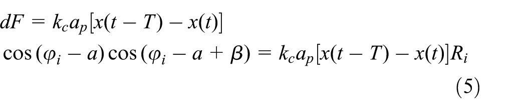
As shown in Figure 1, during the milling on finish surface, due to the intermittent behavior of multiple teeth of the tool, the second tooth may wipe out part of the surface that developed on the first tooth. Then, the third tooth could wipe out part of the area that was generated during the first and second tooth. The contact frequency and phase angle determine the overlap area of the milling process, which influences which surfaces to be wiped out. The solid lines in Figure 1 represent the actual surface left after milling by three teeth. The actual interval of waviness of T3 is larger than the waviness of T1 generated during the first-time milling. So, the surfaces of workpiece may become worse.

Surface forming on intermittent milling process.
Model of intermittent milling process
As shown in Figure 2, the cutter tooth i starts at point A and finishes cutting at point B. The normal direction of the vibration is along m-m, the direction angle is

Milling process between cutter and workpiece.
Suppose that the machining mark formed on the workpiece surface as

Thus, the mark formed during the last sub-step is

where T is the cycle time of the single tooth processing and

According to the reference X, the dynamic milling force is proportional to the cutting area. It can be expressed as

where
where

Thus, equation (4) is updated to be

Finally, the dynamic model of the machining system is

where M, C, and K, respectively, represent the equivalent mass, damping, and stiffness of the machine tool at the tool tip.
Suppose that

Substitute
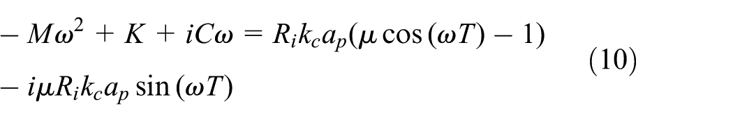
Compare the real and the imaginary parts in equations (9) and (10), so

This can be expressed as

The trigonometric function can also be expressed as a series expansion as

Substitute equation (13) into equation (12) to obtain

Equation (14) describes the relationship between the vibration frequency and system parameters. The series H is calculated by the parameters of the vibration systems, which is known to be

Dynamic stiffness of machine tool
Composed stiffness matrix
The stiffness is characterized as the anti-deformation capacity of the machine tool. During the processing, the stiffness of machine tool changes with the motions of axes. So, it is called dynamic stiffness and composed of two parts as

where
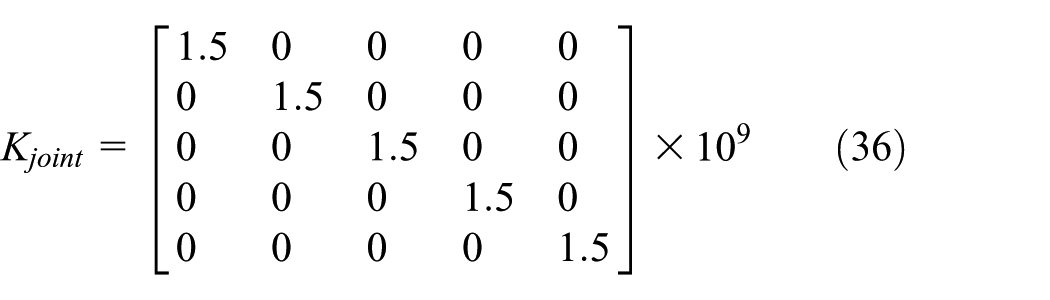
The machine stiffness

where
Similarly, the tool’s stiffness matrix is

where

Calculation on the Jacobian matrix
The Jacobian matrix depends on the topological structure of the machine. Take the AB rotary axes of a machine tool for an example, as shown in Figure 1. The machine body has the part number B0, which has the fixed coordinate system. The workbench is on the body of the machine, which can move along the track of the X-axis and have the part number B1.Two translational axes Y and Z are also on the body of the machine along another kinematics’ chain, which have the part numbers B2 and B3, respectively. Then, two rotary axes A and B with part numbers B5 and B6, respectively, are on the translational axes. Finally, the spindle is on the rotary axis with the cutting tool.
To calculate the Jacobian matrix

Similarly, the transform matrices between other driving axes are given as

Second, calculate the transform matrix R from each driving axis to the body of the machine. According to the multi-body kinematic theory, the transform matrix between the coordinate system
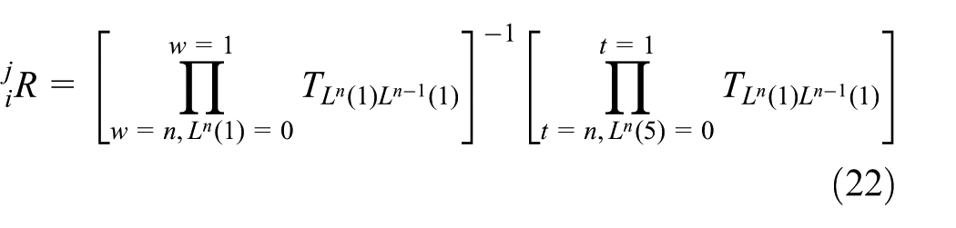
Based on the topological structure in Figure 3, the transform matrix


Topological structure of the AB rotary axes of machine tools.
Third, calculate the elements of the Jacobian matrix. Assume that the elements in transform matrix

Here,


For the tool coordinate system, the origin is at the end-tool holder. Z-axis of the tool is first downward and perpendicular to the workbench. X-axis is in same direction of X-axis of the machine tool. When the tool rotates, Z-axis is always along the tool body and X-axis rotates along the corresponding directions. The Jacobian matrix

Select the elements of the first three rows and first three columns of matrix R to form

Projection of the stiffness in the normal direction
During machining, the stiffness of the surface in the normal direction mainly affects the dynamic behavior of the workpiece. Thus, the obtained comprehensive stiffness of the machine tool needs to be projected along the normal line. The calculation process is shown as follows.
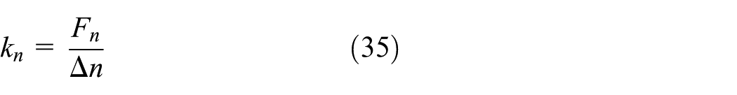
First, calculate the flexible matrix

Second, calculate the unite force matrix

where

where
Third, transform the effect of the rotary angle into an equivalent translational displacement. For a unit force, the machine tool has three translational displacements and three angular displacements, such that


Equivalent translational displacement analysis.
Thus, the equivalent translational displacements are known as

Finally, calculate the stiffness of the machine tool in the normal direction. The displacements in the normal direction are obtained by the dot product of the normal direction

Here,
Case study
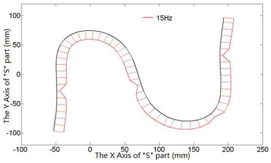
The acceptance of part precision is a key section in the acceptance of performance of a machine tool. Wang and colleagues15,16 proposed a new test S part just for a five-axis machine tool. S part presents more features of three-dimensional (3D) complex surfaces with variable curvature and different continuity and covers more positions and orientations of the tool. Up to now, S test part has been used in many machine tool builders and consumers to find the potential defects of the machine tool. In this article, S part is used to illustrate the effect of dynamic characteristics of a machine tool. Figure 5a is a 3D view of the S part. The engineering drawing of the S part is shown in Figure 5b.The shape of S part looks like the letter “S,” but it is real different. It is composed of two B-spline curves that are developed into the surface. The modeling process of S part can be found in Wang et al. 15

Three-dimensional view of the S part.
Dynamic stiffness of machine tool on cutting S path
For a specific AB rotary axes machine tool V51030ABJ, the stiffness matrix of five axes

Substitute the NC command of the S part into equations (17) and (18) to calculate the Jacobian matrices

Convert the dynamic stiffness along normal line.

Normal stiffness of machine tool on S part.
S part surface formation
Selecting 57 points uniformly distributed in S part path, substitute the equivalent stiffness of the machine tool into equation (14). Fagan 17 and Sims et al. 18 have noted that the low-order frequency of vibration mainly affects the micro-shape of surface. So, the first-order frequency is obtained in Table 1. Results of Table 1 are plotted in Figure 8 along S part path. The frequency at different positions is not consistent. Some locations such as points 7, 30, 42, and 51 are with low values.
Dynamic frequency of the machining mark.
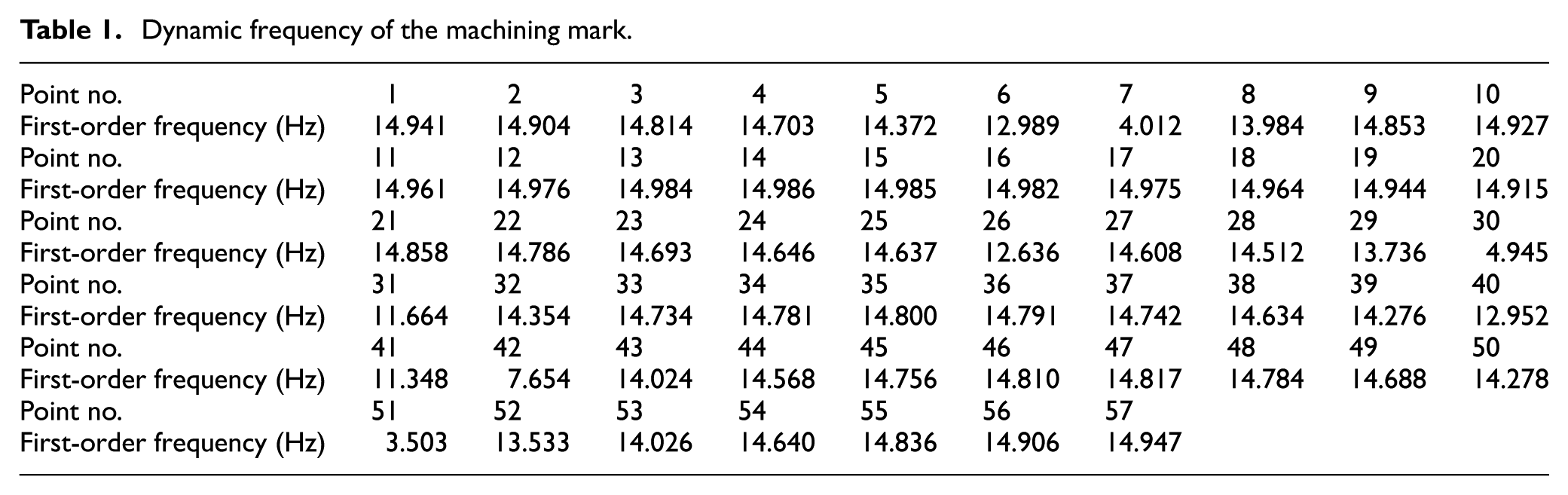
First-order frequency of machining mark on different S part position.
The machining mark is the result of cutting behavior between the workpiece and the tool. The frequency means the number of marks in unit time. For the broken number of frequency, it can be expressed as integer part and remainder part. For example, the first-order frequency at No. 1 point can be known as

where
As said in section “Dynamic stiffness of machine tool on cutting S path,” the actual waviness is co-determined by the continuous marks. The current mark may wipe out the previous profile crest and generate the new one. Both of integer part and the remainder part at these points could affect the surface quality. For example, the frequency of No. 2 point on S part is 14.904. Compared to the frequency of No. 1 point, it represents the same integer part but different remainder part. The phase difference between the two points is very small, so the second mark almost keeps the same profile as the first one. In the same way, the frequency of No. 3 point has the same integer part but a slightly different remainder part. Therefore, in this location, the S part surface shows a good consistency. However, for the sudden change of frequency, the surface quality may be worst, especially for the lower frequency, such as at points 7, 30, 42, and 51 with the larger space of marks. Figure 9 shows the mechanism of surface forming at similar frequency of points or different frequency of points.

Mechanism of surface forming.
Experiment validation on S part
Spacing observation on microscope
Figure 10 shows an S part processed by machine tool V51030ABJ with AB rotary axes. The cutting parameters are listed in Table 2. After completion, the S part surface is cleaned and measured by the coordinate measurement machine (CMM).

Machining process of the S part.
Cutting parameter table.
A microscope device is used with 500 times magnification to observe the micro-surface, as shown in Figure 11. In the microscopic observation, there are two obvious periodic cutting marks in large spacing and small spacing. In microscope measuring, the smaller spacing is 0.25 mm and the large one is 1.5 mm. According to the vibration frequency of milling, the integer of primary frequency is 15 Hz. Thus, the theoretical small spacing of each teeth is 20/(50*2) = 0.2 mm and the large spacing on each cycle (frequency) is 20/15 = 1.33 mm. All the results are listed in Table 3. The theoretical calculations are slightly less than the experimental measurements. The reason for this may be that the spindle speed fluctuates during the process. So, the theoretical calculation is less than the measured value. However, the results have shown that the primary vibration frequency mainly affects the surface formation.

Surface micro-display of the S part.
Comparison of the analysis and measured results.

Surface measurement
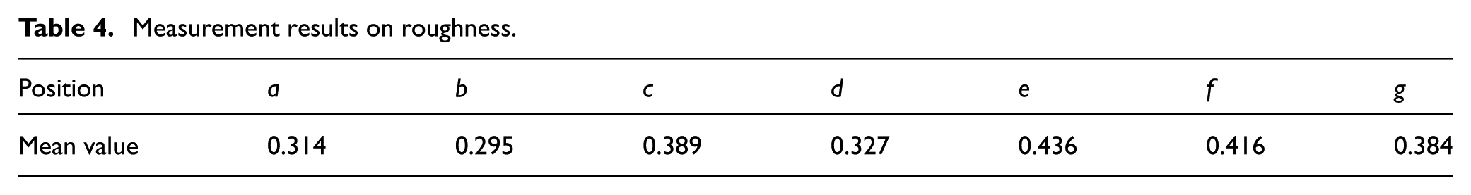
Two spacings of waveforms in surface indicate using different index to evaluate the surface quality. Surface roughness and surface waviness commonly characterize the surface micro-geometry. The machined S part is measured by Taylor instrument, which can give both roughness and waviness on same area. For the probe that cannot touch the whole surface, seven positions are selected based on the distribution of frequency and surface quality observation, as shown in Figure 12, to check the analysis results.
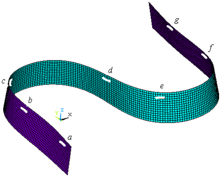
Measurement position on S part.
Roughness results are listed in Table 4. All of measuring values are less than
Measurement results on roughness.
The recommended measuring conditions for waviness in the International Organization for Standardization (ISO) 19 are listed in Table 5. Each condition includes different high-pass filters, sampling lengths, and evaluation lengths. To evaluate the accuracy of results, the measurement uncertainties are given on each condition.
Waviness measuring conditions.

The pictures of S part at position a, b, and d are shown in Figure 13. Position a is the ideal surface with lower waviness value and normal frequency in area nearby. Position b has the largest waviness with obvious chatter marks, which is the worst case on milling surface and should be avoided in first place. In the area of lower primary frequency, position d also has poor surface quality. Due to the less dynamic stiffness of processing, position d has surface defects. The waviness value also increases at this position. Compared with the surface quality at ideal area, the chatter and lower primary frequency, the waviness measurement can represent the feature of surface quality.

Comparison of surface quality at different position: (a) surface at position a, (b) surface at position b, and (c) surface at position d.
Control method on surface quality
Equation (14) describes the relationship between the processing parameters and the frequency of mark. The solution of primary frequency is mainly affected by the square item, that is

Substituting equation (15) into equation (39), the first-order frequency is known as

Equation (40) shows that the equivalent mass, dynamic stiffness, damping, spindle speed, and overlap coefficient all have an influence on the solution. The relationship between primary frequency and the influenced factor is plotted in Figure 14. Usually, the first-order frequency increases with damping, overlap coefficient, spindle speed, and stiffness. Therefore, the surface quality can be improved by adjusting process parameters. The changed parameters should be carefully selected and calculated in some special position. Figure 15 shows the simulation of primary frequency by changing the feed rate at potion b, c, d, and f (see Figure 12). Obviously, the new distribution of frequency has the similar frequency, which easily achieves the better surface quality. In other case, considering the motion of five axes has the effect on dynamic stiffness, optimization of the machining path, in other words, changing the position or orientation of each axis is another choice for improving the surface quality.

Influence of the process parameters on the first-order frequency: (a) mass and damping to frequency, (b) damping and overlap cofficient to frequency, (c) stiffness and overlap cofficinet to frequency, and (d) damping and spindle speed to frequency.

Comparison of frequency distribution: (a) initial frequency distribution and (b) frequency distribution with changed feed rate.
Conclusion
In this article, a new method to present machining quality of sculptured surface is proposed. The formation mechanism is explained during intermittent milling process. The proposed model can be used to calculate the frequency of cutting behavior. The actual surface quality depends on the distribution of cutting frequency. Poor surface quality possibly appears at lower frequency or jumping one.
A sculptured surface, S part, is illustrated as a case study. The map of dynamic stiffness and the first-order frequency in the process is calculated. Measured by instruments, the waviness of surface more reflects the fluctuation of surface quality. The locations at lower frequency have obvious surface defects with larger waviness value. Besides to predict the quality, the proposed method can also use to adjust the surface quality by changing the process parameters. The equivalent mass, dynamic stiffness, damping, spindle speed, and overlap coefficient all have an influence on the primary frequency. Such method helps the supplier or the user to better understand the performance limit of machine center on cutting sculptured surface.
Footnotes
Academic Editor: Yaguo Lei
Declaration of conflicting interests
The author(s) declared no potential conflicts of interest with respect to the research, authorship, and/or publication of this article.
Funding
The author(s) disclosed receipt of the following financial support for the research, authorship, and/or publication of this article: This paper was funded by the National Natural Science Foundation of China (51205048, U1530130) and the Fundamental Research Funds for the Central Universities.