
Abstract
Phenomenon of concealed cracks is one of the familiar failures in the road base. Accurate concealed crack localization of the road base using ground penetrating radar still suffers from some limitations. To accurately locate the concealed cracks in the road base, an effective concealed crack localization method based on ground penetrating radar is proposed in this article: first, continuous ground penetrating radar scanning and manual point-by-point detection are performed to determine the location of the concealed crack roughly; then the ground penetrating radar–based ellipse method and an improved data processor based on MATLAB are used for processing the data to determine the accurate location of the concealed crack. The proposed method is experimentally validated using a rectangle concrete block with a concealed crack, and the results of the proposed method are compared with that of the previous method. All results indicate that the proposed method can be used to locate concealed cracks fast and well; moreover, the localization accuracy of the proposed method is obviously higher than the previous method; all these lay a good foundation for engineering applications.
Introduction
The base is an essential part of the road that directly contributes to supporting the pavement and transmitting its loads directly to the earth. Failures usually happen in the road base during service period, which seriously affect the health and service life of the road. Failure detection has become an important mission in road engineering during recent years. 1 Phenomenon of concealed cracks is one of the familiar failures in the road base; it may lead to base crush, base settlement, and surface cracking in the road. These damages are always irreversible and the cost of appropriate repairs is very high; even more serious is that they have harmful consequences such as significant risks for drivers.2,3 Accurate and non-destructive localization of concealed cracks is of great importance for engineering decisions related to road maintenance and rehabilitation programs.
A great deal of research has been undertaken in crack detection for roads.4–6 By far, there is no standard crack detection method. Digital images7,8 have been widely applied to crack detection for a long time: surface cracks of the pavement could be identified correctly and automatically after further processing of the image.9,10 In the last few decades, various methods based on image-processing approaches have been proposed for crack detection with the advance of the high-speed camera technology and the large-storage hardware. 11 But when it comes to the concealed crack, which is hidden under the road surface, digital images and manual detection are helpless.
Ground penetrating radar (GPR) has been modernly used in engineering since a few decades ago. 12 Civil engineering applications of GPR include condition assessment of highway pavements and their foundations, crack monitoring in buildings, 13 evaluation of structural deformation, 14 inspection of bridge 15 and so on. GPR has become a powerful tool of the crack detection for roads and is widely used in recent years because of its characteristics such as quick speed and non-destruction. Diamanti and Redman 5 studied the potential of GPR for detecting and characterizing vertical pavement cracks based on field observation and numerical modeling finite difference time-domain (FDTD) method, 16 finding that high-frequency GPR is more appropriate for crack characterization and low-frequency GPR is more effective at detecting cracks. Jeng and Chen 17 performed a GPR survey in a potential collapse urban area utilizing a new data processing scheme, and successfully imaged the top pavement layers, voids, and utilities within about 2 m depth. The efficiency and quality of the results are demonstrated by a comparison with those of the direct excavations. The detected subsurface voids could provide a prediction for the potential collapse in the study area of roads and also a good guidance for road maintenance and rehabilitation programs. Lu et al. 18 proposed a practical method for detection of concealed cracks in the road base using GPR. The horizontal positions, depths, and relative widths of the concealed vertical cracks in horizontally layered homogeneous mediums within about 2 m depth can be determined clearly based on the method. Moreover, to ensure the accuracy of the detection, appropriate-frequency GPR should be adopted, and the distances between the adjacent detection points should be smaller than a third the distance between the sending antenna and the receiving antenna of GPR. This research lays a good foundation for accurate concealed crack localization of the road base.
These previous studies have demonstrated that GPR is maturely applied in crack detection of the road base. But few studies about accurate concealed crack localization of the road base based on GPR have been found. Rapid detection can only roughly locate concealed cracks, but when it comes to the small cracks, the rough localization sometimes cannot meet the requirements of the road quality assessment and maintenance. To improve the localization accuracy, Lu et al. 18 indicate that the distance between two adjacent detection points should be small enough. What is more, both the thickness of the road base and the depth of a crack are varied; thus, the appropriate choice of the radar frequency is also important for the localization accuracy. 18 There is a growing interest in accurate concealed crack localization. This article focuses on the localization of vertical concealed cracks and near-vertical concealed cracks in the road base. Generally, experimental verification is necessary for a new detection method.19–22 In addition, large amounts of GPR data will be produced in the accurate concealed crack localization, and a fast data processing approach is necessary for dealing with massive amount of data.
In this article, a concealed crack localization method based on GPR is proposed. The theory of the method is validated utilizing a mathematical model, and the data analysis of the model is programmed using MATLAB. The feasibility and validity of the method are examined by an experiment using a rectangle concrete block with a concealed crack, and the results of the proposed method are compared with those of the previous method. The results indicate that the proposed method has good accuracy.
Proposed concealed crack localization method based on GPR
A concealed crack localization method for the road base using GPR is proposed. In this section, the theory and procedure for the proposed concealed crack localization method are detailed.
Working principle of GPR
Propagation character of the electromagnetic wave
GPR is a kind of device that makes use of the propagation and reflection features of the pulse electromagnetic wave in the underground medium for detection and localization. It is mainly composed of a transmitting antenna, a receiving antenna, and a computer processing system. When GPR works, the electromagnetic pulse is emitted from the transmitting antenna to the ground. After propagating and reflecting in the underground mediums, the electromagnetic pulse is received by the receiving antenna. Then the data of the reflected wave are transferred to a computer processing system, and finally, images that reflect the propagation characteristic of the electromagnetic wave are obtained.
Electromagnetic wave can be reflected and refracted at the interface of two different mediums. Figure 1 shows the propagation path of the electromagnetic wave in two contiguous mediums. θ1, θ2, and θ3 are the angle of incidence, the angle of reflection, and the angle of refraction for the electromagnetic wave, respectively; v1 is the velocity of the incident wave and reflected wave; v2 is the velocity of the refraction wave; ε1 and ε2 are the permittivity of the two mediums, respectively; and R12 is the reflection coefficient of the electromagnetic wave between the two mediums. R12 is defined as follows

where E1 and E2 are the electric field intensities of the incident wave and the reflected wave, respectively.
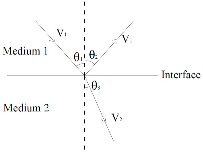
Propagation path of the electromagnetic wave in contiguous mediums.
The transmitting antenna and the receiving antenna of GPR are very close, and the electromagnetic wave is approximately vertical incidence. Thus, the angle of incidence can be approximately considered as 0. Therefore, R12 can be approximately defined as follows
The relationship between the reflection coefficient of the two mediums and reflection amplitudes of the electromagnetic wave in the two mediums is shown as follows

where A1 and A2 are the amplitudes of the electromagnetic wave in the two mediums, respectively.
The dielectric constant of air is 1, and the dielectric constant of the base material of the highway is times bigger than 1. Electromagnetic wave can be reflected at the interface between the concealed crack and the road base. Thus, the amplitude and phase of the electromagnetic wave change at the surface of the concealed crack and these changes can be identified by GPR.
Crack detection
The electromagnetic wave is emitted from the transmitting antenna, and then it is reflected at the interface between the concealed crack and the road base, finally it is received by the receiving antenna. The propagation path of the electromagnetic wave for target detection based on GPR is shown in Figure 2. s1 and s2 are the lengths of the incident path and reflected path of the electromagnetic wave, respectively; t1 and t2 are the times of the incident path and reflected path of the electromagnetic wave, respectively; h is the burial depth of the underground target; d is the distance between the transmitting antenna and the receiving antenna of GPR; and x is the horizontal distance from the concealed crack to the midpoint of the two antennas.
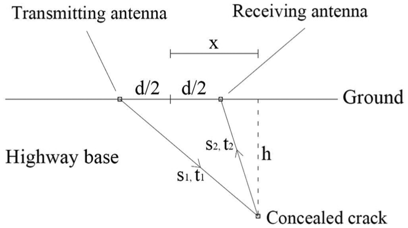
Propagation path of the electromagnetic wave in the road base.
Based on the principles of geometry, t1 and t2 can be defined as follows

where v is the velocity of the electromagnetic wave in the road base. The total length of the incident path and the reflected path of the electromagnetic wave is defined as

Ignoring the distance d between the transmitting antenna and the receiving antenna, the propagation time t can be defined as follows

Equation (6) can be conversed as a standard hyperbolic equation

Thus, the propagation time shows a hyperbolic waveform in the detection of the concealed crack. In addition, the value of t reaches the minimum when x is 0, that is, the whole propagation time of the electromagnetic wave in the transmitting and receiving process reaches the minimum value when the concealed crack is located under the midpoint between the sending antenna and the receiving antenna. Figure 3 shows the GPR image of propagation time for the detection of the concealed crack. A half-hyperbolic waveform is obviously shown in it, and the vertex of the half-hyperbola curve presents the minimum value of t. In this way, the horizontal position of the concealed crack can be roughly determined based on general detection using GPR.

The GPR image of propagation time for a detection of concealed crack.
The concealed crack localization method
Mathematical model
According to Figure 2, the concealed crack is located on an ellipse whose foci are at the two antennas of GPR and the length of the major axis equals that of the whole propagation path of the electromagnetic wave. The ellipse can be defined as follows

GPR and its antennas change their positions during detecting; thus, many ellipses correspond to different locations of the antennas. Therefore, the position of the concealed crack can be determined by the common intersections between these ellipses, as shown in Figure 4.
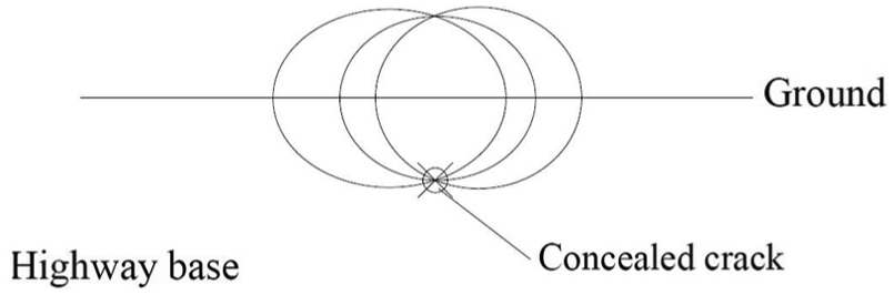
Ellipse corresponding to different locations of the antennas.
Detection procedure
In the detection process, first, a continuous detection is conducted to determine the rough position of the concealed crack using GPR. Then a “discrete” detection is conducted to determine the accurate position of the concealed crack based on the “elliptic model” in the last section. A string of positions near the rough position of the concealed crack are selected for the detection points of the discrete detection. When discrete detecting is conducted, the midpoint of the two GPR antennas is set at the detection points, as shown in Figure 5.

Detection points for “discrete” detection.
The total length of the incident path and the reflected path of the electromagnetic wave corresponding to each detection point is obtained by the following equation

Several detection points, of which the corresponding propagation path is the smallest in the detection points for discrete detection, are selected to determine the accurate position of the concealed crack. There are two reasons to select these detection points. At first, these selected detection points are the nearest detection points to the concealed crack so that the electromagnetic wave losses in the corresponding propagation paths are relatively small. On the other hand, these detection points are on both the sides of the concealed crack in theory; thus, the detection error can be reduced to some degree because of the symmetry of the hyperbola. The corresponding ellipses of these detection points can be determined by equation (8). In theory, the position of the concealed crack can be determined by the common intersection between these ellipses, but the ellipses usually have no common intersection due to the detection error. Therefore, the average coordinate values of the intersections can be adopted to determine the position of the concealed crack. To ensure accuracy of the result, appropriate ellipses should be selected through further analysis.
On one hand, the number of ellipses is directly proportional to the accuracy of the result in theory. In other words, a low number of ellipses lead to a low accuracy result. On the other hand, a large number of ellipses lead to a large amount of calculation. To sum up, the number of ellipses is set as three or four. In theory, the final number of ellipses could be determined based on the relative positions of the detection points to the concealed crack. In consideration of the symmetry of the hyperbola, three ellipses near the concealed crack would be selected if a detection point is close to the concealed crack (Figure 6(a)), and four ellipses near the concealed crack would be selected if the midpoint of two detection points is close to the concealed crack (Figure 6(b)). In this way, the detection error can be reduced to some degree based on the symmetry of the hyperbola.
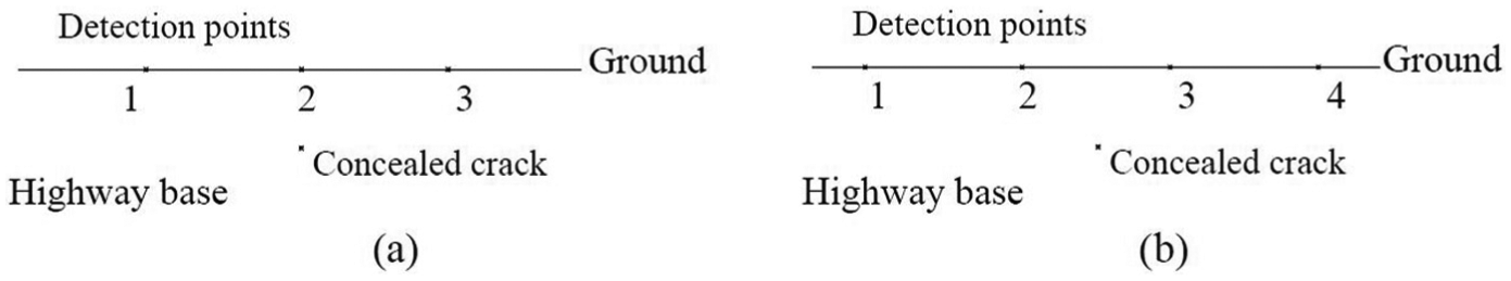
The relative position between the concealed crack and the detection points.
The relative position between the concealed crack and the detection points is unknown after discrete detection, but the number of the ellipses can be determined by analysis for the positions of the intersections between the ellipses, which will be introduced based on the experiment in this article.
Data processor
There can be large volumes of data to be processed based on the proposed method in this article, and processing the data manually costs much time. To address this issue, a combination of MATLAB and IDSP 5.0 is used for post-processing of data. With this combination of software, crack location can be determined quickly. The program flow chart of MATLAB is shown in Figure 7, which reveals the framework of the developed code. In Figure 7, the algorithm for the third step (select four detection points and draw the corresponding ellipses) of the program is explained in section “The concealed crack localization method,” while the algorithms for the fourth step (analyze the coordinates of the ellipses’ intersections and determine the best detection points) and the fifth step (get the coordinates of the concealed crack) of the program are explained in section “Experimental results” in this article.
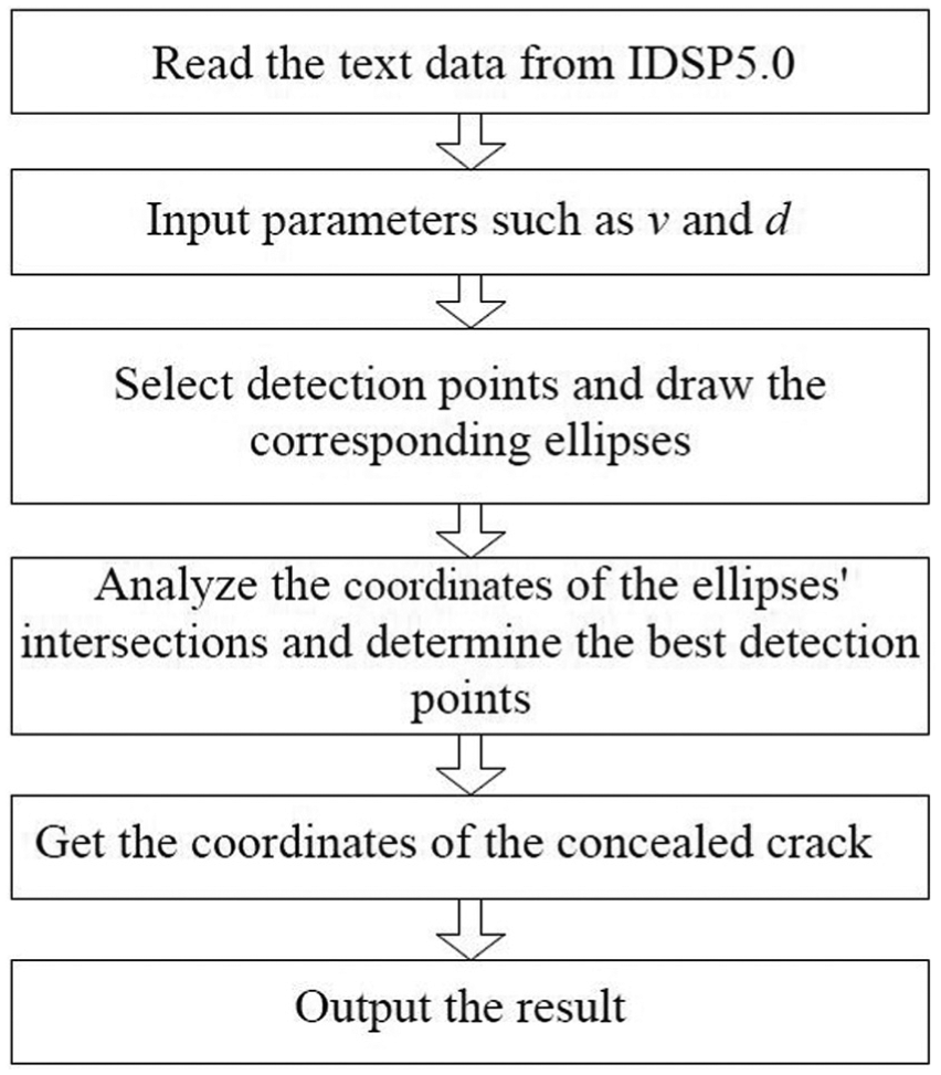
The program flow chart of MATLAB.
Experiment
To verify the feasibility and validity of the proposed method, an experiment using a rectangle concrete block with a concealed crack is conducted to locate the concealed crack. The concealed crack location obtained based on the proposed method is compared with that obtained based on the previous method, and both the results of the two methods are compared with the real concealed crack location.
The experimental setup
The experimental model is formed by two concrete blocks whose dimensions are 100 cm × 10 cm × 7.3 cm and 100 cm × 10 cm × 5.8 cm, respectively. The mixture ratio of cement, sand, stone, and water for the concrete is 240:894:1026:135. The grade of cement is C15. The concrete block with a thickness of 7.3 cm is disconnected in the middle to simulate the concealed crack, and the concrete block with a thickness of 5.8 cm is placed on the disconnected one to simulate the surface level. The width of the crack is quite small and it is 5.8 cm deep under the “ground” (Figure 8). The GPR model is LTD-2000. A 900-MHz coupling antenna is equipped on the bottom of GPR. The length and height of the antenna are 33 and 9.5 cm, respectively. The distance between the transmitting antenna and the receiving antenna is 5 cm. And the time window is set to 15 ns.

Experimental model.
Measurement for permittivity of the concrete
An inversion method is adopted to measure the permittivity of the concrete based on GPR. The concrete block with a thickness of 7.3 cm is adopted. Figure 9 shows the theory of the measurement. H is the thickness of the concrete block; v is the velocity of the electromagnetic wave in the concrete.

Theory of the measurement.
At first, the thickness of the concrete block is measured by GPR with an assumed velocity v′ (0.1 m/ns) of the electromagnetic wave set in GPR. The thickness of the concrete block H can be defined as follows based on the principles of geometry

The velocity of the electromagnetic wave in the medium is

where c is the velocity of the electromagnetic wave in vacuo. According to formula (11) and formula (10), the permittivity of the medium can be obtained as follows
To ensure the accuracy of the result, the measurement is conducted 20 times. Figure 10 shows the measured thicknesses obtained by the measurement using GPR, and the average value of the 20 measured thicknesses is 7.6 cm.

Measured thicknesses obtained by the measurement.
The actual permittivity of the concrete can be calculated by the following formula
The real permittivity of the concrete of the concrete specimens is 9.8, and the corresponding velocity of the electromagnetic wave in the concrete is 0.096 m/ns.
Experimental results
A continuous detection is conducted to determine the rough position of the concealed crack in the concrete block using GPR at first. Then a string of positions near the rough position of the concealed crack is selected for the detection points of the discrete detection; these points are marked by a string of short lines (Figure 11). The distance between two adjacent detection points for the discrete detection is 1.5 cm. The radargram for the detection of the concealed crack is shown in Figure 12. A plane coordinate system is established for further analysis, with one end detection point taken as the origin, the horizontal line on the top surface of the concrete block taken as the abscissa axis, and the vertical line taken as the longitudinal axis. The coordinates of the concealed crack’s vertex in this coordinate system are (18.0 cm, 5.8 cm).

Photograph of experiment.
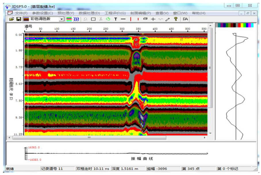
The radargram for the detection of the concealed crack.
The length of the propagation path of the electromagnetic wave for each detection point is obtained and compared by the data processor. Based on the previous method, the detection point whose corresponding lengths of the propagation path of the electromagnetic wave are the shortest in all the detection points can be taken alone to determine the position of the concealed crack: taking the horizontal coordinate of the detection point as the horizontal coordinate for the vertex of the concealed crack and taking the half length of the propagation path of the electromagnetic wave for the detection point as the vertical coordinate for the vertex of the concealed crack. The results of the previous method are compared with the real position of the vertex of the concealed crack (Table 1).
Comparison between the results of the previous method and the real position of the concealed crack’s vertex.

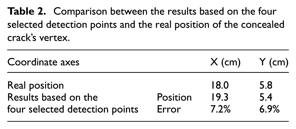
Four detection points whose corresponding lengths of the propagation path of the electromagnetic wave are the shortest in all the detection points are preliminary selected for further analysis. Figure 13 shows the four ellipses corresponding to the four selected detection points in the established plane coordinate system. As shown in Figure 13, six intersections between the ellipses are under the horizontal axis. The average coordinates of these intersections are taken as the coordinates for the vertex of the concealed crack, and these results are compared with the real position of the vertex of the concealed crack (Table 2). The vertical coordinate of the intersection 6 shows obvious differences from the other five intersections, and the positions of the six intersections do not present an approximate symmetry in Figure 13. This could cause errors to the result. Thus, this condition is not the reasonable choice.
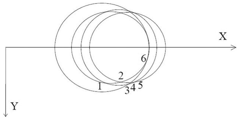
The four ellipses corresponding to the four selected detection points.
Comparison between the results based on the four selected detection points and the real position of the concealed crack’s vertex.
Finally, three adjacent detection points are picked out from the four detection points for more accurate results. Figure 14 shows the three ellipses corresponding to the three selected detection points in the established plane coordinate system. Three intersections between the ellipses are under the horizontal axis, and the positions of the three intersections present an approximate symmetry. The average coordinates of these intersections are taken as the coordinates of the vertex of the concealed crack, and these detection results are compared with the real position of the vertex of the concealed crack (Table 3). The detection results are highly close to the real position of the concealed crack. The errors of the results are obviously smaller than those based on the four selected detection points. In addition, the localization accuracy of the proposed method is obviously higher than the previous method.

The three ellipses corresponding to the three selected detection points.
Comparison between the detection results based on the proposed method and the real position of the concealed crack’s vertex.

Three or four detection points are selected to determine the location of a concealed crack in the proposed method, while only one detection point is selected to determine the location of a concealed crack in this method. In theory, large number of detection points can reduce measurement errors, that is, the number of detection points is directly proportional to the accuracy of the result. Thus, the localization accuracy of the proposed method is higher than the present methods.
Discussion
The data of the previous method are processed based on manual analysis, while the data of the proposed method are processed by the data processor; thus, the detection time using the proposed method is much shorter than those of the previous method. What is more, the localization accuracy largely depends on the distance between two adjacent detection points for the discrete detection, and the localization accuracy is lower than the proposed method.
The detection resolution using the proposed method is affected by some factors. The depth resolution depends on the pulse width (or the bandwidth) of the transmitted signal of the radar. The smaller the pulse width, the higher the depth resolution. The lateral resolution depends on antenna beam width (for a real aperture system) or on synthetic aperture processing. The smaller the antenna beam width, the higher the lateral resolution. And the adoption of a synthetic aperture radar can greatly improve the lateral resolution.
Considering the great difficulty of the detection for concealed cracks in the road base, this article is mainly focused on the localization of the concealed cracks. The proposed method in this article can be used for accurate localization of concealed cracks with various common shapes in the road base. The shape and narrow are all decisive factors of the feature size of a crack. According to our research, the minimum feature size of a concealed crack has significant influence on the detection results. Taking the GPR with a 900-MHz coupling antenna for instance, a concealed crack with a minimum feature size in the range of 1–3 cm can be detected and accurately located using the proposed method; if the minimum feature size of a concealed crack is smaller than 1 cm, the reflection intensity for the crack is too weak to generate an apparent reflection pattern in the radargram; thus, the crack is hard to be detected; if the minimum feature size of a concealed crack is larger than 3 cm, the concealed crack can be considered as a large crack or a void which can be detected and located easily using the previous method.
It is worth mentioning that the radar frequency has significant impact on the depth of a concealed crack that the proposed method can detect. Taking the GPR with a 900-MHz coupling antenna for instance, only the concealed cracks within about 0.5 m depth can be detected using the GPR in this article. Therefore, a GPR with an appropriate frequency is necessary for the detection of the concealed cracks.
The proposed method is a local damage localization method, and it is difficult to be used for a long highway road; it is suitable for the crack detection in a local area of the highway road. The major disadvantage of the proposed method is that it is rather time-consuming for crack localization. Taking a road with an area of 100 m × 12 m for example, first, perform continuous GPR scanning to determine the rough areas where concealed cracks are located; then perform manual point-by-point detection in the selected areas where cracks are located; finally, use the data processor based on MATLAB to determine the accurate locations of the concealed cracks. Detecting such a road may cost about an hour if only one GPR is used. Further study will be necessary for reducing the time of detection. For example, acoustic emission (AE) technique 23 may be used to roughly determine the areas where concealed cracks are located, and then the proposed method in this article can be used to accurately locate the concealed cracks in the road base.
Conclusion
At present, accurate concealed crack localization of the road base using GPR still suffers from some limitations. To accurately locate the concealed cracks in the road base, an effective concealed crack localization method based on GPR is proposed in this article: first, continuous GPR scanning and manual point-by-point detection are performed to determine the location of the concealed crack roughly; then the GPR-based ellipse method and an improved data processor based on MATLAB are used for processing the data to determine the accurate location of the concealed crack. The ellipse method is validated utilizing a mathematical model. The large volumes of data can be processed fast based on the GPR-based ellipse method and the improved data processor. The feasibility and validity of the method are examined by an experiment using a rectangle concrete block with a concealed crack, and the results of the proposed method are compared with those of the previous method. All results indicate that the proposed method can be used to locate concealed cracks fast and well; moreover, the localization accuracy of the proposed method is obviously higher than the previous method; all these lay a good foundation for engineering applications.
Footnotes
Academic Editor: Eleni Chatzi
Declaration of conflicting interests
The author(s) declared no potential conflicts of interest with respect to the research, authorship, and/or publication of this article.
Funding
The author(s) disclosed receipt of the following financial support for the research, authorship, and/or publication of this article: The authors are grateful for the financial support from the National Natural Science Foundation of China (51208471), Outstanding Young Talent Research Fund of Zhengzhou University (1421322059), the Science and Technology Planning Project of Transportation in Henan Province (2016Y2-2), and the Specialized Research Foundation for the Doctoral Program of Higher Education (20114101120008).