
Abstract
This article develops a systematic model to study electric vehicle powertrain system efficiency by combining a detailed model of two-speed dual-clutch transmission system efficiency losses with an electric vehicle powertrain system model. In this model, the design factors including selection of the electric machine, gear ratios’ change, multi-plate wet clutch design, and gear shift schedule design are considered. Meanwhile, the application of detailed model for drag torque losses in the gearbox is discussed. Furthermore, the proposed model, developed with the MATLAB/Simulink platform, is applied to optimize/maximize the efficiency of the electric vehicle powertrain system using genetic algorithms. The optimization results demonstrate that the optimal results are different between simulations via New Europe Drive Cycle and Urban Dynamometer Driving Schedule, and comprehensive design and optimization of the powertrain system are necessary.
Keywords
Introduction
With the dramatic increase in oil consumption, the finite amount of fossil fuel resources is risking our future development on the planet. It is known that the largest energy sector is the transportation sector, which has the highest growth rate in terms of oil consumption. Meanwhile, transportation emission closely corresponds to several environmental issues, 1 such as the greenhouse effect, acid deposition, and air pollution. Among the increasing demands on transportation, growth has largely come from the growing needs of personal use vehicles equipped with combustion engine. These issues attract concern from more and more governments and organizations that have developed tougher standards for fuel consumption and emissions. It is widely accepted that one of the major directions to relieve or resolve related energy and environmental issues is to develop alternative powertrain technologies, for instance, plug-in hybrid electric vehicles (PHEVs) and fuel cell vehicles (FCVs) could be used in the short-term to mid-term, and EVs could be used in the long-term.2–6
Recently, an increasing number of researchers have been paying attention to the development of PHEV and EV to reduce fossil fuel consumption and improve vehicle powertrain system efficiencies. So far, various methods can be applied in relation to modeling and optimizing pure EVs, such as powertrain system component design,4,7 topology analysis,8–10 batteries, energy management strategies and analysis,2,6,11–15 application of super-capacitor, 16 and drive control17–20 of EVs. However, there are only a limited number of available reports on the application of multi-speed transmission to EVs. In the current market, the popular used pure EVs, such as the configurations shown in Kamachi et al., 21 Tesla Motors, 22 and Salisa et al., 23 which are generally installed with single-speed (constant gear ratio) transmission or installed with double e-motors, with tradeoffs among dynamic and economic performance (driving range), and manufacture cost.
The application of the multi-speed gearbox to EV is a technique to increase the average e-motor efficiency and drive range capacity, or to even reduce the demanded e-motor size. It is important to note that due to the significant different characteristics of the EV and the engine-driven vehicle, they have pronounced different vehicle performances using multi-gear transmissions. 19 Compared with the engine-driven system, the electric motor has a broader available output speed range of engine, smaller inertia (smaller than a quarter of internal combustion engine (ICE)), and a more controllable speed. It should be said that the number of speeds (gear ratios) for a general EV are not “the more the better,” as these will increase the vehicle mass and manufacture fees without contributing significantly to the overall economic and dynamic performance of the vehicle. Other detailed difference comparisons between EV equipped with single-speed and two-speed transmissions can be found in our previous research work.24,25
It is noted that under a given demand power and vehicle speed, the instantaneous motor torque is directly influenced by the transmission gear ratio selection and shifting schedule. Hence, there are some researches on EVs’ gear shift schedule design and optimization, such as Floyd 26 and Zhu et al. 27 Some researches such as Sorniotti et al. 28 and Zhou et al. 29 consider the multi-speed EV powertrain optimization as a function of the electric motor properties. However, these references only focus on gear shift schedule optimization with given gear ratios without considering the best use of gear ratios to maximize electric motor efficiency. As a result, there is still a lack of publications which combine the gear shifting schedule, gear ratios’ optimization, and clutch design to improve overall EV performance.
In fact, the drivetrain systems’ efficiency is directly affected by both the transmission gear shift schedule and the transmission gear ratios’ election. 30 For a motor, the shift schedule and transmission gear ratio pair selection are closely linked and mutually affected. 24 Thus, to improve the performance of EV, it is necessary to optimize the gear shifting schedule and gear ratios’ selection together, to enable the motor to operate in higher efficiency zones.
This article is organized as follows. The configuration of the two-speed EV powertrain system will be presented and modeled in the “EV powertrain system modeling” section, as well as electric motor selection, gear ratios’ design, shift schedule discussion, multi-plate wet clutch plates’ design, and drag torque model application. In the “Optimization via GAs” section, a genetic algorithm (GA) method is applied to the design, and optimal processes are used to accelerate the computational process. Then, the simulation results and analysis are presented in the “Results and analysis” section. Finally, this article is summarized in the “Conclusion” section.
EV powertrain system modeling
Layout of EV powertrain system
The pure EV powertrain system under considerations, as shown in Figure 1, is equipped with a dual-clutch transmission (DCT) with only two speeds. Aluminum alloy is used to make this two-speed DCT housing. The clutch pack of DCT includes two multi-plate wet clutches, inner clutch (C1) and outer clutch (C2). C1 and C2 have a common drum, which is attached to the same input shaft from the e-motor. The clutches’ friction plates are independently connected to the first and second gears, that is, C1, as shown in green within Figure 1, connects the outer input shaft engaged to the first gear, and C2, as shown in red within Figure 1, connects the inner input shaft and the second gear.
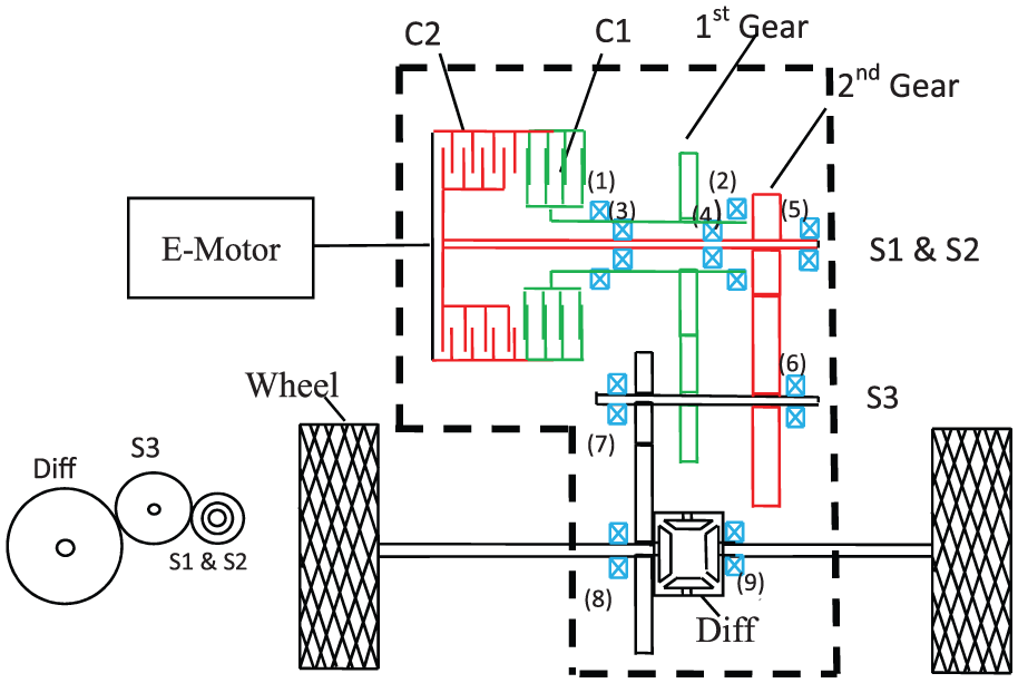
Schematic of EV powertrain system equipped with a two-speed DCT.
Unlike our previous researched two-speed DCT, which is modified from a six-speed double-clutch transmission, the two-speed DCT under consideration is modified a little. After analysis of the drag torque losses in the original two-speed DCT, 29 we find that we can diminish the drag torque loss and improve the reliability by redesigning the two-speed transmission. The two clutches’ plates’ radii are designed to be the same to diminish the disengaged clutch drag torque losses. Within the two-speed DCT, no synchronizers are equipped; hence, the control system can be simpler and the manufacturing cost can be reduced. In fact, the transmission can be considered as two clutched gear pairs. Therefore, in this way, gear shifting can be performed via simultaneous shifting between two halves of the gearbox.
Modeling of the EV powertrain system
The general model of the pure EV powertrain system is based on Simulink within MATLAB, using a bottom–up modeling strategy, which can be found in our previous work. 24 Table 1 lists the vehicle parameters for a larger passenger sedan. The design elements to be studied in this article for the two-speed EV powertrain system main include selection of electric machine, gear ratios’ boundary, multi-plate wet clutch design, gear shift schedule design, and also the detail power losses in the gearbox.
Vehicle parameters.

E-motors
There are enormous types of e-motors in the industry to drive various kinds of machines. In terms of the EV, some performance indexes of EV should be considered when selecting electric motors, such as efficiency, weight, cost, top speed, and maximum output torque. 31 To meet the requirements shown in Table 2, five motors are selected under consideration in this research, as shown in Table 3. Mn1, Mn2, and Mn3 are all brushless permanent-magnet continuous motors, while Mn4 and Mn5 are alternating-current motors. Efficiency maps of the five motors are shown in Figure 2. The study of drive tracks in motor efficiency maps for two-speed EV can be referred to in our previous work. 29
Vehicle performance requirements.

E-motors’ parameters.

DC: direct current; AC: alternating current.

Efficiency maps of five motors from Mn1 to Mn5.
Gear ratios’ boundary
The goal of optimization of vehicle transmissions is to supply the vehicle with maximum driving performance. When a multi-speed EV is considered, minimization of losses becomes critical to the development of the drivetrain, ensuring that the benefits of the integrated transmission and electric machine are maximized. Through this analysis, a methodology is put forward for determining the optimal gear ratios for the powertrain when consideration of losses in the wet clutch is taken into account. In the following sections, gear ratio bounds and selection are introduced and discussed, as shown in Figure 9, and the design of the associated shift schedule is also introduced for integration with the drivetrain efficiency analysis.
As concluded by Eshani et al., 19 the vehicle transmission has to provide ratios between the engine or e-motor speed and the automobile wheel speed so as to enable the vehicle to
Move under difficult conditions.
Reach the required maximum speed.
Operate in the fuel-efficient ranges of the engine/motor performance map.
Therefore, it is necessary to bound permissible transmission ratios meeting the requirements above. The maximum gear ratio required
For an EV equipped with two-speed transmission, the first gear ratio is mainly used to meet the dynamic performances, such as acceleration and grade ability. And the second gear ratio is mainly used to enable the EM operating in high-efficiency zone with high economic performance. This enables it to reach the top speed requirements.
At low speed, the minimum value of first gear ratio

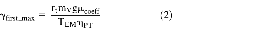
Additionally, the maximum first gear ratio can be evaluated from the maximum ground track force
Contradicting this requirement is the top speed achieved by the vehicle. The lowest gear ratio can be defined by dividing a desired maximum vehicle speed into the linear equivalent of the maximum motor speed
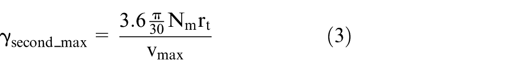
To confirm that the motor can provide the required torque at this speed, from equation (4), it is assumed that there is no incline load, and the rolling resistance torque is divided by the maximum motor torque

And the minimum ratio of second gear

Additionally, considering the manufacturing effects and the shift quality, the gap between two gear ratios should not be too large. The ratio (first gear min)/(second gear min) = 3.4 is the largest desirable step between the two ratios. If it is too large, the shift will take a long time and have poor quality.
Thus, for any given vehicle characteristics and performance requirements, it is possible to bound the required ratios in the transmission. With the given vehicle and EM parameters, the range of first gear and second gear ratio is bounded, as shown in Table 4.
Bounded gear ratios.

Design of multi-plate clutches
The general function of a vehicle clutch is to enable it to disconnect and connect two static or rotating shafts. In pure EV, the clutch is used to connect the motor and the gearbox. Shaft connection can be realized via a series of techniques, such as mechanical friction, hydraulic type or pneumatic ways, or by their combination. The clutches considered here are of the friction type.
The requirements for designing clutches are listed as follows: 32
The required actuation force should be within a certain range.
The friction coefficient should be reasonably stable and constant.
The heat raised from friction must be dissipated in time.
Wear should be limited to enable it to provide reasonable vehicle clutch life.
The goal can also be looked up to obtain the desired clutch with the maximum maintainable friction coefficient and minimum wear. Proper clutch selection and design and selection are important. If a clutch is too small, slippage and overheating will occur. If a clutch is too large, the clutch itself will have a high inertia and might lead to overloading the drive.
Clutch type and configuration selection are based on the desired application. 33 In this article, multiple disks are chosen to be designed for the pure EV powertrain system, as shown in Figures 1 and 3. Two common assumptions are applied to the development of steps for disk clutch design, that is, uniform rate of wear and uniform pressure distribution assumptions. As the uniform wear assumption employs a lower torque capacity clutch than the uniform pressure assumption, clutches’ designs are widely based on the assumption of uniform wear, as it leads to a lower torque capacity than that which is based on an assumption of uniform pressure.

Schematic of an open wet clutch.
The procedure for obtaining the initial geometry is listed as follows: 32
Determine the required torque capacity. In the pure EV, it can be decided by the maximum output torque of the e-motor
Determine the maximum permissible pressure
Decide the coefficient of friction
Decide the outer radius of the clutch plates
Find the inner radius of the clutch plates surface

The number of clutch plates’ surface number N can be calculated by equation (6)
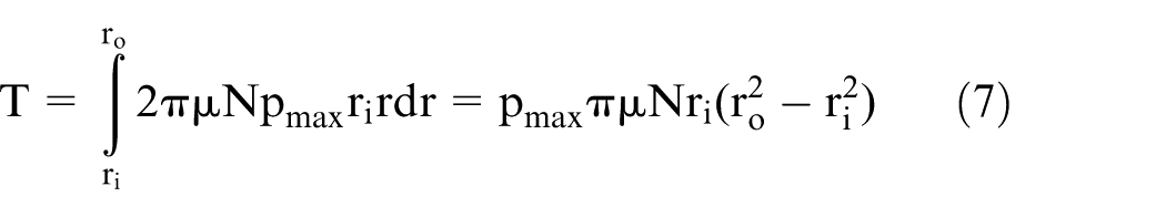
where T is the maximum torque transmitted via a clutch. It is the same as the electric motor maximum output torque
Transmission power loss modeling
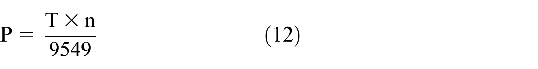
The overall power loss

When clutch 1 (C1) is closed, the vehicle is running with the first gear, while C2 will be in open status and will cause power losses for lubricant viscous shearing


where
For example, concentric shaft–caused power losses can be expressed as
The sum of power losses raised by nine bearings and three gear pairs’ meshing can be achieved from equations (14) and (15), respectively


The gear rotating windage and churning–related power losses are
The power loss raised within the wet clutch package is

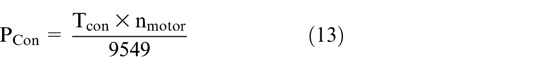
After the previous simulation study, Figure 4 shows the five parts of drag torque losses at different input speeds. It shows that the wet clutch–related drag torque loss is the major loss in this kind of two-speed DCT. The other important sources of power losses are from gear churning and windage losses and bearing-related losses. All of them are affected by the speed, hence indirectly influenced by the gear ratios. Hence, combination consideration of gear ratio design and drag torque is significant. The drag torque model in detail is also covered in our previous research work. 29
Power losses within two-speed DCT engaged with the second gear with input torque of 60 N m.
Shift schedule design
To enable the operation of the electric motor in its higher efficiency region, that is, improve the powertrain efficiency as well, every two-speed transmission model is equipped with a shift schedule, as shown in Figure 5. Two separate lines are presented for up and down shifts. The shift map is both throttle angle– and vehicle speed–dependent. The shift schedule logic for the two-speed transmission is described as follows:
Via the throttle angle and gear shift schedule, two speeds for the up and down shift can be achieved.
Compare the actual vehicle with two shift speeds from (1).
For up shift logic, if the actual vehicle speed is higher than the up shift speed, that is, it passes across the up shift line from zone 2 to zone 3, the second gear will be selected.
Similarly, for the down shift logic, if the actual vehicle speed is lower than the down shift speed, that is, it passes across the down shift line from zone 2 to zone 1, then the first gear will be selected.
For braking events, a similar logic to that described above follows, such that once the motor speed is too low, the higher ratio is selected.
If the vehicle is stopped, the shift map is overridden and the first gear is selected.

Sample of two-speed DCT shift schedule.
Every group of gear ratios is equipped with a different shift schedule. The previous procedures to acquire the shift schedule according to gear ratios can be found in our previous work. 24 In this study, the shift schedules will automatically change according to the variation in gear ratios and the selected e-motor.
Optimization via GAs
It is obvious that it is not possible to reasonably obtain the optimal performance specifications for two-speed EV powertrains through the direct selection and determination of gear ratio, clutch radius, and, consequently, shift schedule. However, it is likely to apply a number of simulation-based methods, such as parametric analysis, to achieve optimal combination of gear ratios, shift schedule, and clutch size for individual configuration. Hence, GAs are applied in this work using model-in-the-loop simulations to acquire optimal specifications for the two-speed transmission equipped powertrain system.
The major merit of GA optimization is that it is not a gradient-based approach, and it requires relatively little information to conduct analysis. The demerits of such methods are that they cost an intense number of computer simulations to obtain the optimal value. Other detailed discussion on GA optimization and its applications can be seen in Chan.3,34 The model-based GA optimization discussed here is an iterative process, as shown in Figure 6.

Genetic algorithm optimization strategy.
A range of possible solutions can be determined from the design and boundary methods mentioned earlier, and it can be later evaluated by applying the model. After the model-in-loop simulation, the results are evaluated against constraints and convergence. If convergence is not reached, a range of better solutions are selected, crossover, mutation, and recombination, to determine a new range of variables within the best variables. Then the two-speed pure EV model is evaluated again to get the new results for the objective function and the constraint functions. This iterative process continues until the objective values converge and final optimal results are attained.
Design variables
In this work, the initial intention of design and optimization is to improve the efficiency fuel economy for pure EV. Hence, the solution is quite apparent, that is, to carry the transmission ratios, shift schedule, drag torque model, and clutch radius into the model-in-loop simulations to acquire the maximum pure EV efficiency.
The bounded gear ratios for the transmissions are shown in Table 4. The range of clutch outer radius and shift schedule are discussed in sections “Design of multi-plate clutches” and “Shift schedule design,” respectively.
Constraints
For any vehicle, drive range and performance are the two key factors that affect the consumer’s acceptance. For the EV, several specifications were defined as minimal goals for achieving an optimal design of the vehicle powertrain system as shown in Table 2, which becomes the constraints.
Additionally, to terminate the simulation when the adjacent optimal results approach equal, a constraint is added. If the number of generations is more than five, and the absolute value between the adjacent optimal results is smaller than 0.01, then the simulation will be terminated. Otherwise, the simulation will continue running.
Objective function
The objective function drives optimization via maximizing the average motor and DCT operating efficiency during running the chosen drive cycles. Hence, the objective function is defined as

Results and analysis
Considering that electric cars are widely used in city areas, where cars usually run in low power condition for speed-limited and traffic jam reasons, widely used New Europe Drive Cycle (NEDC) and Urban Dynamometer Driving Schedule (UDDS) drive cycles are applied to evaluate the EV efficiency. Plotted in Figure 7 are the real vehicle speeds over the same cycle and the error between the ideal speed from the drive cycle and the real vehicle speed. These results demonstrate a high consistency between the real and ideal response, with error between ideal and real speeds at less than 0.5 km/h throughout the simulation. Therefore, the vehicle responds accurately to the ideal cycle speed, and the battery-motor-transmission model is able to meet the speed demand requirements presented in the drive cycles.
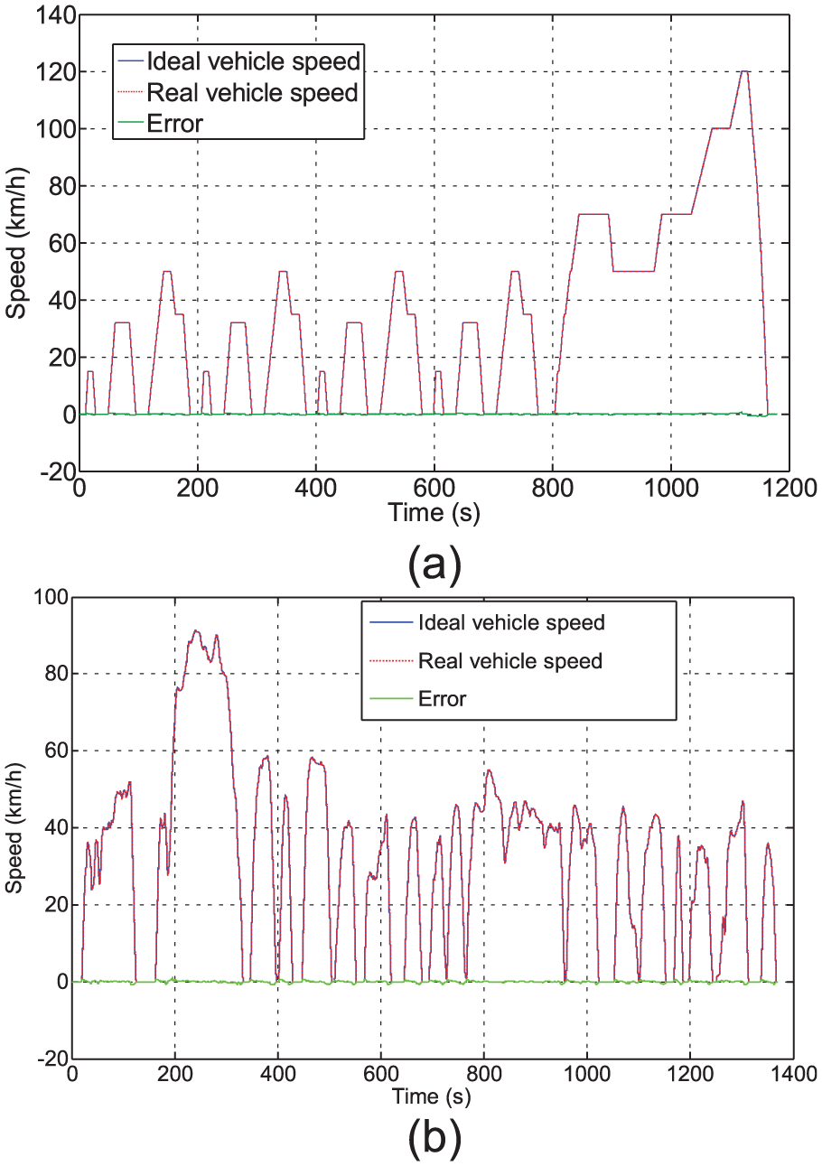
Driving cycle charts: (a) NEDC and (b) UDDS.
After implementing the proposed design factors and GA optimization method into simulation via MATLAB/Simulink platform, some simulation results are achieved and shown in Figures 8–10.

Combined efficiency of DCT and e-motor: (a) via NEDC and (b) via UDDS.

Gear ratios: (a, b) via NEDC and (c, d) via UDDS.

Clutch outer radius and number of frictional surface: (a, b) via NEDC and (c, d) via UDDS.
Figure 8 shows the relationship of efficiency change with the optimal iteration times for the powertrain system equipped with four motors. Figure 8(a) and (b) concerns the combined efficiency DCT and electric motor simulated via NEDC and UDDS, respectively. It shows that the difference between the best and worst efficiency individually is at least 3%. From Figure 8(a) and (b), it can be concluded that the comprehensive optimization of the powertrain system is necessary and significant. In addition, the iteration times are different between simulation via NEDC and UDDS. The maximum simulation iteration times via NEDC are 100, which are larger than that by UDDS. However, the difference of obtained efficiency between both driving cycles is small.
Figure 9 shows the changing relationship of optimized gear ratios and iteration times for first and second gears, respectively. Figure 9(a) and (b) is simulated via NEDC, while (c) and (d) is via UDDS. It can be concluded that the obtained optimal gear ratio could be different if simulated via different driving cycles. Figure 10(a) and (b) indicates the changing relationship of the outer radius of multi-plate wet plates and iteration times and the consequent number of clutch frictional surfaces, separately. Tables 5 and 6 present the optimized specifications for pure EVs equipped with five different motors via NEDC and UDDS simulation, respectively.
Optimal transmission specification via NEDC.

Optimal transmission specification via UDDS.

Comparing Tables 5 and 6, it can be concluded that the optimal result is different when the driving cycles are different. As the maximum torque of Mn2 is larger than other e-motors, the number of clutch frictional surfaces is more than others. Therefore, it can be summarized that when equipped with multi-plate clutch, the number of clutch plates will increase with an increase in the maximum torque.
Conclusion
This article presents a model-based methodology for the comprehensive design and optimization of a two-speed EV powertrain system. An integrated consideration of electric motor and two-speed DCT is conducted to design an EV powertrain system. The design factors include selection of e-motors, gear ratios’ boundary, multi-plate wet clutch design, and shift schedule. Additionally, this article applies the detailed drag torque model in the transmission design. Furthermore, GA method is applied using model-in-the-loop techniques to accelerate the design process and determine the optimal variables.
The results of simulations demonstrate that the difference for the combined motor and DCT efficiency between the worst and the best results can be 20% or even more when equipped with different e-motors and gear ratios. Even equipped with the same motor, the difference of powertrain efficiency can reach 15% if equipped with different gear ratios. Therefore, comprehensive design and optimization of e-motor and transmission are important. Additionally, the number of clutch plates will increase with an increase in the maximum motor output torque. Finally, the optimal results are different when run with NEDC and UDDS, respectively.
Footnotes
Appendix 1
Academic Editor: ZW Zhong
Declaration of conflicting interests
The author(s) declared no potential conflicts of interest with respect to the research, authorship, and/or publication of this article.
Funding
The author(s) disclosed receipt of the following financial support for the research, authorship, and/or publication of this article: This research was supported, in part, by the Chinese National Science and Technology Major Project (2016YFD0701100), the Chinese National Science and Technology Support Program (2015BAD18B03), and the Training Program for Outstanding Young Teachers in Higher Education Institutions of Guangdong Province (2014Yq2014025).