
Abstract
The wide applications of vector control improve the high-accuracy performance of alternating current (AC) adjustable speed system. In order to obverse the full-order flux and calculate the real-time speed, this article introduces the motor T equivalent circuit to build a full-order flux observer model, where the current and flux variables of stator and rotor are adopted. Model reference adaptive control is introduced to build the AC motor flux observer. The current output is used as feedback to build the feedback matrix. The calculation method of motor speed, which is part of the inputs of flux observation, is applied to realize the adaptive control. The concept of characteristic function is introduced to calculate the flux, of which the foundation is the variables of composite form of voltage and current models. The characteristic function is deduced as a relative-state variable function. The feedback matrix is improved and designed to ensure the motor flux observer is a smooth switch between current and voltage model in low and high speeds, respectively. Experimental results show that the feedback and characteristic model are feasible, and the vector control with speed sensorless based on the full-order flux observer has better performance and anti-disturbance.
Keywords
Introduction
Magnetic field orientation is vital in vector control (VC) method for induction motor’s speed regulation. Magnetic field orientation relates tightly to the rotor parameters. How to recognize and calculate the rotor parameters with high accuracy has become a hot issue in academia. The common method is adopting the closed-loop and installing a speed sensor in motor shaft so as to get a group of more accurate rotor parameters. However, in real applications, the installation of speed sensor faces the following limits:1–3
The installation of speed sensor reduces the simplicity and robustness of the system;
The speed sensor with high precision is usually costly;
In some specific harsh situations (e.g. high temperature and moist), the installation reduces the reliability of the system;
The improper installation would become a new source of the fault.
In order to solve these problems, VC without speed sensor has been proved a promising alternative method. The speed sensorless vector control (SSVC) is presented first by R Joetten and G Maeder 4 in 1983, who prompted the development of alternating current (AC) transmission technology up to a new level. Nowadays, there are many kinds of methods, which can be divided into several categories:5–7 model reference adaptive-control system (MRAS) method, dynamic speed estimation (DSE) method, artificial neural networks (ANNs), adaptive speed observer (ASO) method, proportional-integral (PI) regulator method, high frequency injection (HFI) method, and rotor slot harmonic (RSH) method. SSVC has many merits such as saving the speed sensor and reducing the construction and maintenance cost. It achieves a similar dynamic performance as the conventional VC with speed-loop method. Especially, SSVC improves the low-speed characteristics, the speed regulation ability in variable load situation. This method gets a stronger starting torque than conventional VC method. This characteristic brings obvious advantages in high friction and inertia load, so as to realize the complete decoupling control. Moreover, the scheme of SSVC is relatively brief. Similar to the conventional VC, SSVC includes the speed control loop, torque control loop, and flux control loop.8–10 The regulators of speed and flux also adopt the PI regulators. Unlike the conventional VC method with speed sensor, SSVC must build a flux observer and a speed observer so as to detect the real-time magnetic field orientation. SSVC also has a shortcoming;11,12 its demerit is that the rotor time constant affects greatly on the accuracy of rotor’s flux detection in flux-loop, which influences the dynamic performance of speed regulation. The SSVC system is put forward based on the VC in general, in which the speed sensor and encoder are eliminated. The parameters of flux and speed of induction motor are obtained by an online or offline observer. In recent years, the scholars are devoted to the study on speed sensorless control system because of the advantage of VC method to perform with high accuracy, which is simple construction scheme and has gradually become a hot topic in motor control field. The control system performance with SSVC depends on the accuracy and range of speed identification. How to obtain the speed and other parameters accurately plays an important role in this control method.
The common acquisition method for flux values and field orientation angle is using direct method of magneto sensitive and the detector coil detection. Moreover, the indirect method of observation model is also adopted. The direct method requires the installation of hall element in the inner surface of motor stator side, and the detector coil needs to locate in the motor slot. Although these methods are of high precision, the installation of detection element in the interior of motor is constrained by the technology and process problems, and it is vulnerable to the impact of the slot. The detected raw signals contain a lot of ripple components. The direct method is used only to the specific motor, not to move to other motors without detection device. It is not convenient to wide applications. At present, the indirect method is more prominent, which adopts the observation model. With the easily measured quantities, such as the stator’s voltage and current, the flux observation model is applied to calculate the rotor flux vector and other parameters. 13
A typical dynamic system, of which state variables are obtained through the measurement of external variables (i.e. the input and output variables), is also known as the state reconstruction device. In the early 1960s, in order to realize the state feedback control system or other requirements, DG Luenberger and RW Bass proposed the concept and construction method of the state observer. The problem on the state unmeasured directly is solved by reconstructing method. The emergence of the state observer provides a practical possibility of state feedback and has been applied in many aspects of control engineering, for example, copying disturbance to achieve the full compensation for disturbance. MRAS is introduced to meet the requirements of real-time control. This model includes the reference model, the control object, and the adaptive adjustment mechanism. It takes the output of reference model as the standard output; the adaptive mechanism compares the error between the reference model and the controlled object so as to determine the adaptive rule. With constant adjustment of the parameters or a certain auxiliary signal, the control object is constrained to change with the reference model changes. Adaptive parameter identification is to put the controlled object in the position of reference model; the adaptive mechanism does not change the adjustable parameters continuously with the error until it approaches zero, and then the final adjustable model converges to the controlled object model. This article introduces the stator flux (usually defined as virtual flux.) into the three-phase pulse width modulation (PWM) rectifier. According to the research of virtual-oriented VC and estimation of instantaneous power, this study proposes a direct power strategy without grid voltage sensors. This strategy combines the virtual flux direct power control method to the space vector modulation.
The rest of this article is organized as follows. Section “The rotor flux observation model” presents the rototiller flux observer model, such as current model and voltage model. Section “The full-order flux observer model of the induction motor” gives the full-order flux observer model of the induction motor. Sections “The full-order flux observer based on MRAS” and “The design of the feedback matrix in the full-order flux observer” explain the full-order flux observer based on MRAS. Section “Experimental and results analysis” discusses the experimental results of the framework and its comparisons. Section “Conclusion” concludes the study.
The rotor flux observation model
Magnetic field control for three-phase asynchronous motor is an important issue in speed-control system. The constant air gap flux of AC motor needs to be maintained in control under the fundamental frequency, while the weak magnetic control needs to be kept in higher fundamental frequency. The position and size of the rotor magnetic field is necessary to be recognized if the AC motor is controlled by the rotor magnetic field orientation. It means that the motor magnetic field is controlled in real time. First, the magnetic field orientation can be detected. Direct detection is difficult to achieve due to engineering environment and technological complexity. In general, the observation method is used. The most basic method on rotor flux observation includes the voltage model and the current model. The current model is divided into the two types of coordinate conditions: the one is in two-phase
The current model
Current model of the two-phase stationary coordinate system
The current model in two-phase

Current model rotor flux on two-phase
The rotor flux components on

where

Let

where
Current model in two-phase rotating coordinate system
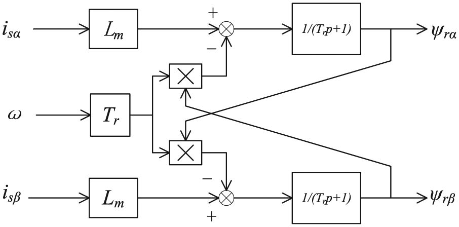
The current model in two-phase dq rotating coordinates is shown: the rotor flux current model first detected the stator currents and velocity, and then the rotor flux is calculated. The three-phase stator currents are transformed to its excitation component

The motor slip

Current model of rotor flux on dq rotating coordinate.
The voltage model
Equation (6) is obtained by the mathematical model of voltage equation of AC induction motor on two-phase

Then
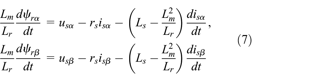
Motor magnetic flux leakage coefficient

Voltage model of rotor flux.
The full-order flux observer model of the induction motor
The basics of full-order states observer
If the controlled object is observed, its input and output are applied to rebuild the states with the states observer. If the dimension of the rebuilt state vectors equals the controlled object state vectors, this observer is called as a full-order flux observer. Full-order adaptive state observer is also called Luenberger observer. This method belongs to the range of MRAS. 14 Setting the induction motor itself as a reference model, the full-order state observer is used as the adjustable model. This method has merits of avoiding the pure integral problem, ensuring the accuracy of the reference model and reducing the sensitivity to motor parameters.
The dynamic state equation of the controlled object is set as equation (9)

According to the model of the controlled object, the simulation system with the same dynamic equation as equation (9) is built as follows as

where
The initial states of the two systems (the controlled object and the simulation system) are always different, that is, even if their parameters are identical. It exists as the state’s error between the estimation and the actual object, which leads to failure in realizing the accurate states observation. However, the state’s error results in the output’s error. According to the theory of feedback control, the output’s error between the controlled system and simulation system is built with negative feedback and controlled as soon as it approximates to zero, hence the state’s error approximates to zero. The full-order flux observer is built based on the above theory

where u and y are the inputs,
The state space model of AC induction motor
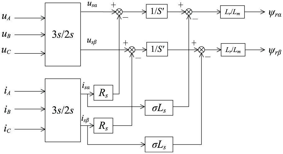
The equivalent circuit of AC induction motor has three kinds of forms: T circuit, inverse
T circuit with arbitrary angular velocity in dq coordinate.
On the premise of neglecting temperature change, skin effect, and excitation saturation, as the rotor speed is a relatively slow change in the amount of current and flux, it is seen as the constant. Therefore, the AC motor model is described by a fourth-order linear equation. The construction of the state space model needs to choose the appropriate variable. The stator current and the rotor flux are chosen to the orientation of rotor flux. The stator flux and the rotor flux are chosen to direct torque control. The state equation of AC motor in arbitrary angular velocity with rotating coordinate system is built as follows

where the total leakage inductance coefficient is
The full-order flux observer based on MRAS
The principle of the full-order flux observer is shown in Figure 5. The AC motor is the reference model and the error between the motor current and the observed current is introduced to correct the relative motor state for observation.15–17 The full-order flux observer of induction motor is the motor itself as a reference model. The state equation is built to estimate the motor flux and stator current; the stator current is used as the output current; and the actual errors estimated current is introduced as feedback correction. The gain of the feedback matrix of the correction term is adjusted to improve the performance of the full-order flux observer.

The principle diagram of the full-order flux observer of AC motor.
The complex form of AC motor equation
The complex vector form of AC motor equation: the AC motor states equation, according to the stator flux and rotor flux, is built by T equivalent circuit and equation (12)

where

The mathematic model of the full-order flux observer to AC induction motor
According to the state equation of AC induction motor, when the stator flux and rotor flux are used as the state variables, the full-order flux observer is expressed with the introduction of the current feedback, then

where
The subtraction between equations (13) and (15) can be obtained as the error equation

In the rotating coordinate system, the full-order fluxes observer model of T equivalent circuit is built with the addition of the current feedback

where
The error equation is obtained as follows
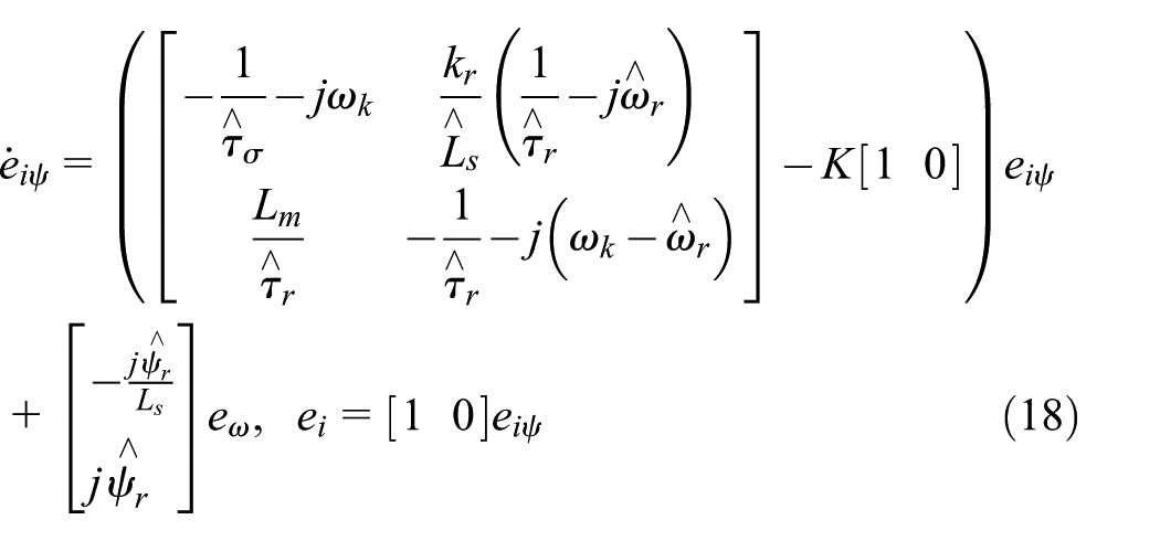
where
The speed acquisition method
Since the AC motor speed cannot be obtained directly, it is identified by the adaptive rate with the detection data. The identification equation based on the full-order flux observer is as follows

where
SSVC based on the full-order flux observation
Based on the conventional principle of VC, SSVC depends on the online or offline parameters identification to obtain the flux and speed. Recently, more scholars and researchers are interested in this control field and mainly focus on how to identify the parameters,18,19 such as speed, flux, and rotor time constant. These identification accuracies and extensions determine the control performance.
MRAS is applied to online identification of AC induction motor parameters in this article. The reference model and the adjustable model are built. The adaptive mechanism is used to adjust the parameters of the adjustable model and maintain the error between the reference model and the adjustable model to zero. This method has the better performance even if the system has dynamic changes and disturbances. The estimation of speed is introduced to the VC system with sensorless. The control system model, in this article, is built with the full-order flux observer based on MRAS. The stator current excitation and torque components have been completely decoupled before the space vector pulse width modulation (SVPWM). This control system model is shown in Figure 6.
Division of decoupling vector controlling system.
The design of the feedback matrix in the full-order flux observer
The complex form of rotor flux observer
The characteristic function
The calculation model of the flux, observed by the current model flux observation in frequency domain, is expressed as

Well, the calculation model of the flux, observed by the voltage model flux observation in frequency domain, is expressed as
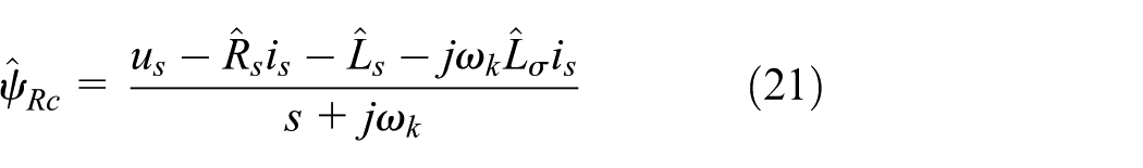
Therefore, the complex form of the flux observation is as follows
The derivation of the characteristic function
In the flux calculation model, the characteristic function combines the voltage model and current model as a reference function. Its derivation process is obtained with the transformation of equation (16)


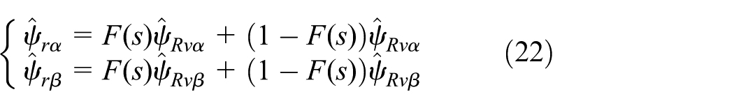
The flux calculation equation of the full-order flux observer is as follows
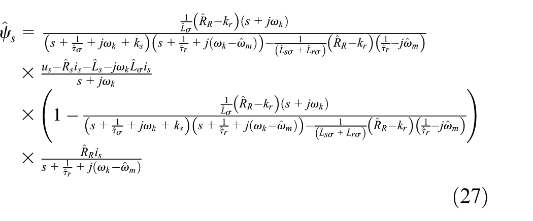
Therefore, the characteristic function is deduced as

In ideal conditions, the parameters of the full-order flux observer are designed reasonably. This flux observer can be close to the current model flux observer at low speed, while can smoothly switch to voltage model flux observer at high speed.
The design of feedback matrix
From the full-order flux observer vector model, it can be seen that, when the feedback matrix is zero, the smooth switching of this full-order flux observer could not be realized between the voltage model and current model. Moreover, the overdamped appears in this flux observer at high speed. The feedback matrix must be designed to resolve this smooth switching, in order to meet the application requirements of this full-order flux observer, whose variables are the stator flux and rotor flux at the synchronous rotating coordinate.
The conventional feedback matrix gains is

where
The feedback matrix, designed with this method, can realize the smooth switching to the voltage model and current model in the full-order flux observer. When AC motor speed is low, this observer can approximate to the current model flux observation. With the increment of AC motor speed, the parameters relative to speed also increase, this observer can achieve close to the voltage model flux observation.
Experimental and results analysis
The feedback matrix used in the full-order flux observer verified the efficiency and accuracy. The parameters involved in this flux observation model are arranged to simulate. The full-order flux observer is applied to the experiments including high, middle, and low speed of AC motor. The feedback matrix is set to zero and equation (29). The AC motor adopts the VC with speed feedback. The set value of rotor flux is 0.88 Wb. The set values of speed are 1200, 600, and 30 r/min, respectively. The comparisons between the actual flux and observed flux with these values of speed are shown in Figures 7–12.

Comparison between actual speed and identification speed and the comparison between actual flux and observed flux, speed is set to 1200 r/min, feedback matrix is set to zero.
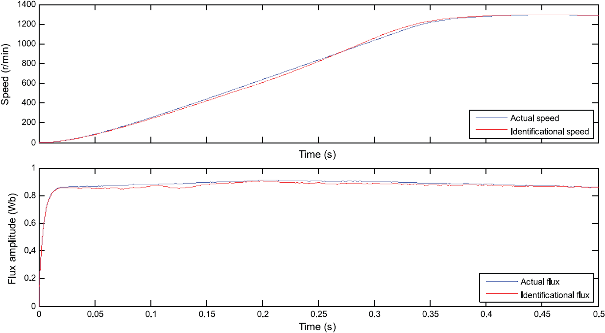
Comparison between actual speed and identification speed and the comparison between actual flux and observed flux, speed is set to 1200 r/min, feedback matrix is set to equation (29).
Comparison between actual speed and identification speed and the comparison between actual flux and observed flux, speed is set to 600 r/min, feedback matrix is set to zero.

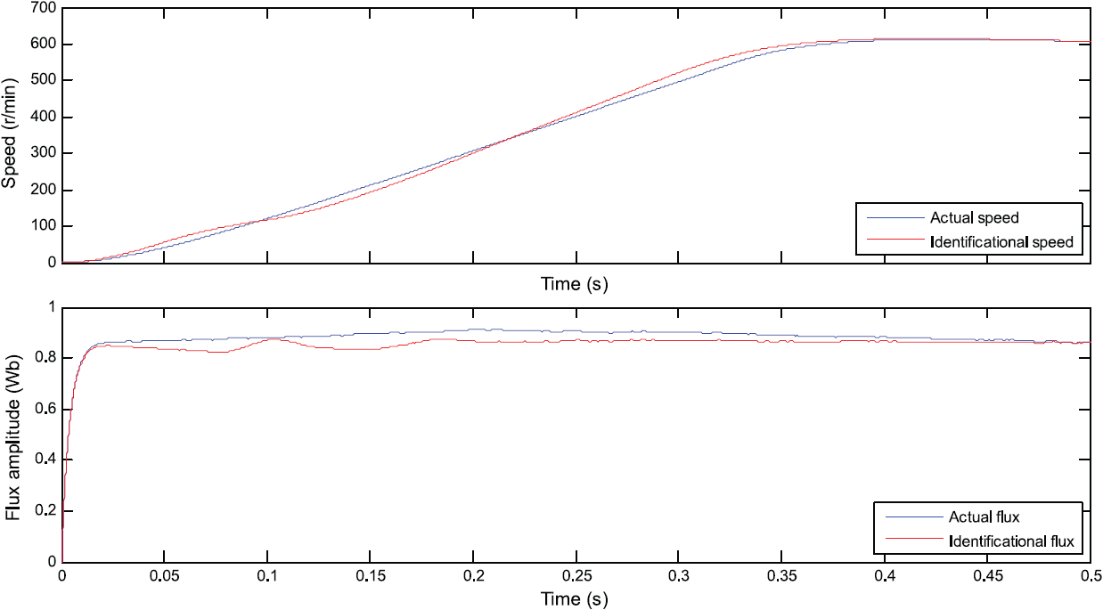
Comparison between actual speed and identification speed and the comparison between actual flux and observed flux, speed is set to 600 r/min, feedback matrix is set to equation (29).

Comparison between actual speed and identification speed and the comparison between actual flux and observed flux, speed is set to 30 r/min, feedback matrix is set to zero.

Comparison between actual speed and identification speed and the comparison between actual flux and observed flux, speed is set to 30 r/min, feedback matrix is set to equation (29).
From the calculation model of feedback matrix and characteristic function, it is known that when the motor speed is low, the flux observation is close to the current model; when the motor speed is relatively high, the calculation model is close to the observation of the voltage model. As the motor speed is low, the identification speed can be very good to follow the actual speed; the actual flux and observation flux are basically coincident. These simulation results are relative to that the feedback matrix can be good to make the full-order flux observer close to current model flux observer in motor low-speed running area, and the stability of current model flux observer in motor low-speed running is better. At the same time, when the feedback matrix is not zero, the speed response increases compared with the feedback matrix is zero, which improves the anti-interference ability and the convergence.
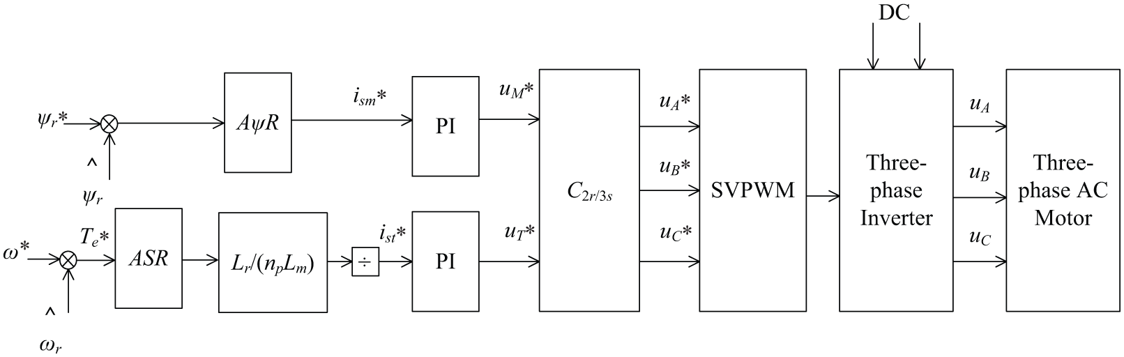
This article introduces a compound form of current–voltage model, of which an instantiated current–voltage feedback matrix loop is applied on the motor mathematical model. By means of feedback matrix, the model of motor is close to the current system model in low rotating speed and matches to voltage system in high rotating speed. In this article, the full-order flux observer based on MRAS is adopted to observe the flux and estimate the speed. The diagram of VC system without sensors is shown in Figure 13.
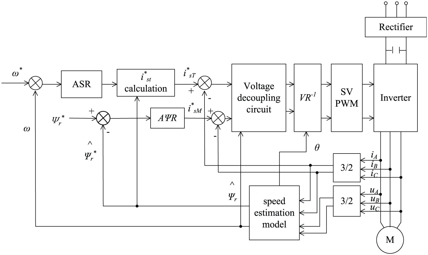
A vector control system with speed sensorless block diagram.
MATLAB/Simulink is applied to verify the proposed VC of speed sensorless with the full-order flux observer based on MRAS. This simulation parameters of AC induction motor are as follows: rated power is 4 kW, rated voltage is 380 V, rated frequency is, the pole number is 2, stator resistance is 0.435 Ω, stator leakage inductance is 0.002 mH, rotor resistance is 0.816 Ω, rotor leakage inductance is 0.001 mH, mutual inductance is 0.069 mH, and moment of inertia is 0.19 kg m2. The simulation results are shown as follows. Figure 14(a) shows the actual speed and identification speed in rated frequency 50 Hz. It is obvious from Figure 14(b) that the speed error converges rapidly and is near zero from 0.5 s. The torque waveform of AC motor is shown in Figure 14(c).

The motor torque and speed waveforms: (a) actual speed and identified speed, (b) speed error, and (c) torque waveform of AC motor.
Experiments are accomplished in the AC motor control system platform to test the performance of VC with speed sensorless based on MRAS. Space vector modulation switching bridge signals with dead time are shown in Figure 15(a): switching frequency is 9.4 kHz and dead time is 1.4 µs. Figure 15(b) and (c) shows the inverter output voltage and current waveforms of phase u. With the analysis of these experimental results, the control system that applied the proposed method has better performance and dynamic response ability. From these figures, it is obvious that the estimated speed can well follow the actual speed of the motor, which achieves a good identification result, and the system error can get convergence, which verifies the stable operation of the system and explains the design of VC system is feasible.
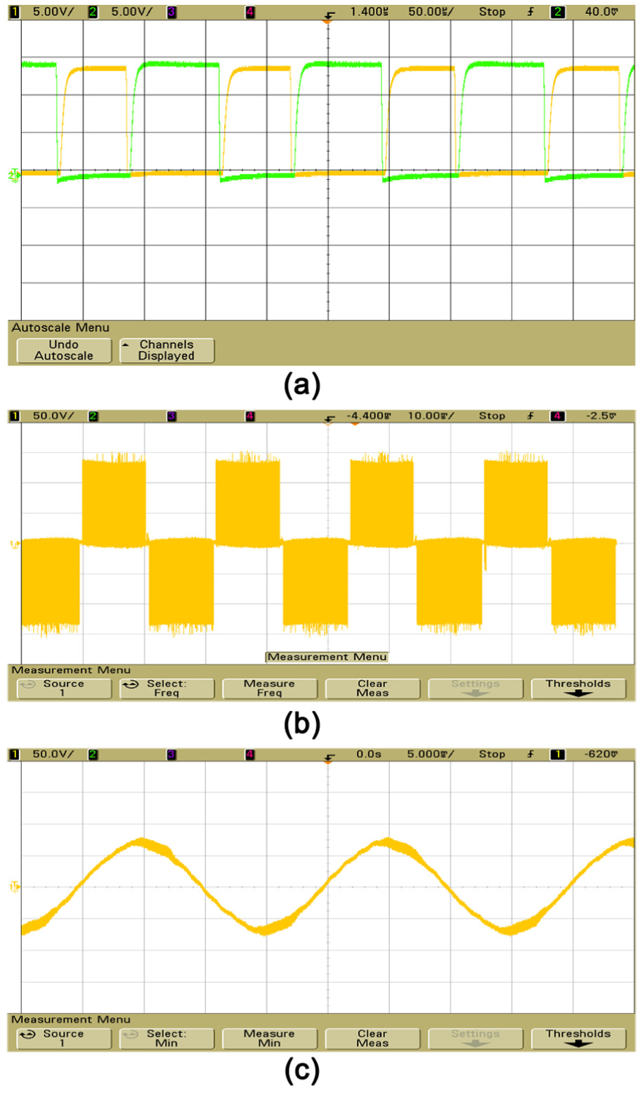
The output current and voltage of inverter: (a) SVPWM signals, (b) output voltage of inverter, and (c) output current of inverter.
Conclusion
The main problem in VC of AC drive is the parameters’ identification, such as resistance, inductance, and flux of stator and rotor. The SSVC system pays more attention to flux observation and speed estimation. The full-order flux observer is improved for observation on flux. The dual-model composite method is applied to estimate flux. The observation model and speed estimation model are built based on model reference adaptive control. The feedback matrix is introduced to improve the feedback gains, in order to meet the smooth switching of observation model, in which the current model is obtained in low speed and the voltage model is used in high speed. According to this identification method, the VC system with speed sensorless based on full-order flux observer is proposed in this article. The identification results of speed and flux are used as inputs to regulate the various control quantities. The decoupling circuit, 2r/3s transformation and SVPWM are applied to realize the VC of AC motor. Experimental results show that the proposed method has better dynamic responsibility and anti-disturbance.
Footnotes
Academic Editor: Pak Wong
Declaration of conflicting interests
The author(s) declared no potential conflicts of interest with respect to the research, authorship, and/or publication of this article.
Funding
The author(s) disclosed receipt of the following financial support for the research, authorship, and/or publication of this article: This work was supported by the National Natural Science Foundation of China (U1404512 and 61473115) and the Project of Luoyang Science and Technology Development Plan (1401017A). This work was also supported by the University of Macau under Grants (MYRG2015-00077-FST).