
Abstract
During the operation of speed-sensorless control system for induction motor, the stator and rotor resistance varies greatly with the change of temperature and the frequency of the rotor side, which affects the estimation of the stator flux and leads to the low accuracy of the speed estimation. A speed-sensorless vector control method based on parameters identification with the full-order adaptive state observer is proposed in this paper. In the model reference adaptive system of AC motor, the stator resistance and rotor flux are assigned as state variables to build the reference model, and a full-order flux observer is introduced to adjustable model. Lyapunov theory and Popov superstability theory are used to deduce the speed and rotor resistance adaptive rate. The feedback gain matrix is simplified to speed up the convergence rate of the system. The estimation values of speed and rotor resistance are taken as the proportional integral form, so that an interactive model reference adaptive system is constructed by speed and rotor resistance identification. While observing the rotor flux, it can not only ensure the accuracy of the reference model but also eliminate the disadvantages of the voltage model with integral terms, and the rotor speed can be estimated at the same time. The experimental results show that the accurate performance of speed and flux identification can meet the requirements of application; the proposed control method with the identification of speed and rotor resistance has little fluctuations phenomenon on motor torque in low speed and achieves better performance.
Keywords
Introduction
The installation of speed sensors in induction motors can cause difficulties in installing and repairing motors. Since 1970s, the speed-sensorless vector control of induction motors has been studied in the field of motor control. As we all know, in vector control systems of induction motors, it is necessary to obtain the flux value. The accuracy of the flux linkage phase and amplitude observation directly affects the performance of the vector control system. Therefore, how to accurately observe the flux linkage is a key problem in the flux linkage observation. The parameter identification methods of speed-sensorless vector control mainly include direct calculation method, recursive least square (RLS) method, model reference adaptive system (MRAS) method,1–3 rotor tooth harmonic method, extended Kalman filter (EKF) method, extended Luenberger observer (ELO) method, 4 high-frequency injection method, and neural network method.
The vector control of induction motor has excellent dynamic performance because it realizes the decoupling control of excitation current and torque current of the rotor. However, in actual operation, the rotor resistance changes greatly with the variation of its temperature and rotor side frequency, which has an effect on the estimation of the stator side flux and the accurate estimation of the speed. The high-performance vector control system relies on accurate identification of rotor resistance. Therefore, it is important to study the rotor resistance identification of speed-sensorless vector control system. Rotor flux observation is a very important physical quantity in three-phase induction motor based on rotor field–oriented vector control. The MRASs based on current and voltage model are the most widely used. These algorithms are relatively simple and do not require high performance controllers. However, voltage model involves some problems, such as stator resistance variation and integral drift during motor operation.
In the literature, 5 the improved current and voltage model errors are used to construct the speed signal, which avoids the problem of low-speed signal distortion. At the same time, it adds filter correction link to improve the anti-interference but ignores the distortion of the over speed. In this paper, the stator current and rotor flux linkage are adopted as state variables to construct asynchronous induction motor state equation. At the same time, the synthetical situation of the motor at low speed and high speed is considered. In the literature, 6 a new method of stator flux offset calculation and feedback compensation is adopted. Finally, the stator flux offset is eliminated, but the calculation is complicated. A full-order flux observer is introduced to adjustable model in this paper. Lyapunov theory and Popov superstability theory are used to deduce the speed and rotor resistance adaptive rate, in which algorithms are relatively simple. In the literature, 7 the rotor flux, stator resistance, and rotor speed are identified by the whole-order flux observer, but it ignores the rotor resistance changing with temperature. The full-order adaptive state observer designed in this paper takes into account the variation of rotor resistance with temperature and frequency. An interactive MRAS is built with identification of speed and rotor resistance. When the rotor flux is observed, not only the accuracy of the reference model is ensured but also the disadvantages of the voltage model with integral terms are eliminated, and the rotor speed can be estimated at the same time. The feedback matrix used in the literature 8 is too complex. In the literature, 9 the selected range of feedback gain coefficients is derived by using the Rouse criterion. In this paper, the identification method of rotor resistance value is deduced with Popov superstability theory, and the feedback gain matrix is simplified, so as to speed up the convergence rate of the system.
The rest of this paper is organized as follows. The “Full-order state observation model of induction motor” section gives the full-order flux observer model of the induction motor based on the stator current and rotor flux linkage. The “Derivation of speed adaptive rate” section elaborates the Lyapunov stability theory and Popov superstability theory that are used to derive and prove the speed adaptive rate separately. In the “Rotor resistance identification” section, with Popov superstability theorem, rotor resistance is identified on the basis of speed estimation and stator resistance estimation. The “Feedback matrix design” section provides simplified form of feedback matrix for accelerating the convergence rate of the system. The “Experiment and results analysis” section discusses the experimental results of the framework and its comparisons. The “Conclusion” section concludes the study.
Full-order state observation modelof induction motor
The full-order adaptive state observer belongs to the MRAS method. MRAS is composed of reference model, adjustable model, and adaptive mechanism. Establish a mathematical model for the system to be measured, and set it as a reference model. An adaptive mechanism is designed to make the output error of the reference model and the adjustable model infinitely close to zero, so as to achieve the identification of the reference model. The common MRAS structures are parallel, series, and series–parallel models. The parallel model is shown in Figure 1.10,11
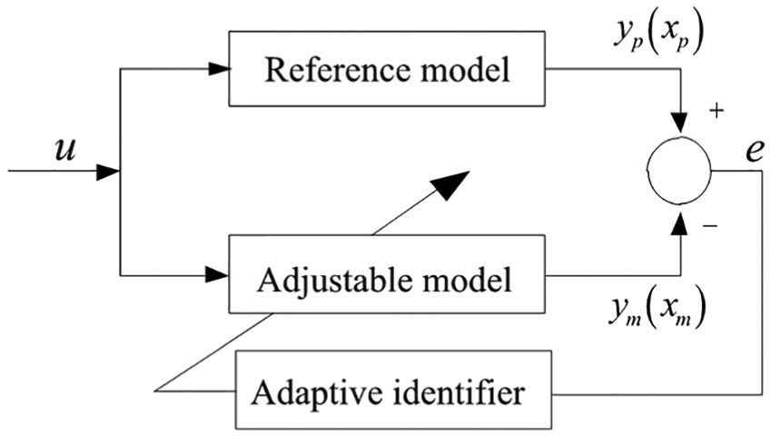
The basic structure of parallel MRAS.
In the full-order adaptive state observer, the motor is used as the reference model and the full-order state observer as the adjustable model. This method, while observing the rotor flux linkage, not only ensures the accuracy of the reference model but also eliminates the drawbacks of the voltage model with the integral term and ensures the accuracy of the reference model, reduces the sensitivity of the parameters of the motor, and estimates the rotor speed.
As state variables, the stator current and rotor flux are considered as state equations 12
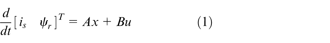
where
The output equation is defined as

where
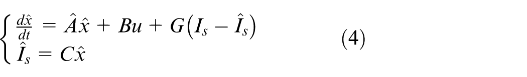
According to the model of the controlled object, an adjustable model with the same dynamic equations (1) and (2) can be constructed as follows
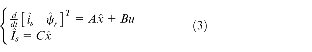
where
When the adjustable model is the same as the reference model and the initial state is the same,
where
The basic structure of full-order flux observer.
Derivation of speed adaptive rate
The speed identification system of full-order adaptive state observer is a nonlinear system. The derivation of speed adaptive rate and the stability of the system can be proved by Lyapunov stability theory and Popov superstability theory. Based on these two theories, the same results can be achieved. It is necessary to provide the illustration and calculation according to these two theories, respectively.
Lyapunov stability analysis
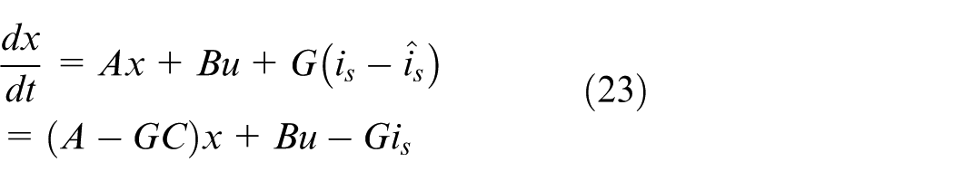
The spatial state deviation equation is obtained by subtracting equation (1) from equation (4)
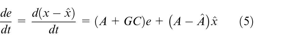
where e is the error between the real state value and the estimation state value.
When the error e is equal to 0 or infinity tends to 0, the speed can be considered to be equal to or approximately equal to the actual value. At first, the Lyapunov function is constructed as
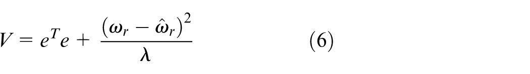
where
When
Meanwhile, in order to confirm whether the derivative of V is negative, derivation and simplification of V is obtained as follows
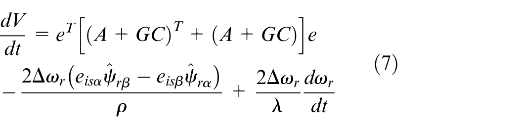
where
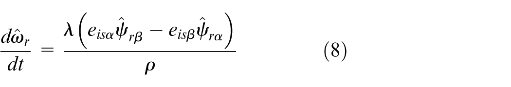
In order to speed up the convergence, the form of proportional integral (PI) is applied to identify the speed
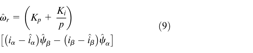
where Kp and Ki are the proportion coefficients. The electromagnetic torque can be expressed as
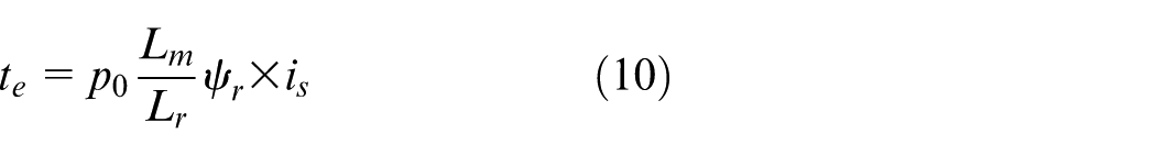
where p0 is the pole count of the motor and equation (9) can be changed as
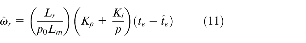
With the adjustment of the PI regulator,
Popov hyperstability theory
The basic idea of Popov hyperstability theory is as follows: a system consists of a linear forward channel and a nonlinear time-varying feedback channel; the transfer function of the forward channel is strictly a necessary and sufficient condition for the asymptotic stability of the system; if the forward channel is strictly positive, the feedback channel is satisfied with the Popov inequality; if the proper adaptive law is chosen, the nonlinear time-varying system is super stable; and the parameters of the adjustable model are changed according to the error, so that the system errors of the output parameters and the reference model tend to zero. As shown in Figure 3, the feedback system consisting of the forward linear constant link L and the nonlinear time-varying link NL is a typical system for the application of Popov hyperstability theory.
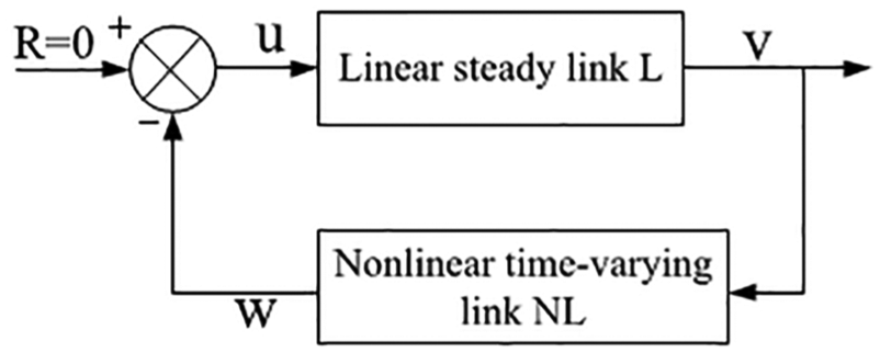
The standard nonlinear time-varying feedback system.
Equation (5) is rewritten as
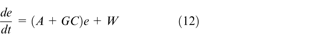
where W is a nonlinear time-varying channel and
According to Popov hyperstability theory, in order to guarantee the asymptotic stability and get the speed identification, the nonlinear part should satisfy the Popov inequality
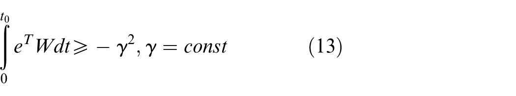
It is further deduced as follows
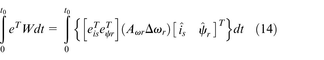
From below
It is known that equation (14) meets the Popov hyperstability theory. If equation (12) wanted to be asymptotically stable, the speed adaptive ratio can be expressed by equation (9).16–18
Rotor resistance identification
In the process of vector control on induction motor, the premise of good motor control performance is an accurate judgment of the motor parameters. The main parameters affecting the performance of the induction motor involve motor stator and rotor resistance, stator inductance, and mutual inductance, while changes of stator and rotor inductance can be ignored. However, due to the change of temperature, magnetic saturation, and other reasons, the stator resistance value of the motor and the rotor resistance value will change with the motor running, which will directly affect the difficulty of flux observation. If the flux field control is not accurate enough, it will cause the system to lose accurate and fast dynamic performance, and have effect on motor speed regulation performance.
The expression of winding resistance changing with motor temperature is shown as follows

where α is the resistance temperature coefficient, that of aluminum material is 0.0042 (1/K) and copper material is 0.0039 (1/K).
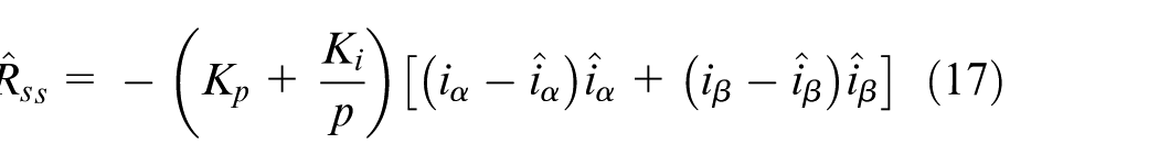
The rotor resistance value will change with the motor running. This phenomenon will influence the current model, lead to an inaccurate prediction of the flux, cause current fluctuations, and make the induction motor operation not smooth. Therefore, the identification of rotor resistance is very necessary. In order to guarantee the state convergence, the full-order observer is adopted, and the Popov hyperstability theory is used to identify rotor resistance based on the estimation of the rotor speed and stator resistance,19,20 in which the current model of rotor resistance phase is avoided at root.
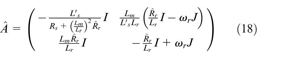
The rotor resistance of the A matrix in the state equation is changed to an adjustable parameter
According to
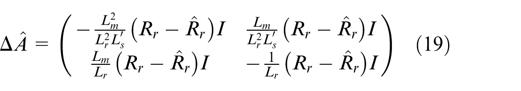
From equation (1) to equations (4) and (19), the rotor resistance identification equation can be obtained as follows
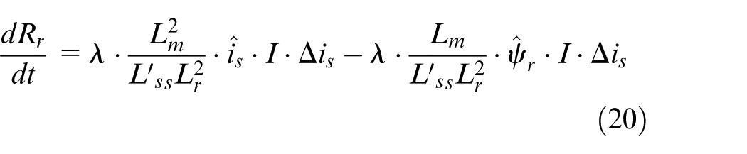
Integrating and expanding equation (20), the adaptive identification equation of rotor resistance is developed as follows
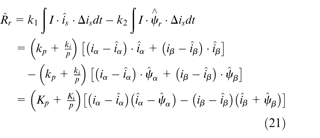
Because the change rate of flux and current is much greater than that of induction motor rotor speed, it can be considered that the speed change is slow. The error between the observed value and the actual value can be considered as approximately zero. In the digital control system, the rotor resistance
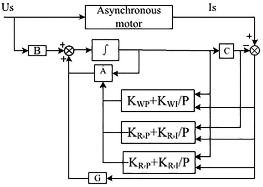
The parallel model reference adaptive algorithm structure.
Feedback matrix design
The gain matrix plays a weighting role in the system. When the output of the observer deviates from the actual output, the dynamic response of the observer is adjusted by the weighted action of the correction link and the gain matrix.
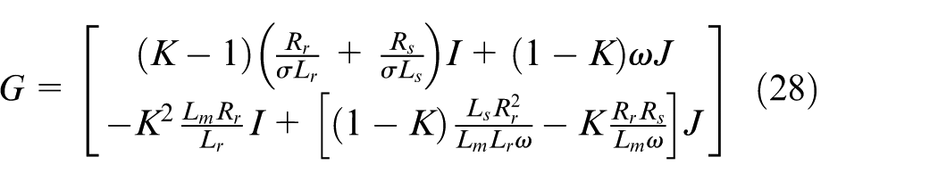
In order to facilitate computation, the A matrix in the state equation (1) can be written as
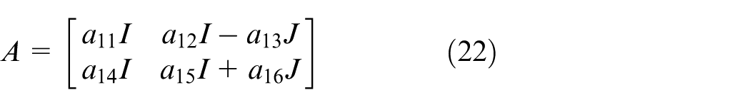
A state observer is constructed by the deviation of the stator current state estimate and the actual measurement value
where
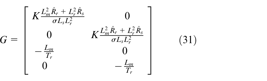
Gain matrix is as follows
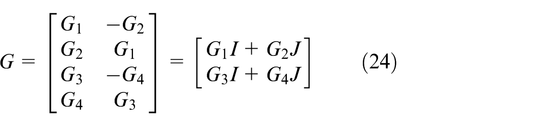
then
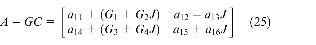
The characteristic equations are solved by equations
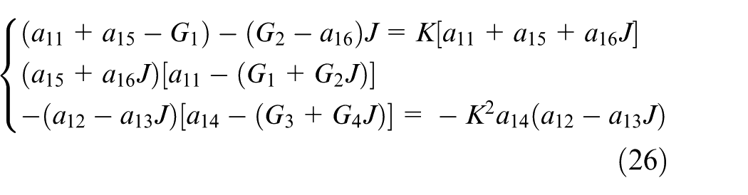
The above equations are solved as follows
The gain matrix is obtained as follows
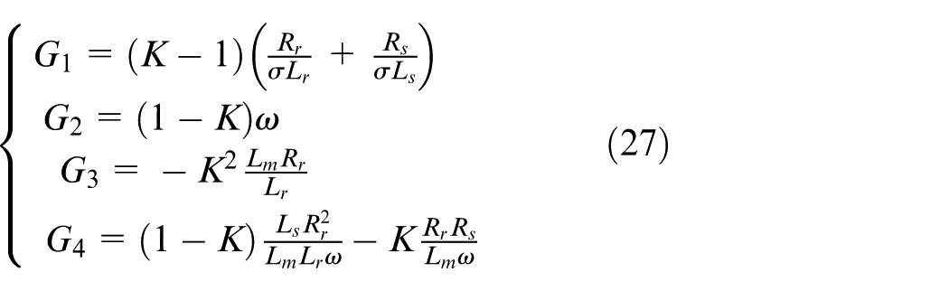
Because the mathematical model of motor is time-varying, the above method is a little complicated and difficult to be used in practice. In order to make the algorithm easy to implement and to speed up the convergence, the method of simplifying the feedback matrix is adopted; the
Let G2 = G4 = 0, G3 = Lm/T, then
It is only to change G1 to adjust the poles P1 and P2, so the simple calculation is good for the operation.
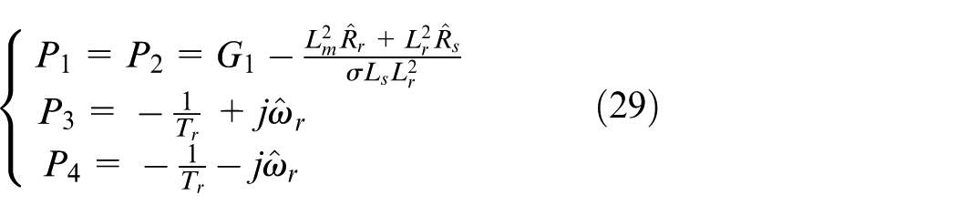
Assume that
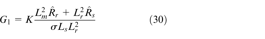
where P1 and P2 contain the same expression that is favor to the calculation; the new obtained equation is as follows
The larger the value of K is, the faster the convergence speed of the observer is. However, if the K value is too large, it will increase the sensitivity of the observer to the interference signal and affect the stability of the system. The value K is set to 1.5.
Experiment and results analysis
Simulation and analysis
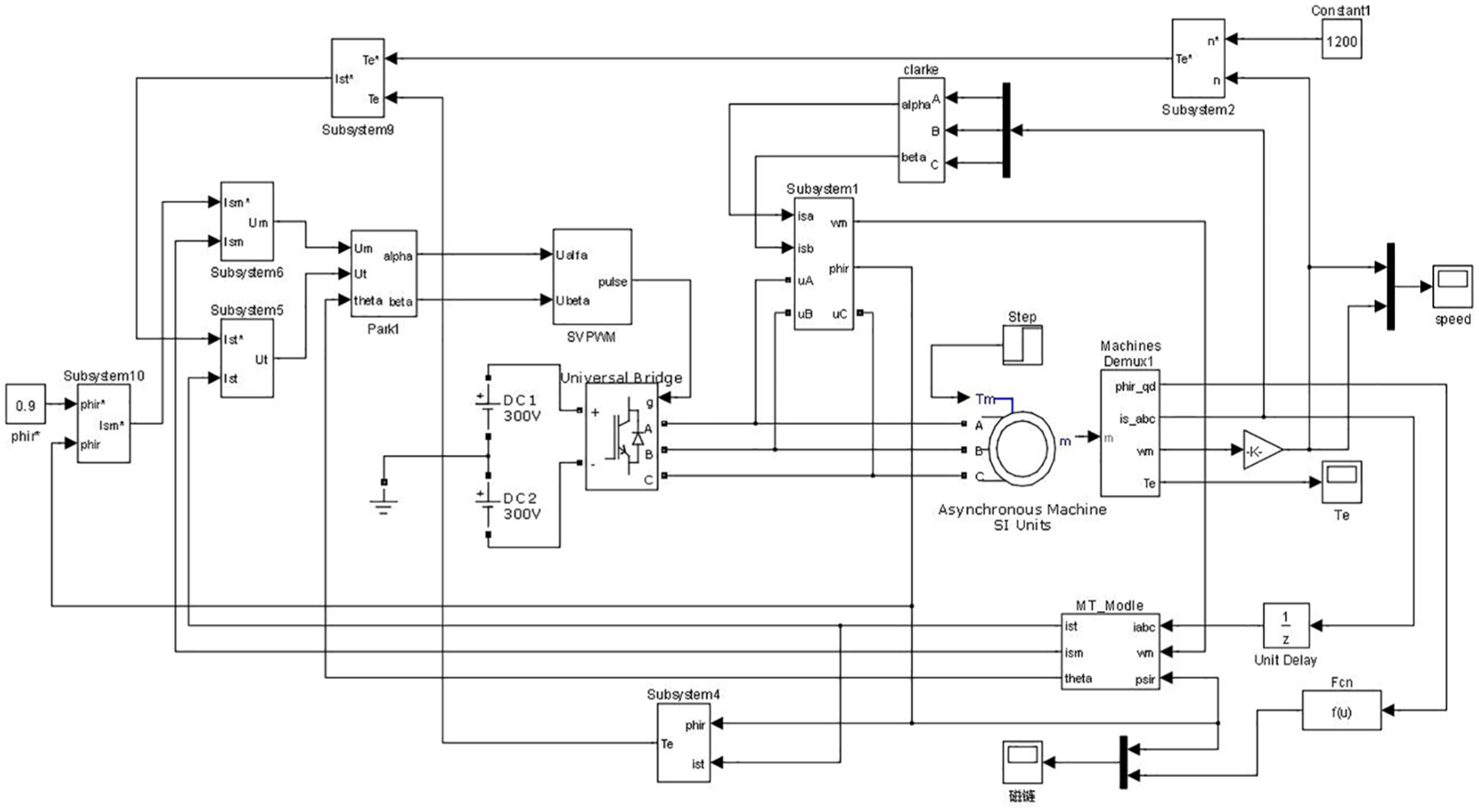
In order to verify the valuably of this proposed method, a simulation platform of the induction motor full-order state observer is set up by MATLAB/Simulink, shown in Figure 5. SVPWM technology is applied in this platform. The speed, flux, and other physical quantities of AC motor can be collected during the operation of the motor. The simulation parameters are set as follows: stator resistance, Rs = 0.2147Ω; resistor rotor, Rr = 0.2205Ω; stator winding leakage inductance, Lls = 0.0025H; rotor coaxial equivalent winding mutual inductance, Lm = 0.0697H; motor pole number, P0 = 2; inertia, J = 0.1933 kg m2; voltage, 380 V; frequency, 50 Hz; DC bus voltage, 600 V; motor power, Pn = 4.7 kW; and set speed, 1500 r/min.
The simulation waves of actual speed and estimated speed.
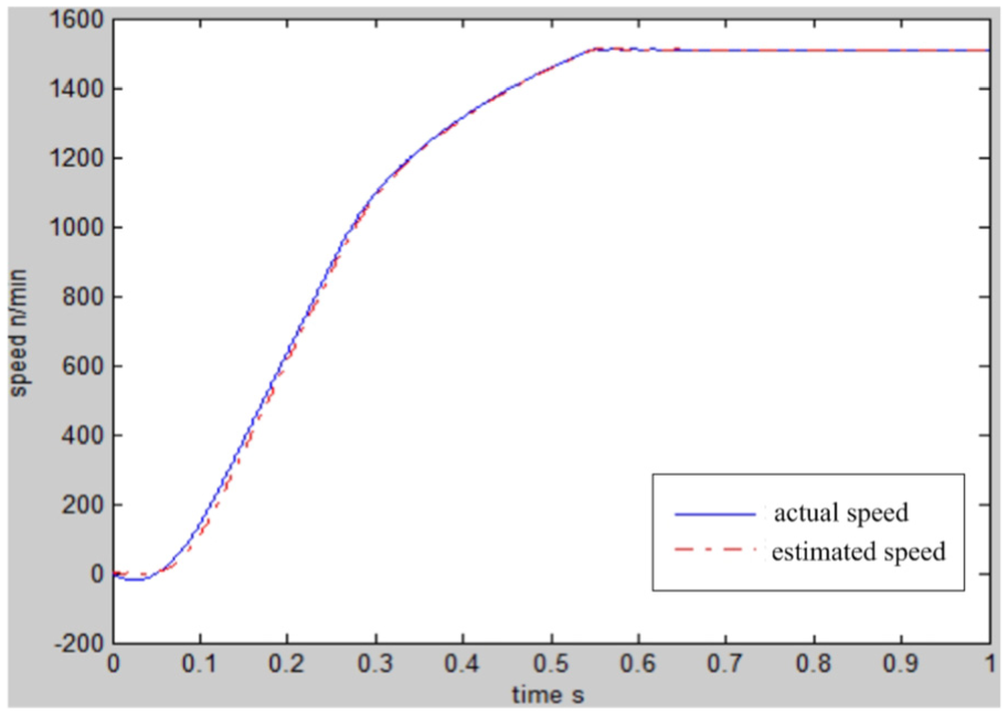
The simulation waves of actual speed and estimated speed are shown in Figure 6. At the beginning, the estimated speed is faster than the actual speed, which is slightly slower than the actual speed during the rising process. At the same time, the two speed curves coincide when they reach the predetermined speed.
The simulation waves of actual speed and estimated speed.
Figure 7 shows the simulation waveforms of observed flux and estimated flux. Figure 7(a) shows the observed flux linkage, and Figure 7(b) shows the estimated flux linkage. In Figure 7(c), y1 is the estimated flux linkage and y0 the observed flux linkage. It is obvious that the estimated flux is basically close to the observed flux linkage.
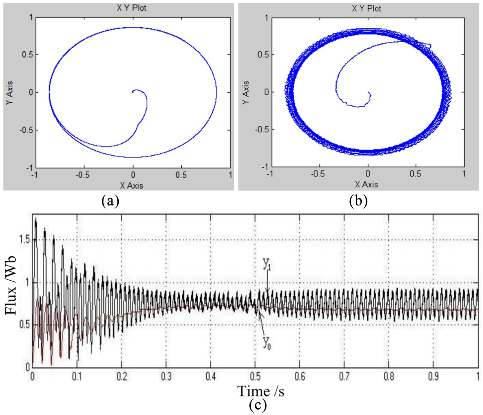
The simulation waveforms of observed flux and estimated flux: (a) the observed flux linkage, (b) the estimated flux linkage, and (c) the contrast diagram of the observed flux linkage and the estimated flux linkage.
Experiment and analysis
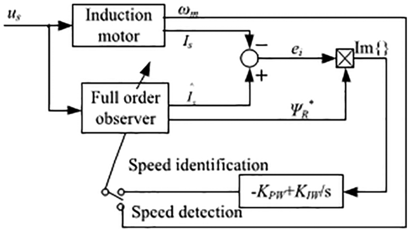
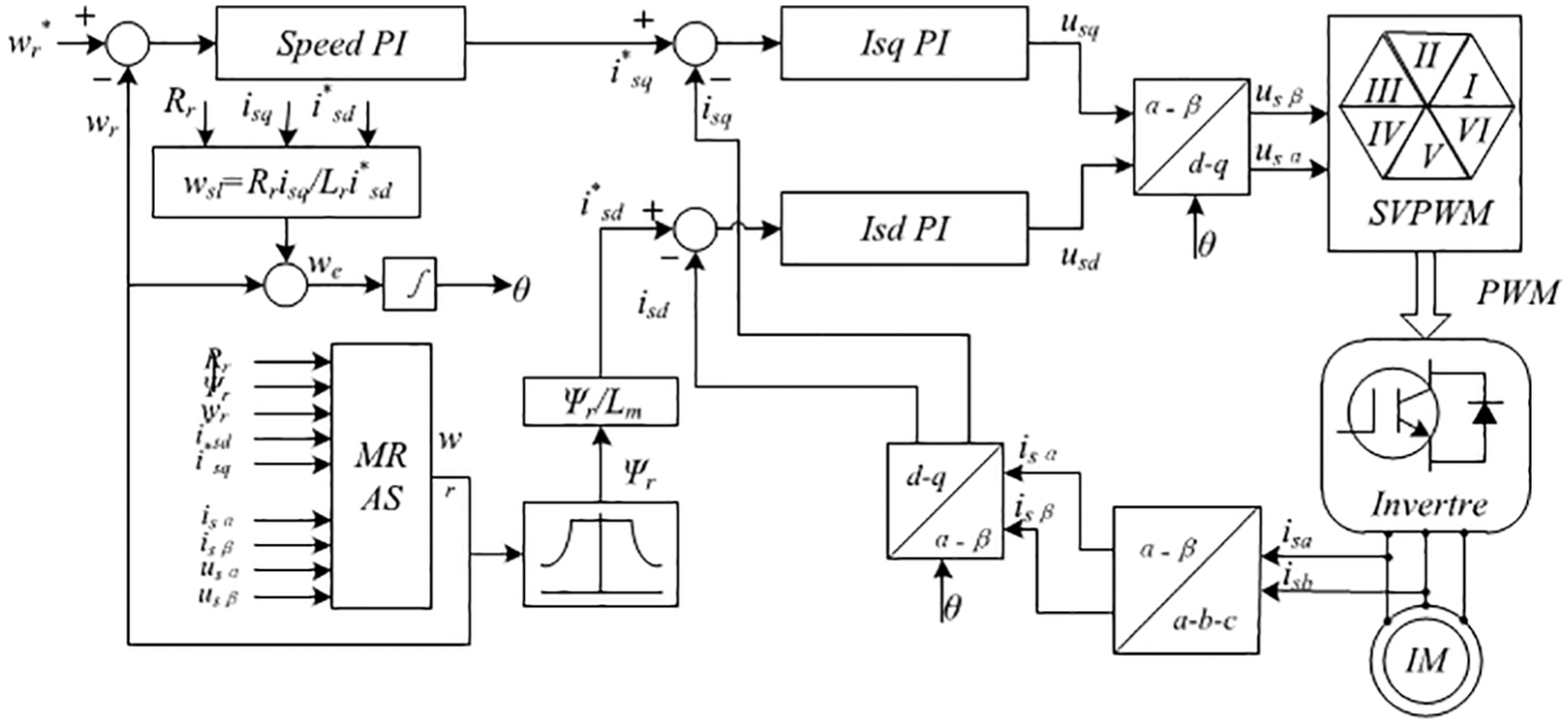
A block diagram of speed-sensorless vector control system based on MRAS structure is shown in Figure 8. The experimental parameters are set as follows: the rated voltage is 380 V, the rated frequency is 50 Hz, the number of poles is 2, Pn = 10 kW, nN = 1455 r/min, Rs = 1.375Ω, Xs = 2.43Ω, Rr = 1.04Ω, Xr = 4.4Ω, Rm = 8.34Ω, and Xm = 82.6Ω.
The simulation waves of actual speed and estimated speed.
Experiments are accomplished in this platform to verify the performance of vector control with speed sensor-less based on MRAS’. Space vector modulation switching bridge signals with dead time are set as follows: switching frequency is 10 Hz and dead time is 2.5 µs. The rotor resistance identification wave is shown in Figure 9. There are some fluctuations at the beginning, which is to adjust the process of system identification. The identification process is very short and it is about 0.04 s. The rotor resistance value is about 1Ω.
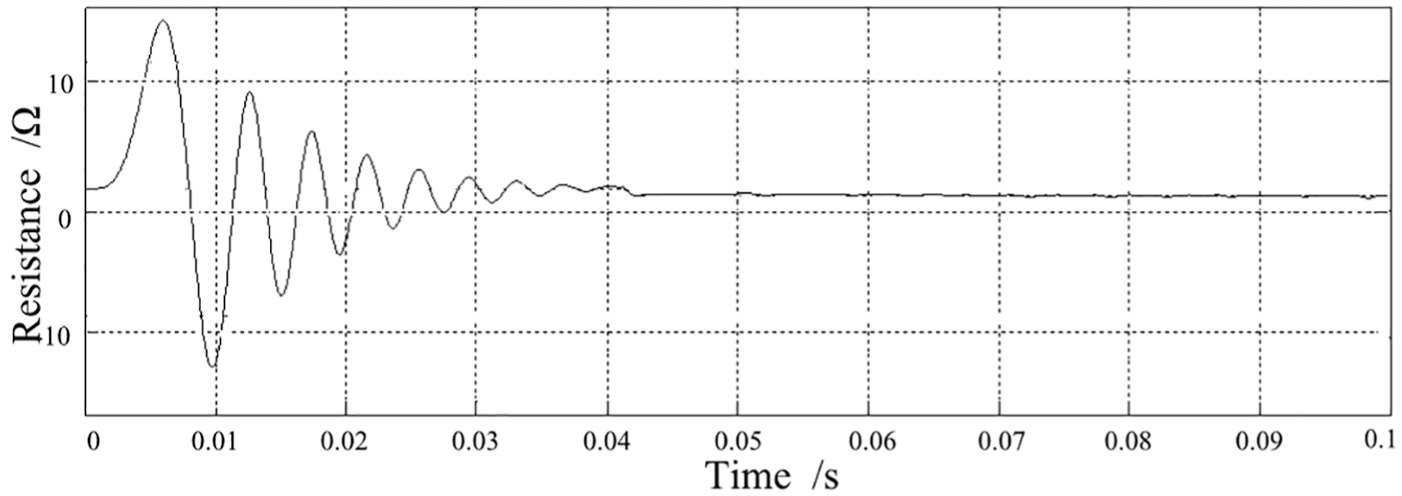
Rotor resistance identification.
Figure 10 shows the error of estimated speed, which convergent approximate to zero at about 0.5 s and expresses the stable operation of the system.
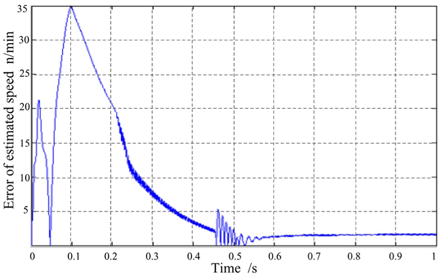
The waveform of error convergence.
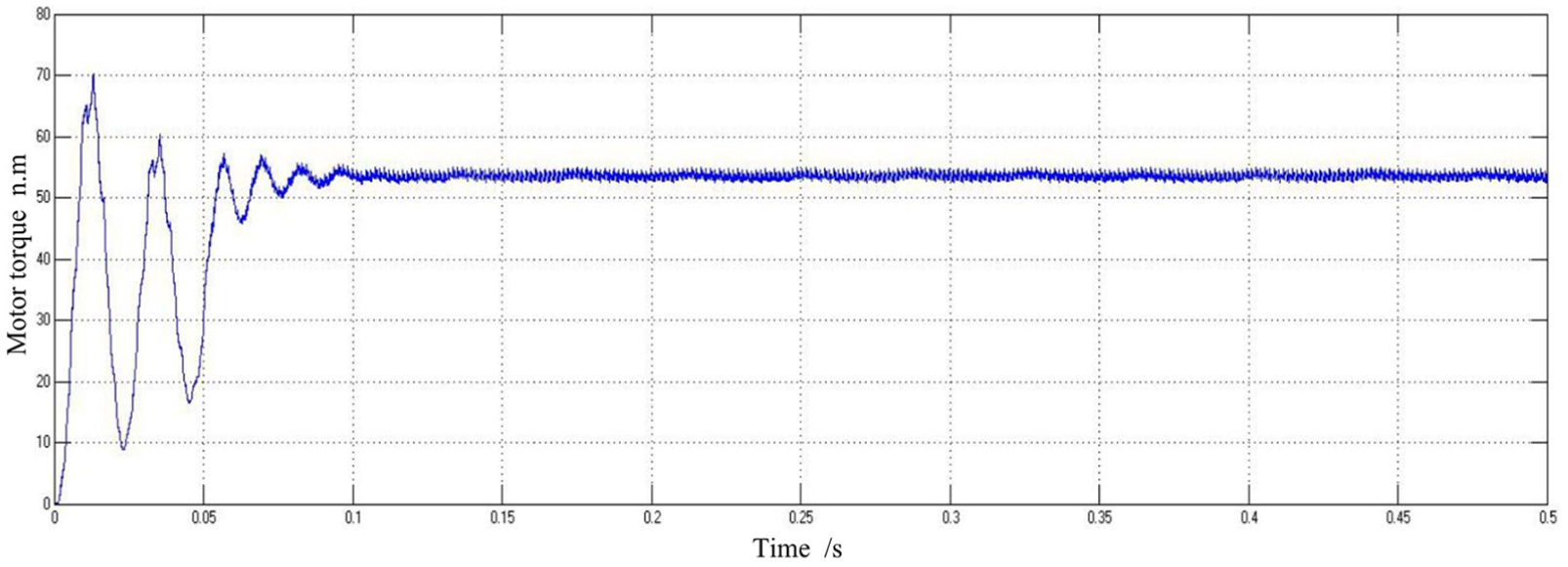
Figure 11 shows the waves of motor torque, which is stable at about 0.1 s and tests feasibility of this designed vector control system.
The diagram of sensorless vector control IM drive based on MRAS.
Conclusion
High-performance vector control system relies on accurate identification of rotor resistance. Therefore, it is important to study the rotor resistance identification of sensorless vector control system in depth. The identification of stator resistance and rotational speed has been realized in the method of full-order state observer in previous literatures. In this paper, based on Popov superstability theorem, a rotor resistance identification method based on full-order state observer is proposed, and an asynchronous motor vector control system for rotor speed identification is established, which realizes speed identification. Because the full-order state observer can identify the stator and rotor resistance at the same time, it improves the problem of variable resistance caused by stator and rotor resistance in the operation of induction motor, and eliminates the drawbacks caused by the integral term in the voltage model. In order to accelerate the convergence speed of the motor control system, the method of simplifying the feedback matrix is introduced. In order to accelerate the convergence of the motor control system, the simplify the feedback matrix is introduced. Within the MATLAB / Simulink, the identification speed and actual speed are compared and analyzed as well as the same to identification flux and actual flux. Experimental results show that the rotor resistance and motor speed are identified accurately, which can meet the industrial application requirements; because the change of induction motor resistance will have a greater effect on vector control at low speed, coupled with the rotor resistance identification, the control system has little fluctuations phenomenon on motor torque and achieves better performance.
Footnotes
Declaration of conflicting interests
The author(s) declared no potential conflicts of interest with respect to the research, authorship, and/or publication of this article.
Funding
This work was supported by the National Key Research and Development Program of China (2017YFB0306403) and the National Natural Science Foundation of China (U1704157 and 61473115).