
Abstract
Sour or sweet oil fields development is common in recent years. Casing and tubing are usually subjected to pitting corrosion because of exposure to the strong corrosion species, such as CO2, H2S, and saline water. When the corrosion pits formed in the casing inner surface, localized stress concentration will occur and the casing strength will be degraded. Thus, it is essential to evaluate the degree of stress concentration factor accurately. This article performed a numerical simulation on double pits stress concentration factor in a curved inner surface using the finite element software ABAQUS. The results show that the stress concentration factor of double pits mainly depends on the ratio of two pits distance to the pit radius (L/R). It should not be only assessed by the absolute distance between the two pits. When the two pits are close and tangent, the maximum stress concentration factor will appear on the inner tangential edges. Stress concentration increased by double pits in a curved casing inner surface is more serious than that in a flat surface. A correction factor of 1.9 was recommended in the curved inner surface double pits stress concentration factor predict model.
Introduction
Corrosion failure caused by H2S or H2S/CO2 containing multiphase flow has affected the normal operation of the oil field, some production wells have to be shut down in a severe corrosion case. Kermani has reported that over 25% of failures in the oil and gas industry are related with corrosion. More than half of these failures are associated with produced oil and gas containing H2S and CO2.1,2 Most of the corrosion failures are starting from corrosion pits and then developing into a perforation and leaking. It is significant to conduct an investigation on pitting corrosion in the presence of H2S and CO2 environment of production pipeline or tubing.3–5 Additionally, the corrosion process is also related to the structure mechanical stress, which could accelerate the corrosion rate in some circumstance. 6 Thus, the stress level on the casing, especially the stress level around the corrosion pits needs to be evaluated properly.
Stress concentration is a stress increasing phenomenon in which geometric shapes change dramatically. Most of them occurred around closed angles, cavities, gaps, and grooves. The magnification of the stress concentration usually is expressed by the elastic stress concentration factor (SCF). SCF calculation model could be divided into two types. One is considered as a semi-infinite body having a hemispherical pit located on the plane’s surface. This problem was first studied by Eubanks, 7 and he presented the analytical solution, but the calculate process was very complicated and few applications appear in later research documentation. Another model is an infinite diameter cylinder with a spherical cavity; at the weakest section (excluding the spherical cavity), Timoshenko and Gere 8 theory can be used to calculate the SCF. The stress distribution calculation model of spherical defect in infinite radius cylinder is shown in Figure 1.

A circular cylinder with a center spherical cavity.
According to the theory of elasticity, the infinite boundary problem (b→∞), in x–y plane except defect, axial load

where

The SCF can be defined as

Poisson’s ratio of steel is between 0.25 and 0.3, and the corresponding SCF is almost kept at a constant of 2.0. The SCF analytical method for a single pit was latterly well studied by Sun et al. 9 and Wang. 10
However, analytical solution for the SCF of double pits was not clear by for now. B31G standard of United States 11 recommends that when the critical distance is more than 2.54 cm (1 in), the stress of two corrosion pits does not interfere with each other. In fact, multipoint corrosion occurs in downhole string, the distance between pits is often less than 2.54 cm. When corrosion pits are close enough, the influence of corrosion pits on each other must be considered.
Wang and Yang 12 studied that stress concentration increased the effect of shallow hemispherical double pits in a flat surface by three-dimensional (3D) photoelastic techniques. The results show that the stress concentration at the outer edges of double pits is less affected by the center distance. When the two pits are far from each other (L/R = 3.0, L is the center distance of the two pits and R is the pit radius), the maximum stress appears at the pits bottom; when two pits move closer (L/R = 2.0) or intersect (L/R = 1.5), both of the bottom stress and edge stress are increased, but the maximum stress appears at the tangent line (intersection line). However, when the two pits are further close enough (L/R = 1.0), the stress decreased both at the intersection line and at the pits bottom.
The previous study is based on the model of shallow hemispherical pits in flat plate surface, which is not completely the same as double pits in a curved surface like casing inner wall. Numerical simulation using finite element analysis (FEA) is an effective method for analyzing this problem.13,14
Numerical simulation of stress concentrations of double pits in a curved surface
Finite element model and parameters
The stress increased effect of double pits in the curved inner casing wall is analyzed by the finite element software ABAQUS. The axisymmetric 3D finite element model is shown in Figure 2. The element type is hexahedron C3D20, elastic modulus is 208 GPa, and Poisson’s ratio is 0.28. Outer diameter of casing is 9-5/8″ (244.5 mm), wall thickness is 11.99 mm, corrosion pit is hemispherical, opening diameter is 8 mm, and pits depth is 4 mm. The constitutive relation of ideal elastic plastic model and von Mises yield criterion are adopted in this study. of stress points analysis. The mesh grid is hexahedral, and it is refined around the double pits. The two pits are distributed axially.
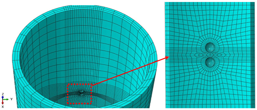
The finite element model of double pits in casing inner surface.
According to the L/R ratio, five finite element models are established, which are specifically L/R = 3.0, 2.5, 2.2, 2.0, 1.0. The casing internal pressure is 10 MPa in all cases. In order to compare with double pits, the numerical calculation was performed on single pit as well.
Simulation results and discussion
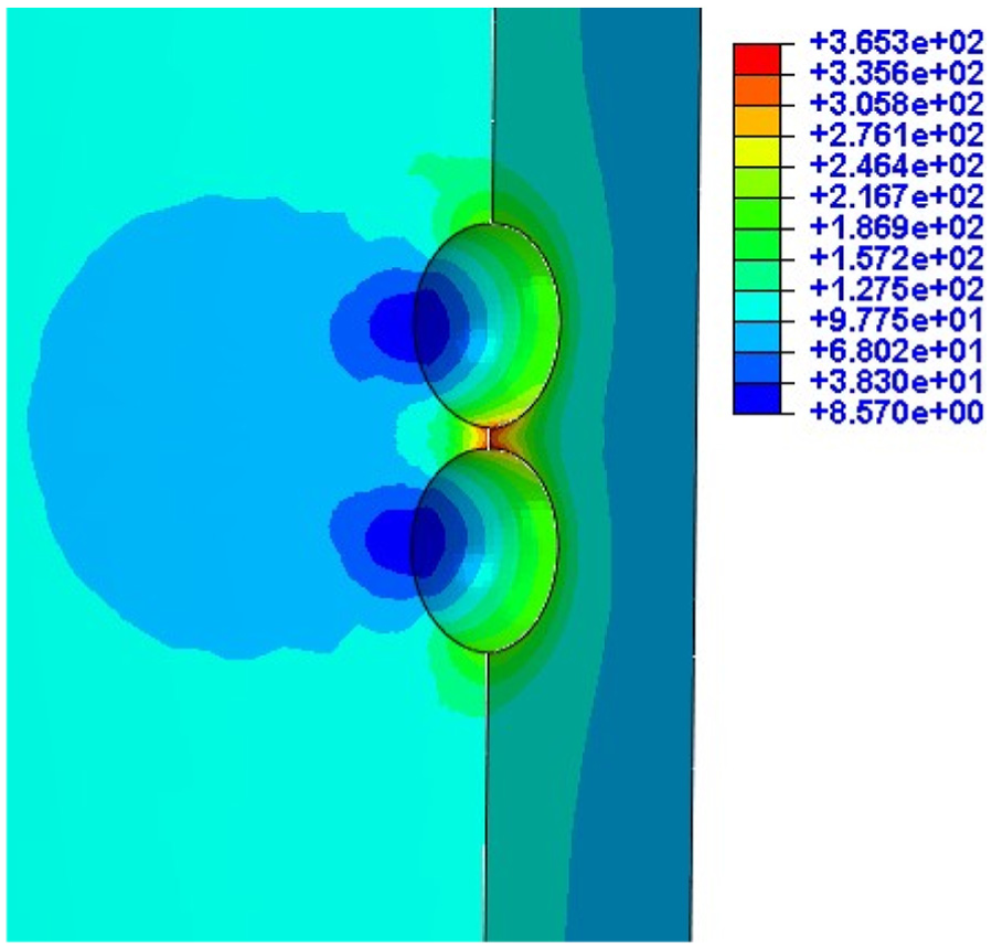
The stress contour plot of a single pit is shown in Figure 3. The von Mises stress in remote area is about 100 MPa, and the maximum stress appearing at the pit bottom is about 200 MPa (parallel to the casing axial). The SCF is approximately equal to 2.0, which is in accordance with analytical model. 9 The stress contour plot of double pits is shown in Figure 4. The maximum stress appears at the inner edges between the two pits.

Stress contour plot of a single pit.

Stress contour plot of double pits.
The stress distributions around the double pits with different pits distance are shown in Figures 5–8. These figures explicated the cross section along the axis of casing and cutting through the center of pit. When L/R = 3.0 (Figure 5), the SCF is 2.37 (237 MPa/100 MPa), which is approximately equal to the analytical solution of 2.0. When L/R = 2.5 (Figure 6), the SCF increases to 2.69 (269 MPa/100 MPa); then, when L/R = 2.2 (Figure 7), the SCF is up to 3.65 (365 MPa/100 MPa). However, the SCF decreases to 2.92 (292 MPa/100 MPa), under the condition of L/R = 1.0 (Figure 8).

Cross section stress contour plot of double pits (L/R = 3.0).

Cross section stress contour plot of double pits (L/R = 2.5).
Cross section stress contour plot of double pits (L/R = 2.2).

Cross section stress contour plot of double pits (L/R = 1.0).
Set the midpoint between the two pits as the origin, upward is positive, downward is negative, and extract the node data from the FEA simulation results along with the cross profile (white dash line in Figure 5). The SCFs of all simulation cases are shown in Figure 9. When L/R = 3.0, SCF at the outer edge is 2.03, at the inner edge is 2.36, at the pits bottom is 1.88, and at origin is 1.54. When L/R = 2.5, the SCF at the outer edge is 2.5, at the inner edge is 2. 68, at the pits bottom is 1.91, and at the origin is 2.14. When L/R = 2.2, the SCF at the outer edge is 2.09, at the inner edge is 3.65, at the pits bottom is 1.97, and at the origin is 3.25. When L/R = 2.0, where the two hemisphere pits are tangent, the SCF at the inner edge (the same as the origin) is up to 5.60; at the outer edge and pits bottom, it is still close to 2.0. When L/R = 1.0, the maximum SCF decreased rapidly compared to L/R = 2.0; the SCF at the intersection edge is 2.92 and at the outer edge and the pits bottom is about 2.0.
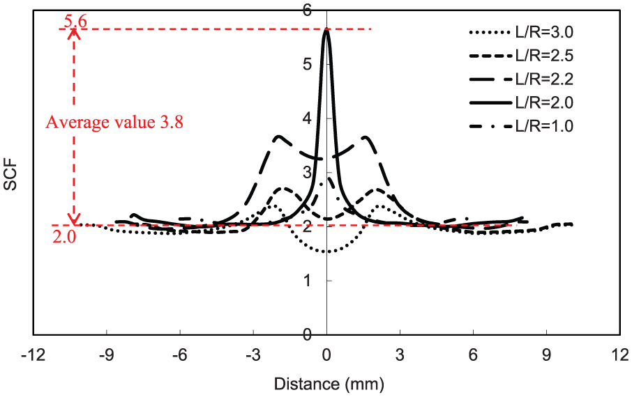
The cross section SCF distribution under different L/R values.
The SCFs changing with L/R at different locations (outer edge, inner edge, and the pits bottom) are shown in Figure 10. In the process of L/R decreasing from 3.0 to 0 (two pits are overlapped, single pit actually), the SCFs at the pits outer edge and the bottom basically keep around 2.0. However, the SCFs at the inner edge are changed significantly. Before the two pits are tangent, the SCFs increase with decrease in L/R; the maximum SCF appeared at where the two pits are exactly tangent; then, the SCFs decrease with the center distance until the two pits overlapped each other (single pit), where the SCF is roughly equal to 2.0.

The SCF changes with pits distance.
Casing strength degradation caused by the double pits stress concentration
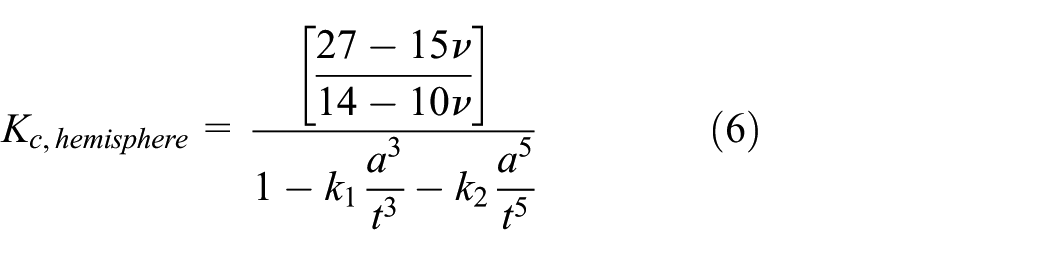
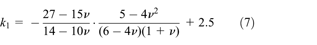
Pits formed in casing inner surface will change stress distribution near the pits and affect the strength of casing. The stress concentration enhancing effect caused by double pits needs to be considered in the downhole casing strength design. The distance of the double pits will change along with the corrosion proceeding. The maximum SCF only appears at the second of the two pits are touching. Neither the basic SCF = 2.0 nor maximum SCF = 5.6 is proper to be used as a correction factor. Therefore, the average SCF value of 3.8 (Figure 9) is recommended to modify the SCF analytical model in view of the whole corrosion process. The stress concentration strengthening correction factor of double pits in analytic expression is

When pitting corrosion occurs in the downhole casing or tubing, the modified model of the SCF is 1.9. The modified SCF calculation model is

where

where
Given the diameter of the corrosion pits is 9 mm (casing type: API 9-5/8″ (244.5 mm) × 11.99 mm, American Petroleum Institute Standard [API]), the modified SCF changes with the depth of corrosion pits is shown in Figure 11.

Modified SCF changes with the depth of corrosion pits (a = 4.5 mm).
The SCF caused by double corrosion pits can be applied to evaluate the internal pressure strength reduction of casing. Using the modified SCF of
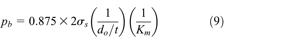
Taking casing API 9-5/8-N80 as an example, the outer diameter is 244.5 mm, thicknesses are 7.92, 10.03, and 11.99 mm, respectively, and the yield strength is 552 MPa; suppose the opening diameter of corrosion pit in pipe wall is 6 mm, the modified SCF and the casing internal pressure strength change with an increase in the depth of corrosion pit as shown in Figures 12 and 13, respectively.

Relationship between pit depth and SCF.

Relationship between the pit depth and burst pressure.
The above results show that the degree of stress concentration intensifies with an increase in the pit depth. When the depth of pit reaches half of wall thickness, the SCF factor increases faster (Figure 12). Simultaneously, the casing strength degrades significantly (Figure 13). The more the stress concentration, the more serious casing strength reduction is. In the corrosion tubing design and safety assessment, the influence of double pits stress concentration should be emphasized.
Conclusion
Stress concentration increased by double pits in a curved casing inner surface is studied using the FEA software ABAQUS. The 3D finite element models are established according to the different L/R.
The simulation results show that the double pits stress concentration behaviors in a curved surface are different from that of in a flat plate. Higher SCF values will be obtained in curved surface.
Stress concentration strengthening effect in the inner edges of double pits is more serious than that of in the pits bottom and outer edges. The degree of strengthen is related to the ratio of L/R. Before the two pits are tangent, the SCF increased with decrease in L/R; the maximum SCF appeared at where the two pits are exactly tangent; then, the SCF decreased with the two pits’ distance.
A correction factor of 1.9 was recommended in the curved inner surface double pits SCF predict model. The SCF caused by double corrosion pits is successfully applied to estimate internal pressure strength reduction of casing.
It needs to stress that stress concentration caused by double or multiple pits is not properly evaluated by the absolute distance of the two pits (B31G standard recommendation). Both of the pits size and the pits distance should be considered.
Footnotes
Academic Editor: Filippo Berto
Declaration of conflicting interests
The author(s) declared no potential conflicts of interest with respect to the research, authorship, and/or publication of this article.
Funding
The author(s) disclosed receipt of the following financial support for the research, authorship, and/or publication of this article: This work was financially supported by the National Natural Science Foundation of China (Grant Nos 51504267 and 51521063).