
Abstract
This study aims to investigate the characteristics of adaptability to stratum for thrust system in tunneling machines in composite stratum. Initially, variation coefficient thrust model has been constructed on the basis of a mechanical model. By analyzing the variation coefficient thrust model, the variation coefficient surface can be discovered. Second, by analyzing the relationship between spaces of variation coefficient surface and adaptability to compound ground, the variation coefficient surface family which indicates the adaptive ability to stratum conditions for pushing system has been discovered. Eventually, applying variation coefficient adaptability model to the driving system of shield machine in engineering applications, adaptability for two layouts with the same number of hydraulic cylinders in thrust system has been discussed in detail through comparison of numerical analysis and simulation in ADAMS. The results could provide theoretical foundation and support for the design of an adaptability thrust system under composite stratum.
Introduction
Earth pressure balance (EPB) tunneling machines have increased in frequency in recent years. 1 Compared to its other applications, EPB tunneling is mostly used in rock masses, particularly when preliminary investigations detect the presence of substances, such as asbestos and harmful or explosive gases, which threaten the health and safety of workers. EPB tunneling can be regarded as the most commonly used mechanized tunneling technology. 2 Figure 1 shows a simplified diagram of an EPB shield machine. In the tunneling process, rotating cutters fixed on the cutterhead excavate the soil, which, in turn, passes into a pressurized head chamber; the whole machine is then pushed by hydraulic cylinders with a thrust system that applies pressure on the segments.3,4 A screw conveyor removes the excavated soil from the head chamber. Among the three principal subsystems—cutting system, thrust system, and lining system—the thrust system plays the most important role in the shield machine. The thrust system propels the machine forward during tunneling and controls the position of the main machine to ensure that the machine can advance along the expected path while constructing the planned tunnel line. 5 Successful tunneling construction relies mainly on the design of the driving system used. 6

EPB tunneling machine.
In the anisotropy of excavation interface rocks, however, the inconsistencies of resistance surrounding the machine and its own weight create a complicated working situation. Under such special conditions, the offset load on segments would be easily generated. Consequently, problems caused by meandering routes, ground subsidence, and machine failure would be more likely to occur. Therefore, analyzing and designing thrust systems are of primary importance. Successful tunneling construction relies mainly on the design of the driving system used.
Generally, the hydraulic cylinders of thrust system in tunneling machine are evenly arranged equidistant along the circumference inside the shell. The amount of jacks is completed depending on the tunnel diameters and the geological conditions. For the most current driving system, all cylinders in engineering applications are divided into four groups, called as four-group system. This four-group system is designed to simplify the complex control of tunnel boring machine (TBM). But offset load on segments is easily generated in four-group system under composite stratum. 7 Nonspacing system may be more complicated, but it can provide a more even thrust force on segments and reduce the offset load if we have a reliable theory of driving system. The lesser the offset load on segments, the lesser the damages of installed segments, and it can improve the leak proofness and security of tunnel. However, certain conditions must be considered in a nonequidistant driving system; these conditions include nonhomogeneous oil, significant changes in the direction of the load on the machine body, and overweight cutterhead.
Studies have shown that there may be different deformation characteristics and natural frequencies in different driving system configurations that have the same number of hydraulic cylinders in the single stratum.8–10 In Deng et al., 11 the spatial force ellipse transmission characteristics have been researched. Although deformation characteristics for driving system under mixed ground in Deng 12 has been discussed, few studies have been carried out on the adaptability to stratum of thrust systems with various arrangements in composite strata.
This article first presents the mechanical model for pushing system in tunneling machine. Then, based on the mechanical model, variation coefficient (CV) surface has been discovered. Finally, applying CV surface into the propelling system in an engineering application, geological adaptive ability for different layout kinds of driving systems has been discussed. The result could provide a theoretical foundation and support for the design of a new driving system in shield tunneling machines under special conditions.
Construction of adaptability factor model for thrust system based on mechanical model
In accordance with Zhang et al. 13 as shown in Figure 2, hydraulic cylinders of propelling mechanism are laid out in the circular direction of the shield. The circular center of the pushing hydraulic cylinders layout is regarded as the coordinate origin where the z-axis paralleling to the center line of the main machine and being opposite to the direction of shield advancing, the y-axis perpendicular to the z-axis, upward to the ground. The x-axis is determined by the right-hand rule and then a Cartesian coordinate system is built up. In Figure 2, Fz is the resultant resistance in the direction of z-axis; Mx and My are the drags in the x and y directions, respectively; Fi (i = 1, 2,…, N) is the thrust force of the i jack in propelling system, and the system has N jacks.

Mechanical model of propelling system.
As shown in Figure 2, the force equilibrium equations are as follows
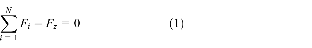


where (xi, yi) represent the layout coordinates of ith hydraulic cylinder in thrust system.
In order to apply evenly forces on rear segments, the following function that should obtain minimum value is presented

where
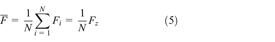
where N is the total number of jacks of the pushing system.
When the value of

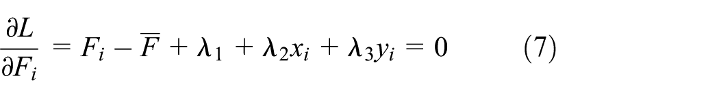
The partial differential form for equation (6) can be obtained
Combining equations (1)–(3) and (7), the following matrix function can be obtained

Supposing the left inverse matrix for the coefficient matrix in equation (8) has been worked out, the following equation can be obtained

where

is the inverse matrix of

Based on the spatial ellipse force transmission law for propelling system, 11 the optimization arrangement for thrust system has been researched 13 in single ground. While in tunneling construction engineering, there does not exist pure single stratum, and the drag force Fz and resistive moments Mx and My often change in specific ranges which can be deduced from given geological conditions. The tunneling machine is advanced by the hydraulic cylinders’ applied forces being equal to Fi on the rear segments. Equation (9) manifests that when the external loads Fz, My, and Mx vary under compound ground, all forces Fi would follow change under the given arrangement parameters of pushing system. The corresponding relationship between the external loads Fz, My, and Mx and all forces Fi for jacks in propelling system by the coefficient matrix in equation (9) can be obtained. However, the coefficient matrix in equation (9) is determined by the layout of all hydraulic cylinders in driving system. That is to say, while all spatial locations (xi, yi) (i = 1, 2,…, N) for jacks have been fixed, the one-to-one mapping between the external loads and all forces for jacks has been defined. As we known, the more even forces, the more likely are the rear segments to be protected against compression. 14 If the wider the spread of all thrust forces, the greater the values for forces applied by hydraulic cylinders. Hence, the CV for all forces applied by jacks would be introduced to measure the dispersion of all forces Fi, and the value of CV can be obtained by equation (10)

where CV denotes variation coefficient of thrust for all jacks.
The change in CV reflects the adaptive ability for thrust system under mixed ground where the specific mechanical parameters cannot be obtained, while the ranges of the external loads can be gained from the given geological conditions. Therefore, being given all parameters for tunneling geological and structural parameters, all CV should be a series of continuous values.
Characteristics analysis of CV for different kinds of driving systems
According to equation (9), the following equation can be derived
As the following equation is a true statement,

the following equation can be obtained

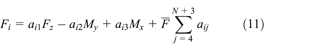
Substituting equation (13) into equation (11), the simplified equation (14) can be obtained

Substituting equation (14) into equation (10), the following equation can be obtained

Then, the expanded equation for equation (15) can be obtained

From equation (16), the following expanded equation can be obtained
After some Fz and CV values being given, the rotating movement of coordinate axis can be obtained through the following equations

where

When the value of CV is given, three eigenvalues j, k, and l for the matrix P can be obtained in equation (18), and the norm quadratic form of equation (18) can be expressed as follows

Obviously, the sign of one eigenvalue must be different from others in equation (19) and only then the shape of some spatial surface would be determined by equation (19). That is to say, the shape for spatial surface based on equation (16) should be the same as the one for equation (19). Therefore, the shape for spatial surface relied on equation (16) by all external loads Mx, My, and Fz as shown in Figure 3. Then, given a series of CV values, a lot of concentric space curved surfaces have been obtained.

CV surface for thrust system.
Case comparison studies
As shown in Figure 4, the basic structure parameters for a shield machine with a diameter of 6.18 m are r = 2.85 m, N = 24, and the maximum unitary thrust for hydraulic cylinder in driving system is 1500 kN. The stroke of cylinders for the whole propelling system is 2100 mm. The EPB shield machine has been used to excavate one tunnel in Beijing.
EPB shield machine with a diameter of 6.28 m.
As shown in Figure 5, on ground of geological conditions, pushing system 1, where all hydraulic cylinders are distributed unevenly, has been applied in the Beijing subway tunnel. In the system, all cylinders can be operated individually, and the pressure and the displacement for each hydraulic cylinder can be regulated independently. And in general, all jacks have been divided into four groups which can be controlled only through displacement and stress of hydraulic cylinders. Depending on unchanging of quantity and parameters for jacks in pushing system, system 2 has been proposed, as shown in Figure 6. According to Tang et al., 10 phase angle can be used as a parameter to define the location of hydraulic cylinder in thrust system. Therefore, all phase angles of hydraulic cylinders in two kinds of driving systems have been listed in Table 1.

Layout of driving system 1.
Layout of driving system 2.
Phase angles for two driving systems.

Inserting all phase angles listed in Table 1 into equation (17), three CV surfaces (CV = 0.03, 0.06, 0.09) for two systems can be drawn in Figure 7. From Figure 7, it can be seen that for any kind of layout, all CV surfaces have the same center axis. And the center axis for any kind of arrangement system would be through the origin of spatial coordinate. The space surrounded by CV surface increases with the increase in CV values. For any kind of determined layout system, the surface for any given CV value could be obtained. Consequently, the CV surface can be used to evaluate the performance of arrangement thrust system; in other words, the surface can be used in designing and choosing a certain propelling system. The use of CV surface will be discussed in the following section.

CV surface family for two driving systems.
Supposing the EPB shield machine with a diameter of 6.28 m would work under special conditions where ranges of Mx, My, and Fz are −955 to −854 kN m, −5708 to −5525 kN m, and 9850–10,000 kN, respectively. Under such conditions, which is the better one in system 1 and system 2? The choice should be on the basis of CV analysis.
Numerical analysis
If CV value for the elected system is <0.08 under the given geological conditions, inserting all phase angles shown in Table 1 and CV = 0.08 into equation (17), Figure 8 can be represented. As shown in Figure 8, the space surrounded by CV surface for system 2 contains ranges of external loads that are far from the one for system 1. It suggests that all CV values for the system 2 under the given conditions are smaller than the limit of 0.08. While CV values for system 1 are much >0.08, and it indicates that system 2 has more adaptive ability than system 1 under such above-mentioned conditions. Hence, system 2 should be preferred under such environment geology.
CV = 0.08 surfaces for two driving systems.
Simulation in ADAMS
Based on all phase angles of jacks, the virtual prototypes for systems 1 and 2 have been built in ADAMS, as shown in Figures 5 and 6. According to the given above-mentioned conditions, external loads for the two systems have been shown in Figure 9 by computer simulations where simulated loads are all in the above-mentioned ranges. The comparison of thrust of the third jack in systems 1 and 2 has been shown in Figures 10 and 11, respectively. These two figures manifest simulation results are coincident with the theory analysis ones, and results in simulation for two systems should be valid. At the same time, CV values for the two driving systems can be obtained by 24 jacks’ thrusts from simulation, as shown in Figures 12 and 13. All CV values for system 1 are much >0.08 in Figure 12, while values for system 2 are <0.08 in Figure 13. And all data in these two figures have been verified using the numerical analysis results in Figure 8.

External loads for two thrust systems.

Comparison of thrust for the third jack in system 1.

Comparison of thrust for the third jack in system 2.

CV values for system 1 in ADAMS.

CV values for system 2 in ADAMS.
Through the preceding analysis of comparison of engineering application for two systems, the following statements can be obtained:
With the same quantity and specifications for hydraulic cylinder, different systems would have different CV surface families that indicate the adaptive ability of one system in mixed ground.
All centric axes for CV surface families should be through the origin of spatial coordinate, and the space surrounded by CV surface is becoming greater with the increase in CV values.
The simulated values in ADAMS almost equal to the numerical values verify the CV surface model.
By setting the limit of CV value, its surface can be used to design and choose a suitable thrust system under given geological conditions.
Conclusion
This article presents a mechanical model for propelling mechanism in shield machine under complex strata. Based on the mechanical model and analysis of properties of CV thrust model, CV surface for thrust system has been discovered. By applying CV surface model to practical driving system in real engineering projects, the adaptive ability for propelling system has been investigated in detail. The following conclusions can be drawn based on this study on adaptability to stratum characteristics for thrust system under composite stratum:
With the same number of hydraulic cylinders, different arrangement thrust systems have different CV surface families which indicate the adaptive ability of driving system under composite stratum.
For a certain layout of thrust system, the space surrounded by a CV surface is growing greater with the increase in CV values.
By analyzing the relationship between a setting CV surface and the ranges of external net forces, the better layout of pushing system can be preferred.
Footnotes
Acknowledgements
The authors thank Yuanyuan Li Qingshang Tan and Zhurong Yin for their valuable advises which help to perform the analysis.
Academic Editor: Jiin-Yuh Jang
Declaration of conflicting interests
The author(s) declared no potential conflicts of interest with respect to the research, authorship, and/or publication of this article.
Funding
The author(s) disclosed receipt of the following financial support for the research, authorship, and/or publication of this article: This research is sponsored by the Hunan Province Science and Technology Plan Projects (no. 2015JC3110), the Key Laboratory of Road Construction Technology and Equipment (Chang’an University; no. 310825161108), and the Hunan University of Science and Technology PhD Research Foundation (no. E51387).