
Abstract
The nano quadrotor is a nonlinear multi-input and multi-output system with strong coupling, which causes difficulties in control law design. In order to achieve a favorable performance, an extended state observer–based nonlinear cascade proportional–integral–derivative controller is proposed in this article. First, the nano quadrotor platform is built, and the dynamic model is established. Second, a novel and practical measuring method is given to obtain model parameters. Then, based on the active disturbance rejection control method, the design procedure of the extended state observer–based nonlinear cascade proportional–integral–derivative controller is presented. In the developed controller, a tracking differentiator is involved to extract the signals of gyroscope, and extended state observer is used to estimate the disturbance. To obtain a better performance of tracking differentiator and extended state observer, a systematic parameter-tuning method is studied. Finally, simulation results are given to demonstrate the efficiency of the proposed controller.
Keywords
Introduction
The nano quadrotor is usually categorized as a type of light rotary wing unmanned aerial vehicle (UAV), which has quickly emerged in recent years. For its application in research, education and military, nano quadrotor has drawn increasing attention among scholars and geeks.1,2 Except the advantages of common quadrotors, such as vertical takeoff and landing (VTOL) and hover above target, 3 nano quadrotor can operate in more confined spaces, do more difficult maneuver, and have a better safety. 2 Therefore, nano quadrotor has many applications in military and civil use, such as reconnaissance, rescue, and so on.
The above unique features of the nano quadrotor are mainly related to its small scale (around
Except the difficulties in modeling, the quadrotor is a classical underactuated system with 6 degrees of freedom (DOFs) but only four inputs, and the dynamics of quadrotor are coupled for different channels, 13 which makes it difficult to control. Over the decades, many control strategies have been proposed to stabilize the quadrotor. Proportional–integral–derivative (PID) controller is a classical and widely used control strategy, and many PID control schemes have been designed and applied for quadrotor.14–16 However, based on the theory that “using error to overcome error,” 17 conventional PID controller has the disadvantages in overshooting and fast response. An almost globally stabilizing nonlinear proportional–integral–derivative (NPID) was developed by Su et al., 18 which is more effective and robust than conventional PID. A decentralized proportional integral derivative neural network (PIDNN) control scheme is designed to solve the nonlinearity in quadrotor, and the connective weights of the PIDNN are trained online, which shows the controller has a good adaptability. 21 In order to response faster to the input instruction, angular velocity can be controlled in inner loop of PID controller, which is known as cascade proportional–integral–derivative (CPID). 20 CPID has a good damping characteristic and a simple structure, but its setting time may be long. In degrade, the disturbance always exits, which will degrade the performance of the controller. In order to tackle the disturbance and uncertainty, a disturbance observer was designed to provide efficient estimation of the unknown compounded disturbance,22,23 and adaptive control was applied to achieve a better robustness.24–27 From the basic principle of classical PID, the active disturbance rejection controller (ADRC) has been proposed, 17 which consists of tracking differentiator (TD), extended state observer (ESO), and NPID. TD can deal with the conflict between the overshot and rapidity and has an excellent performance in filtering. ESO can estimate the unmodeled dynamics and the unknown disturbances, which can decouple the system. By utilizing the nonlinear feedback, the setting time is short. The ADRC is applied in quadrotor by Liu et al., 28 and comparing with the CPID, the output with ADRC has no oscillation and has a small overshoot. The NPID in ADRC can be chosen in different forms for control needs and control precision, and the difficulty in parameter tuning is different among the forms. 29 Since the ESO can decouple the quadrotor, the controller design can only consider the decoupling system. 30
The controller performance depends on not only the structure of controller but also the parameters of controller. In classical PID, the parameters are mostly tuned by experience. By combining the PID with intelligent control,31,32 the difficulty in parameter tuning can be overcome. However, the intelligent control is hard to be realized in embedded system 33 . By classifying the control objects in timescale, ADRC can settle this problem well. 17 Control objects in similar timescales can share one set of control parameters, which enables the advent of unified parameter-tuning theory. Each parameter in ADRC was analyzed in MATLAB to seek rule of confirming parameters. 34 A systematic parameter-tuning scheme was given in Liu and Shao 35 and applied in asynchronous motor. Considering the similarity of a class of systems, a computation method of timescale in a second-order system was given, and the feasibility of a class of systems using the same ADRC was verified. 36 The controller scaling, parameterizations and optimizations were presented in Gao, 37 and a controller tuning method in frequency domains was summarized. When the parameters are well tuned, the controller can be efficient and has a good antidisturbance performance.
Motivated by the above studies, an extended state observer–based nonlinear cascade proportional–integral–derivative (ENCPID) controller is proposed in this article, which has several modifications listed as follows. The first modification is combining the nonlinear cascade proportional–integral–derivative (NCPID) with the ESO and TD. By changing the NPID in ADRC with NCPID, the dynamics of response will be faster. The second modification is using TD to filter the signal of gyroscope, and prediction is introduced to compensate for the phrase loss. The third is a systematic parameter-tuning procedure that is given based on the previous tuning methods.
This article is organized as follows: First, nano quadrotor platform (NQP) is introduced, and the dynamic model of the nano quadrotor is given. Second, the proposed ENCPID is designed, and a procedure of parameters turning is presented. Finally, a series of simulation results and conclusions are given in the last section.
Platform design and modeling
The self-designed NQP is shown in Figure 1, which consists of the nano quadrotor, the remote control, the ultra wide band (UWB) location system, and the ground station. The nano quadrotor can operate on remote control mode or autonomous mode. In remote control mode, the nano quadrotor receives command from a six-channel remote control and adjusts its flight attitude in real time. In autonomous mode, a preset flight path is designed on ground station and then the quadrotor will track the path autonomously. In both modes, the real-time attitude and position information are displayed on ground station and recorded synchronously for further analysis.

The self-designed NQP.
The nano quadrotor
The nano quadrotor includes a flight control board, four coreless motors, a lithium battery, and a protective cage. The flight control board is shown in Figure 2, which comprises a nanoprocessor, an inertial measurement unit (IMU), a wireless module interface, and a reserved interface for first-person view (FPV) camera, UWB location system or global positioning system (GPS) module. The nanoprocessor onboard is STM32F405RGT6, with a frequency of 168 MHz, a build-in float point unit (FPU), and a special digital signal processing (DSP) library. An InvenSense IMU MPU9150 is integrated in the center of the board, which contains a tri-axis gyroscope, a tri-axis accelerometer, and a tri-axis magnetometer. Comparing with the separation scheme such as MPU6050 + HMC5883, the MPU9150 has a better coaxality. The wireless interface is connected to a 2.4-GHz Zigbee, and the antenna is printed on the circus board to reduce the weight. The effective communication distance is 150 m, which is enough for the nano quadrotor working in sight. In order to determinate the position, an reserved interface can be connected to one of the three modules: UWB tag, FPV camera, and GPS. The UWB tag and FPV camera are used in GPS-denied area, such as indoor environment, and GPS is equipped in open field.

The flight control board.
For the balance of torque and mass, four coreless motors are fixed on the flight control board symmetrically, and plastic sleeves are involved to link them. The motors are driven by SI2302 MOSFET to provide lift, and 55-mm rotor is chosen to match the motor. Instead of step-less speed adjustment, more simple and practical pulse width modulation (PWM) control is adopted. To ensure an enough smoothness and accuracy of control, the motor speed range is divided into 500 levels. A 350-mA h lithium battery is fixed below the flight control board to supply electric power. The voltage monitor is designed to avoid over discharging, and max flight time is up to about 7 min. The nano quadrotor is surrounded by a resilient protection cage, which can prevent the damage of collision. The total weight of the nano quadrotor is 43.60 g (without position sensor), and the mass distribution is shown in Figure 3.
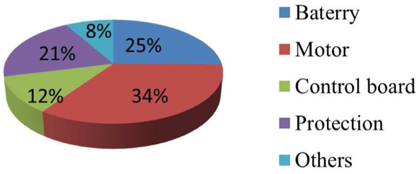
The mass distribution of the nano quadrotor.
System dynamic modeling
To simplify the modeling, some assumptions are made: 38
The nano quadrotor is a rigid body where vibration and deformation are ignored.
The shape and the distribution of mass are symmetrical.
The form and the parameter of the dynamic model are time invariant.
The gyroscopic moment of the rotor is ignored.
The nano quadrotor is a 6-degree-of-freedom (DOF) rigid body, including 3-DOF translation and 3-DOF rotation. In order to describe the movement, the body frame (denoted as

The frame of nano quadrotor.
The rotation matrix and transformation matrix from


where
According to the Newton–Euler equation, we have 39

where
The forces on the nano quadrotor are the gravity, the lift of rotor, and the air drag. The gravity is

where g is the gravitational acceleration and
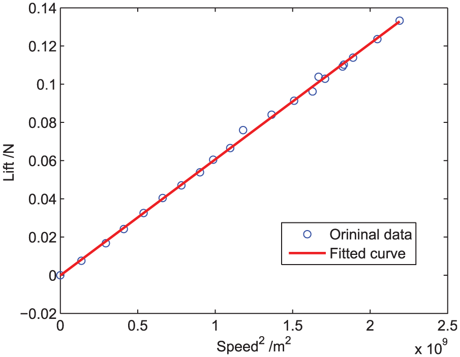
The lift relates to the air density, the aerodynamic shape, and the speed of the rotor.
40
Define

where
The air drag is given by

where

The pitching moment is caused by the lift difference of rotors 1 and 2 and rotors 3 and 4, which can be calculated as follows

where l is the half distance of the adjacent motors.
Similarly, the rolling moment is

The yawing moment is determined by the twisting moment difference of rotors 1 and 3 and rotors 2 and 4. The twisting moment of each rotor is written as

where
Thus, the yawing moment is

Let U be the control input, and combining equations (5), (8)–(11), we have

Define
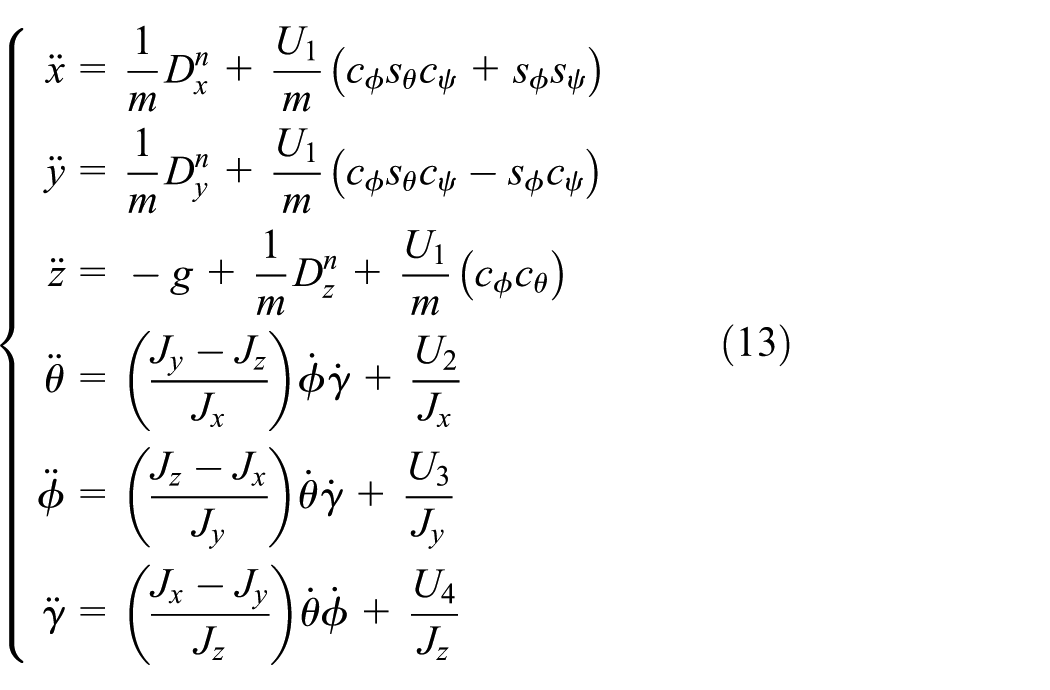
Parameter measurement
The mathematic model of the NQP has been derived in equation (13). However, some of the parameters are still unknown. In this section, some experiments are designed to obtain the model parameter.
The nano quadrotor is an irregular-shaped body. Hence, the moment of inertia cannot be directly calculated. In order to measure the parameter, a trifilar torsional pendulum (TTP) is designed, which is shown in Figure 5.

Experiment setup for TTP.
In Figure 5, the level meter is used to ensure that the upper and lower disks are in horizontal level, and a smooth link is beneath the lower disk to avoid the side rotation. The structure of the three-line pendulum is shown in Figure 6, where R is the distance between suspension point and disk center, L is the length of suspension line, and

The structure of TTP.
The moment of inertia around the pendulum axis is given by 41

where
The mass and the length can be measured precisely by electronic balance and vernier caliper, respectively. However, the precision of

The periodic signal with time.
In order to get rid of the noise of magnetometer in Figure 7, a median filter is used, and the result is shown in Figure 8.

The periodic signal with time after filter.
A binary conversion is made according to the mean of the signal, and the periods are the difference of the time of the rising edges as shown in Figure 9. The mean period in Figure 10 is the Tp.
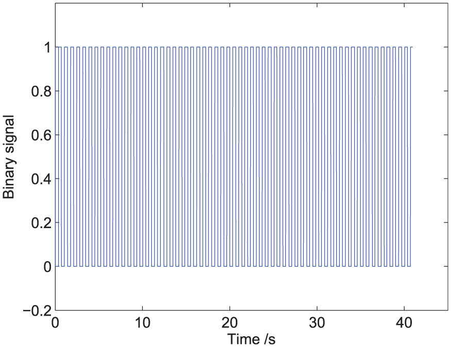
The binarization of periodic signal.
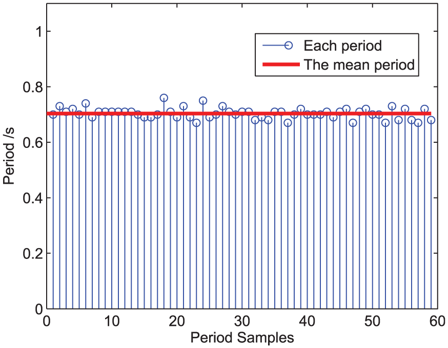
The mean period of the signal.
The center of gravity (CG) can be obtained by suspending the nano quadrotor. 42 When the quadrotor is fixed on the lower disk, the CG should be right above the center of the disk.
The measurement of
Fix one nano quadrotor on the center of lower disk horizontal.
Start measuring the periodic signal (here the magnetic of x-axis is chosen).
Give an initial pendulum angle and record the signal for enough time.
Intercept reposeful record to obtain
Fix two nano quadrotors, and repeat steps 2 to 4 to obtain
Calculate the moment of inertia of the nano quadrotor and disk around z-axis as


where the
In Figure 11, the
The
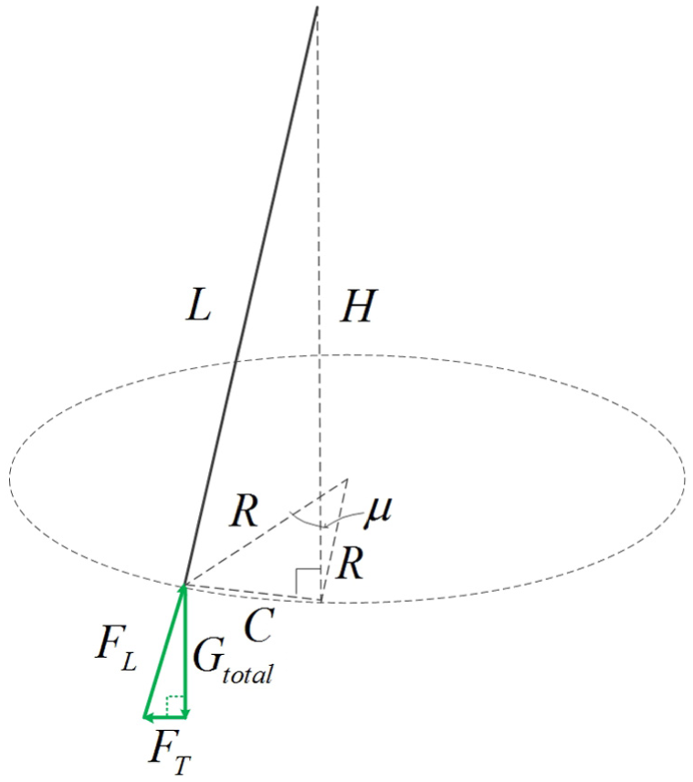
Force analysis of TTP.
According to the similarity of force triangular and geometric triangular, and considering of the lift of rotor, the proportion relationship exists

where
The pendulum angle

And the twisting torque can be calculated as follows

In Figure 13, the

The
So far, all the model parameters of the nano quadrotor are obtained and listed in Table 1.
The model parameters of the nano quadrotor.

Controller design
The principle of ENCPID
Considering the parameter uncertainties and unmodeled disturbances in equation (13), the principle of ENCPID controller is presented in this section.
The framework of the ENCPID flight control system is shown in Figure 14, where

The framework of ENCPID flight control system.

The structure of ENCPID.
Take pitch channel as an example and the three parts in Figure 15 are designed as follows:
1. The TD can extract the signal and its differential efficiently. Considering that the gyro measured value contains noise and its differential will amplify the noise, the TD is designed as
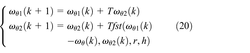
where

2. ESO can estimate the states and the disturbance. In equation (13), take pitch channel as example, the relation between

where
In order to compensate for the disturbance

where
Using

where
3. The NCPID of pitch channel contains two loops,

The diagram of NCPID.
Considering that the differential of Euler angles can be obtained directly from the IMU rather than making forward difference, the controller is designed as

where

It is noted that

Parameters tuning
In this section, the influence of each controller part related to performance is given. Then, the tuning procedure is presented in detail. Finally, a general turning method is summarized.
The parameters of each controller part are of crucial importance to the performance. According to separation principle, 43 the parameters are independent among TD, ESO, and NCPID, which means that the parameters in the three modules can be turned individually.
TD gives the estimate deferential signals
The relation between r and transient dynamics

where
In equation (29), if we need

where
The parameters in TD are highly correlated with the input signal. The fast change dynamic signal requires increasing r and a small phase loss, and much noisy measurement needs a good filter property. Relation equations of parameters of input signals and TD are given by 44
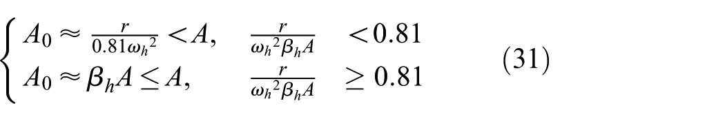
where
In equation (31), when
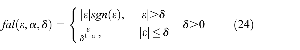
Increasing

where
b is the compensation coefficient, and from equation (13),
The convergence and stability of ESO are mainly influenced by
Some rules are given as follows: 35
In linear ESO, when the control period T is settled,
In nonlinear ESO,
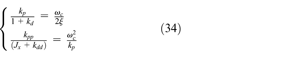
In equation (28), the closed-loop transform function is a second-order system. The adjust time is

where
First, the expected performance index
If
Simulations
In this section, extensive simulations are presented to evaluate the proposed ENCPID. By applying the tuning method in the previous section, the parameters of ENCPID are given in Table 2.
The parameters of improved ADRC.
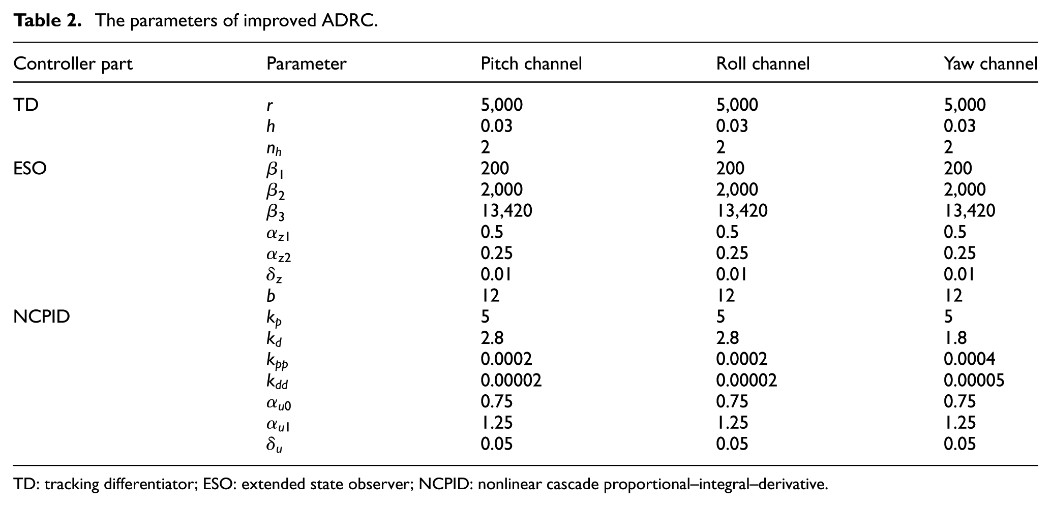
TD: tracking differentiator; ESO: extended state observer; NCPID: nonlinear cascade proportional–integral–derivative.
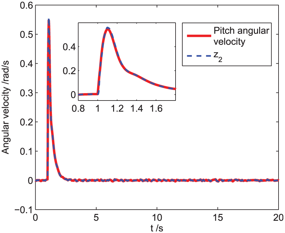
Taking pitch channel as example to demonstrate the performance of TD and ESO, the simulation results are shown in Figures 17–23.

The estimation of angular velocity.

The estimation of angular acceleration.

The output of TD in different

The output of controller.

The estimation of pitch.
The estimation of pitch derivative.

The estimation of disturbance.
As shown in Figures 17 and 18, the outputs of TD can track the angular velocity and angular acceleration well, and the noise in IMU data is suppressed effectively. In Figure 19, the relation between prediction steps
In order to demonstrate the performance of the proposed ENCPID, the simulation results of ADRC, CPID, and ENCPID are shown in Figures 24–26. The adjusting time is ENCPID ≈ ADRC > CPID, which is because of the nonlinear function

The step response of pitch channel.

The step response of roll channel.

The step response of yaw channel.
Conclusion
In this article, the attitude control of the NQP using the ENCPID is studied. A nano quadrotor platform, including the nano quadrotor, the remote, and the ground station, is designed first. For further research, the mathematical model is deduced, and its parameters are measured precisely by several experiments. Then, the ENCPID controller is proposed, and a systematic parameter-tuning method is summarized. Finally, the simulation results show that the ENCPID has a rapid response over the adjusting time and a good noise rejection capability. The nano quadrotor platform built in this article has a great potential in deeper research, and some application, such as trajectory control and autonomous cooperative control, will be studied in the future.
Footnotes
Academic Editor: Chenguang Yang
Declaration of conflicting interests
The author(s) declared no potential conflicts of interest with respect to the research, authorship, and/or publication of this article.
Funding
The author(s) disclosed receipt of the following financial support for the research, authorship, and/or publication of this article: This paper was support by National Natural Science Foundation of China (Grant No. 61573184), Specialized Research Fund for the Doctoral Program of Higher Education (Grant No. 20133218110013), the 333 high-level personnel training project of Jiangsu Province (Grant No. BRA2015359) and the Fundamental Research Funds for the Central Universities (Grant No. NE2016101).