
Abstract
Due to different inertia, sediment particles stop following the trails of water elements during the flow passage of a centrifugal pump. In a dredge pump, deviation characteristics of sediment particles from surrounding fluid are still not crystal clear. Apparently, the deviation makes sediment particles attacking the inner wall and causes wear and tear. In addition, the deviation would also decrease the pump efficiency. In order to understand the motion of the sediment particles and their deviation characteristics inside a dredge pump, authors built a Lagrangian numerical model based on particle’s kinematic balance equations, and then verified it through a rotating platform. The influential factors of the sediment particle motion, such as the rotation speed, as well as the diameter and density of sediment particles, were investigated. Finally, a conclusion is obtained that says if blade profiles are close to the relative trajectory of a particle, this particle will cause minimized wear to the blade wall.
Introduction
Copping with the booming business of land reclamation from the sea, navigation channel construction and maintenance, and sediment deportation from reservoirs and lakes, dredge manufacturing industry is developing remarkably fast. Centrifugal dredge pumps are often used to transport dredged sediment. 1 Dredger pumps often suffer severe wear damage of internal surfaces after a certain operation period of time, especially for transporting sand and gravel, which will reduce the dredge pump efficiency and effective head, as well as the reliability and stability of pump, and eventually shorten the life of the pump. The most affected parts are the impeller, volute, suction tube, and shaft seals. 2 Seal failure would yield serious pollution of oil spills of runner, bearing and other components, and also increase noise. The location of wear depends on contact of particles with internal surface of pump which is again decided by hydraulic conditions, the composition, and type of solids carried inside the pump. Working life of a dredge pump can be realized only if the parameters chosen for the pump elements, sediment, and transport conditions will provide economic transport with minimal wear. Hence, research on the route of coarse granular sediment particles in centrifugal dredge pumps is meaningful.
There are many studies on wear and abrasion of internal surface of pump,3–11 but only few focus on the motion of particles in centrifugal dredge pumps. Wilson et al. 1 discussed the effect of solid concentration on deposit velocity and fully stratification of coarse-particle transport. Paone et al. 12 used particle image displacement velocimetry to measure the flow field in a diffuser of a centrifugal pump with clear plexiglas casing and impeller. Experiments were performed with water as the fluid and metallic-coated micro-spheres (diameter: 4 µm, density: 2.6 g/cm3) as seed particles. They identified the blade wake path. Dong et al.13,14 used particle displacement velocimetry (PDV) technique to visualize the flow within the volute of a centrifugal pump, while neutrally buoyant particles of 30 µm mean diameter were used as seed. Cader et al. 15 conducted laser Doppler anemometry (LDA) measurements in a centrifugal dredge pump at a concentration of 1%. Micron size tracers and 0.8 mm glass beads were also used. Mehta et al. 16 obtained the velocities of sediment particles in the impeller of a centrifugal dredge pump by utilizing particle image velocimetry (PIV) technique in conjunction with refractive index matching. Tests were performed in an optically clear centrifugal dredge pump at speeds of 725 and 1000 r/min using a sediment made up of sodium iodide solution as a working fluid and glass beads (mean diameter: 500 µm) as solid particles at volumetric concentrations of 1%, 2%, and 3%. In the intra-blade region of the impeller, the highest particle velocities were obtained both in the suction side of the blade and in the blade trailing edge region as the blade sweeps through and velocity magnitude increases with the increase in the pump speed. But this magnitude was less than that of circumferential velocity of the blade tip. The average particle velocities were obtained, and it was found that the average particle velocity decreases with increase in concentration. The fluctuating component of particle velocity, which is related to the fluctuation kinetic energy, was obtained. By increasing the particle concentration, fluctuation kinetic energy decreases, and the maximum fluctuation kinetic energy typically occurs on the suction side of the blade. The sediment particles are pushed on the pressure side (PS) of the blade and slide on it. This can result in frictional wear. Garman 17 applied the ultrasound technique to measure the local particle velocity within the pump using a pulsed ultrasound Doppler velocimetry (PUDV) device. In order to measure the velocity profile in the pump, he adopted a method which required performing two PUDV measurements with two different inclination angles (Doppler angles). Li et al. 18 presented an experimental investigation of the flow fields in a centrifugal pump by PIV technique with two different tracer particles, all designed for the same operating point. In order to systematically analyze the tracking characteristics of tracer particles once used in centrifugal pump by Basset–Boussinesq–Oseen (BBO) equation, aluminum powder (AP; with high density ratio and small diameter) and hollow glass spheres (HGS; with neutral density and large diameter) were selected. They found that HGS tends to conglomerate closer to the PS near the impeller outlet than AP.
Recently, Shi et al. 19 proposed a two-phase identification method based on statistics of gray-scale level and particle size for PIV image analysis. The algorithm was applied with good performance and reliability for PIV image processing of particle–fluid two-phase flow inside high-speed rotating centrifugal dredge pump.
As the pumps are commonly made of metals, the motion of particles is not visible. Even if the pump casing is made of plexiglas, the high laden sediments would make the flow opacities. With the development of computational fluid dynamics (CFD) and the improvement in performance of computers, it has been possible to use numerical simulation to study the motion of particles in centrifugal dredge pumps. Twenty years ago, CFD started to play a key role for the prediction of flow through pumps and impellers and successfully contributed to the enhancement of their design. Pagalthivarthi et al. 20 presented a quasi three-dimensional (3D) approach to predict particulate phase motion and concentration in an arbitrary radial section of a centrifugal dredge pump. The concentration distribution is obtained by invoking the convection–diffusion equation. The governing partial differential equation is cast into a weak Galerkin finite element form. The system of algebraic equations is solved by a Newton–Raphson scheme via a frontal solver. An iterative solution scheme is employed to alternate between the fields of particle motion and concentration. Hofstra et al. 21 presented results of numerical and experimental studies of the interaction of particles and the boundary layers inside the pump impeller. Their calculations predicted that particle trajectories could be modified at low angles of attack, and at higher angles, particles would impact the blade. Pagalthivarthi et al. 22 presented a numerical prediction of erosion wear trends in a centrifugal pump casing pumping dilute slurries. They utilized Discrete Phase Model (DPM) in FLUENT 6.1 to obtain dilute slurry flow field through the pump casing employing two-way coupling, and k − ε model for turbulence. Kumar 23 studied 3D fluid flow behavior of centrifugal dredge pump using commercial CFD code FLUENT at design and off-design conditions. Recently, Shen et al. 24 simulated the internal flow field of screw centrifugal pump by CFD code using the DPM based on Euler–Lagrange method when transmission medium was solid–liquid two-phase flow with large-size particles. The result showed that the low-density fine particles trajectory were longer, more collision times with flow passage components, more energy loss, and the erosion parts were relatively uniform, but particles which were of large-size diameter and high density had big collision angles with the surface of impeller and volute. Up to now, CFD approach has been extensively used in centrifugal pumps for performance prediction at design and off-design conditions, parametric study, cavitation analysis, analysis of interaction effects in different components, prediction of axial thrust, study of pump performance in impeller mode, diffuser pump analysis, and so on. Unsteady Reynolds-averaged Navier–Stokes (URANS) equations together with two-equation k − ε turbulence model were found to be appropriate to get a reasonable estimation of the general performance of centrifugal pump, from an engineering point of view, with typical errors less than 10% compared with experimental data. Impeller and diffuser flows have been extensively studied, and volute flow study has appeared as an interesting research. 25
In this article, the dilute solid–liquid two-phase flow in a centrifugal dredge pump is simulated both experimentally and numerically, so that characteristics of flow field and sediment motion in a simplified two-dimensional (2D) model are analyzed using numerical simulations and physical tests. Achieving this purpose, methods to calculate the segregation angles of solid particles in the swirling flow and design of dredge pump, and measurements against abrasion are proposed.
Materials and methods
Dynamics of granular sediment particles in dredge pump
In curvilinear flows, because of the density difference between the particle and the fluid, solid particles are hard to follow the path of micro-fluid. It, therefore, will be relatively deviated from micro fluid. Generally speaking,
When the density of particles is less than the fluid, such as a bubble, the particle surface pressure difference is greater than the centripetal force required by those particles following the fluid motion curvatures, the particles will go in a manner of a small curvature radius in the direction of migration. On the contrary, when the particle density is greater, particles will go in a manner of a large curvature radius in the direction of migration.
The migration of solid particles will lead to redistribution of their concentration. Solid particles in the migration process usually collide with the boundary, thus cause the energy loss and the abrasion of the boundary. Therefore, the migration of solid particles in the rotating flow is a kind of dominated phenomena in dredge pumps.
The migration of sediment particles through the main flow curve depends on particle density, shape, diameter, concentration, pump rotating speed, and so on. 26
Simplified 2D physical model and numerical model
The flow field in the dredge pump is typically 3D with high degree of complexity, unsuitable for exploring the law of trajectories of solid particles. Therefore, for simplicity, a 2D simplified model was designed to capture the important characteristics of sediment particle motion in the swirling flow. As shown in Figure 1, the model contains a cylindrical barrel rotating with a vertical axis in a constant angular velocity, which is filled with water. The water inside the barrel was gradually accelerated under drive of inner sidewall of the barrel, and ultimately a stable 2D swirling flow field was formulated. The particles motion behaved as “bed load,” rather than “suspended load,” that is, moved as contact load. Supposing the flow ran in an ideal fluid, the water would be still in a relative coordinate system of rotation. Furthermore, if there are not many particles existing in the running water, then the particle collision would not happen and particle motion would not affect flow motion. From both numerical analysis and model test point of views, this is a simple idealized model which is very easy to implement and verify. Based on the model, migration characteristics of sediment particles in different curvature radii and angular velocities of flow curves were numerically and experimentally investigated for different solid particle sizes, densities, and shapes.

2D simplified test model.
In order to compare with physical model tests, Hong et al. 27 also once built a numerical model with Lagrange method based on particle’s kinematic balance equations as follows.
In the vertical
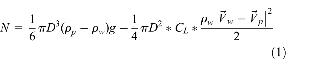
where N is the supporting force of the bottom, D is the size of the particle, ρp is the density of the particle, ρω is the density of the water, CL is the lift coefficient,
In the horizontal

where m is the mass of the particle, λ is the dynamic friction coefficient, CD is the drag coefficient, ω is the angular velocity of the reference system, and
From the above, the particle’s dynamic equation could be shown as

These equations could be solved by iterative method when the particle’s size, density, initial location, and velocity were given. In solving the integral equation, the Runga–Kutta method was used. The influence factors of the sediment particle motion, such as the rotation speed of the cylindrical container, as well as the diameter and density of the sediment particles, were investigated. In this article, discussion and analysis of particle’s deviation characteristics were presented based on numerical results.
Verification of numerical model
Numerical simulation results were verified by 12 sets of experimental tests. In the experiment, the trajectory of the spherical particles was taken from the video images of a high-speed camera, and then the velocity distribution of particles was obtained by analyzing the trajectory.
For example, Figures 2 and 3 depict that trajectories and particle deviation angles (the angle between movement directions of the particle and the local fluid) of a 10-mm particle through numerical and experimental investigations, respectively. From both the trajectory and deviation angle, their trends in numerical and experimental investigations are consistent and similar. Errors of calculating the diversion angles may be mainly resulted from the selection of relevant parameters in the numerical model, such as dynamic friction coefficient of the particle on the sidewall surface and the lift coefficient. The increment of difference in Figure 2 occurred mainly because errors accumulated in every step when calculated the diversion angles.

Comparison of experimental and calculated trajectories of particle.

Comparison of experimental and calculated diversion angles of particle.
Results and discussions
Effect of initial entry position
Five different initial positions were assumed for a particle. Figure 4 says that the absolute rotation trajectory of the end of all curves coincides with each other. In other words, the absolute trajectories of the particle are identical except for a slightly different initial part. It depicts that the motion of this particle is independent of its initial state and irrelevant to its motion history. Furthermore, the movement of particles could be divided into two stages of adjustment and full development. Different initial positions have different adjustment processes, but the motion of the particle immediately changes afterward and proceeds in a manner of history independence, that is, the process of development and change of the radius vector had nothing to do with the historical process and is only related to properties of particles, characteristics of flow field, and time.

Trajectories of particles with different initial positions.
Effect of entry particle density
As represented in Figure 5, the greater density of particle causes shorter route of the particle motion and a faster collision with the sidewall. This means higher density makes particle more difficult to follow liquid flow and then more easy to be separated. Obviously, the absolute velocity of particles is less than the local velocity of fluid, so a higher density results in a greater velocity difference between the particle and local fluid.

Relative trajectory of particles with different densities.
Figure 6 depicts that a greater density leads to a greater deviation angle. The variation of deviation angle can be divided into three stages: a rapid rise, a fast descent, and a slow descant. The greater density results in a greater magnitude in both rapid rise and decline stages. In the slow-declining stage, the deviation angle decreases steadily while radius increases. Afterward, the greater density brings a bigger speed of the decrement again.

Deviation angle varies with radius and density.
Taking the max(β) of the relative density ρp/ρw = 1.1 as a benchmark, the five curves in Figure 6 were unified as to have the same maximum and then replotted in Figure 7, where

Similarity of Cb against time in the first two stages.
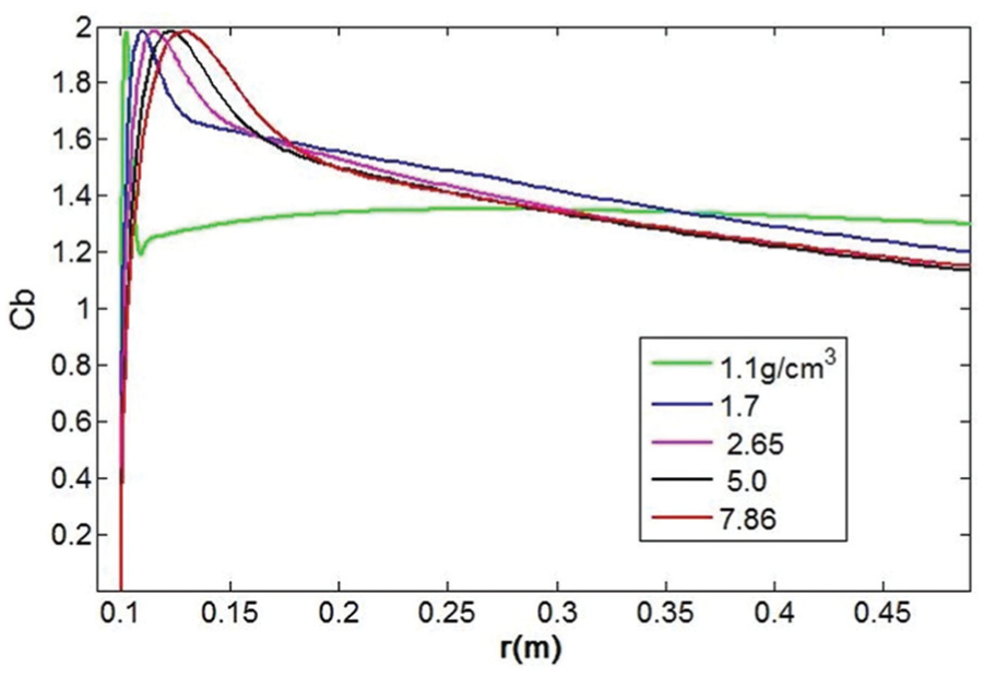
Similarity of Cb against radius in the last stage.
Regarding the above analysis on density effect, it can be found that when the relative density exceeds a certain value, the adjusting time is same for particles with different densities. Using the time to obtain the radius of different particle, the angular deviation angle of the particle at arbitrary vector can be obtained according to the diagram of angular separation between the radius vector and maximum deviation angle varying with density.
Effect of entry particle size
Figure 9 depicts that a bigger particle size results in a longer distance to arrive the sidewall in a relative motion. The densities of these particles were the same. So, bigger particles are considered to be following worse in short.

Relative trajectory of particles with different sizes.
As it can be seen from the variation process of radius shown in Figure 10, different sizes of particle have experienced different time durations to reach the sidewall. The time from the smallest to the largest particle is in the order of 10 < 5 < 2 < 20 < 1 mm. Hence, bigger particles, while less than 10 mm, result in an earlier arrival to the sidewall.

Radius variation of particles with different diameters.
Figure 11(a) depicts that a larger particle size leads to a sharper raise in the relative velocity, that is, a bigger velocity difference between the particle and local fluid results in worse ability to follow the fluid. The solid lines shown in Figure 11(b) denote the absolute velocity of the particles, while the dotted lines represent the local fluid velocity of the fluid. Obviously, the absolute velocity of the particles is less than the local velocity of the fluid, and the deviation is larger as the particle size increases.

(a) Relative velocity and (b) absolute velocity of particles with different diameters.
The interpretation of radial migration velocity with the change of particle diameter is so complicated that it can be divided into three stages: the initial rising, the falling, and the second rising stages. At the rising stage, bigger particles not only go faster but also the speed rises higher. During the falling stage, the larger particle size results in a more rapid fall. During the second rising stage, however, the larger particle size for those of 1–5 mm leads to a higher radial migration velocity, while for particle size of 5–10 mm, it is more complex that the radial migration velocity has two intersection points. Thus, the time to hit the sidewall is almost same for these two particle sizes. Apparently, if the barrel size increased, 10-mm particles would experience relatively less time to hit the sidewall; however, it seems that 20-mm particles are especially unstable to migrate, so that the migration velocity steadily grows after experiencing several radial velocity fluctuations. Such a process should be associated with the variation of Reynolds number, because Re and CD are also varying remarkably and affect the particle’s motion significantly. For particles bigger than 20 cm, CD will experience a notable change and then leads to particle’s kinematic fluctuation.
The variation of deviation angle may be divided into three stages: rapid-rising, sharp-declining, and slow-declining stages as shown in Figure 12. A larger particle size causes a greater magnitude of rapid rising stage and a greater magnitude of the rapid decline stage. Except for the particle of 20-mm diameter having significant fluctuations, remaining particles have a very low velocity in slow-declining stage. It can be regarded that the separation angle uniformly decreases with the increase in radius. Furthermore, a bigger particle size causes a smaller speed of the decrement.
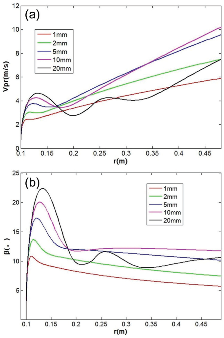
(a) Radial migration velocity and (b) deviation angle of particles with different diameters.
Effect of impeller rotation speed
Figure 13 shows that trajectories of same particles are basically same under different rotating speeds. Among them, only a very low-speed one is slightly different, and its basic reason might lie in the fact that the boundary layer around the particle separates when the rotational speed creates a high Reynolds number Re (generally faster to reach between 2 × 10⁴ and 2 × 10⁵). The wake region behind the particle reaches the maximum, and the drag coefficient, CD, would remain basically unchanged.

(a) Absolute and (b) relative trajectories of solid particles at different speeds.
Relative speed divided by the rotational speed as indicated in Figure 14 has been found to be dependent on the particle radius for different speed conditions. Therefore, for the same radius, the relative velocity of particles should be proportional to the rotational speed.

Spatial similarity of relative velocity at different rotational speeds.
A greater rotational speed means a greater absolute speed of the particle. Also, the absolute velocity or rotational speed basically depends only on the radius, that is, the absolute velocity is proportional to the rotational speed. So, after the initial period, the absolute speed can be expressed as

where Kvpa is an unknown constant which has nothing to do with the rotational speed, 0.9866 in this study, which is so close to one that the absolute velocity of particles is substantially proportional to the flow velocity of fluid near the particle.
Characteristics of particle collision to the sidewalls
Figure 15 shows that when the particle meets the sidewall, it continues to repeat the process of collision, rebound, and collision, and so the velocity of particle motion gradually decreases. While stop time of particle motion is tf = 3.9058 s from numerical simulation, it is statistically within 3.6591–3.9058 s, 16 collisions happen. A close-up at the right part of Figure 15 shows that the repeated collision process of particles clearly evidences. Repeated collisions of particles impact should obviously be an important reason for the sidewall abrasion. In addition, the elastic collision coefficient is assumed to be 0.9, namely, high rigidity of wall causes high collision force, such that the abrasive should be obvious. If the wall rigidity reduces, it would shorten the process of particle collision, the collision force would then be smaller, and the abrasion would also greatly reduce.
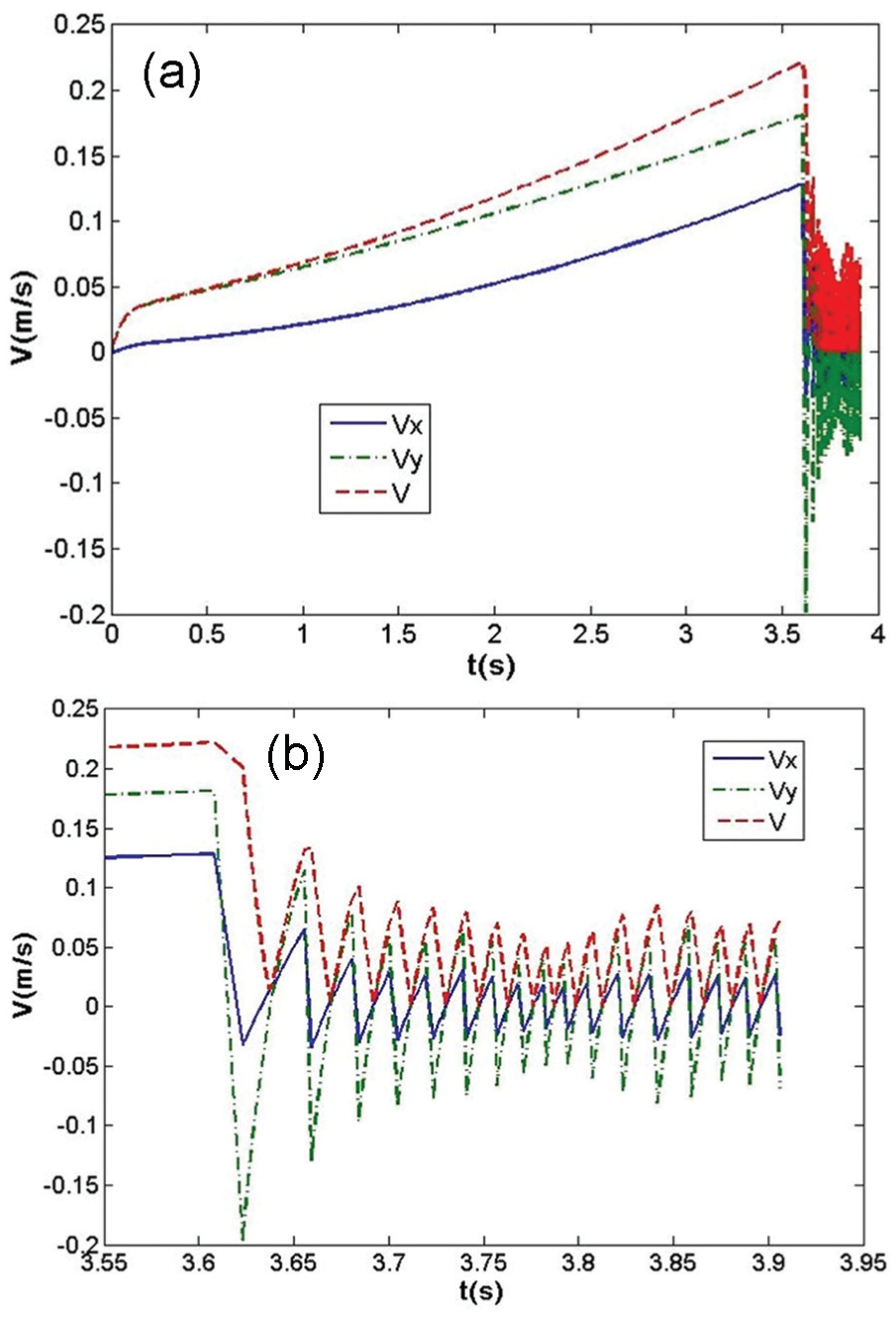
Variation of relative velocity of particles with time in relative rotation coordinate system.
General methods for anti-wear of dredge pump
Design of impeller blade wrap angle
Generally speaking, blade tail of dredge pump impeller is the worst region of erosion. According to the consequences and results, some methods may be proposed to increase the wear resistance of dredge pump.
The particle density and size are important factors influencing the route of particle motion and wrap angle, which determine the wear scope and intensity. It has been shown that the effect of initial position of a solid particle and its initial velocity on its path in curvilinear flows is almost negligible. Hence, the methods in sections “Effect of impeller rotation speed” and “Characteristics of particle collision to the sidewalls” may be directly used to estimate the movement of sediment particle in curvilinear flows. As depicted in Figure 16, under a certain speed and impeller diameter, the trajectory of a sediment particle motion is mainly decided by its equivalent diameter (specific weight: 2650 kg/m3 has been assumed). According to the path of the particle (relative to the impeller) and the relative position to trajectory of the blade profile, it can be said that
The pump impeller blade is suitable for conveying sediment particles of nearly 16 mm in diameter. As shown in Figure 17, the wrap angle of blades is package angle which basically equals to the wrap angle of particle motion trajectory. Such a diameter of sediment particles would not cause too many collisions and much wearing abrasion.
For smaller diameter of sediment particles, some particles would collide with the tail region of non-working lee surface of blades. But due to a smaller particle size, the velocity difference relative to the surrounding fluid would not be so large that the abrasion would not be very serious.
For larger diameter of sediment particles, 20 mm, some particles would collide with the tail region of working frontal surface of blades. Furthermore, due to a bigger particle size, the velocity difference relative to the surrounding fluid would be so large that the abrasion would be serious.
From section “Characteristics of particle collision to the sidewalls,” after reaching the frontal surface of the blade, particles would be discharged off along the blade surface in a manner of continuously jumping, so that a continuous process of collision is produced. Therefore, the tail end region of the blade would be the worst abrasion region, which is in agreement with the abrasion position and morphology of the impeller in actual working conditions.

Relationship between particle trajectory and blade profile.

Comparison of the relative trajectory of sediment particles of size 16 mm and the blade profile.
As a conclusion, if overall efficiency of the dredge pump is not affected and the flow ability of particles through the channel is not significantly degraded, the blade profile design should be taken into consideration of characteristic diameter of particles and their expected trajectory. Due to the slip phenomena, a suitable slip factor should also be taken into account. The wrap angle which minimizes the possibility of collision should be taken into design. At the same time, the inlet and outlet angles should also be taken as smaller as possible provided that the flow ability of particles through the channel is not significantly degraded, as well the overall efficiency of the dredge pump is not affected. Due to a 3D-complicated flow behavior inside a centrifugal impeller, the results of this study cannot completely protect the sediment particle hitting the walls but can minimize the hitting.
Design of dredge pump speed
According to wear model proposed by Benedetto Bozzini et al., 28 the wear rate is proportional to the collision particle number, particle mass, and particle relative velocity of 2.4 times square. As discussed above, the relative velocity of the particles is proportional to the rotation speed. Hence, for a fixed particle, the abrasion speed would be dramatically increased to be 5.28 times when the rotation speed raises 100%. Therefore, under normal circumstances, the design rotation speed of dredge pump should be as low as possible in order to reduce the abrasion problem caused by collisions of sediment particles.
Anti-abrasion protection using elastic material
At present, metal materials with high hardness are widely adopted as anti-abrasion protection measures. Nevertheless, because of the high hardness of such materials, rigid sediment particles collide with the material as a manner of completely elastic collision. Therefore, collisions also increase while improving the ability of the abrasion resistance of materials.
As aforesaid, a single particle experiences a sequence of elastic collisions with the wall surface of blade with high frequency. Although the relative velocity decreases while the number of collisions increases, abrasion speed produced by the collisions would reduce.
If the flexible macromolecule material (e.g. polyurethane) is used as a protective lining, the impact energy would be absorbed through the deformation of flexible materials, so that the presence of the protective layer will significantly reduce the number of repeated particle collisions with blades. Hence, the anti-abrasion performance of dredge pump will significantly improve.
Conclusion
Based on numerical and physical investigation by a simplified 2D dilute solid–liquid two-phase flow model, the following conclusion would be summarized:
Both the trajectory and deviation angle of particles are consistent in numerical and experimental investigations.
The motion of solid particle is independent of its initial state in a swirling flow and irrelevant to its motion history.
Solid densities have a significant impact on particle’s motion, and heavier ones seem to be separated more easily. But it seems having no effects on the time needed for reaching max(β).
Bigger particles have greater relative velocities and deviation angles when the diameter is not big enough to notably affect CD. But this relationship can be used in many field processes since particles are normally smaller in two-phase flow.
For various angular velocities of curved flow, particle’s traveling trajectories, and variation process of its deviation angle, are all the same, but the relative and absolute velocity are both proportional to the angular velocity.
When the particle meets the sidewall, it continues to repeat the process of collision, rebound, and collision, which will induce wear and tear of the sidewall.
An impeller blade shape can be constructed by the trajectories of sediment particle calculated in this study combined with a suitable slip factor. The design wrap angle should guarantee to minimize the possibility of collisions. As the incident angle is sufficiently small and pump head is satisfied, this study suggests that the blade angle at inlet and outlet is as small as possible.
Also, the design rotation speed of dredge pump should be as low as possible in order to reduce the abrasion problem caused by collisions of sediment particles.
Due to a 3D-complicated flow behavior inside a centrifugal impeller, the results of this study cannot completely protect the sediment particle hitting the walls but can minimize the hitting.
Nevertheless, flexible macromolecule material (e.g. polyurethane) for anti-erosion of dredge pump is proposed to be a protective lining, rather than rigid material like high chromium cast iron.
Footnotes
Acknowledgements
The authors thank the editing effort made by Miss Azam Dolatshah.
Academic Editor: Takahiro Tsukahara
Declaration of conflicting interests
The author(s) declared no potential conflicts of interest with respect to the research, authorship, and/or publication of this article.
Funding
The author(s) disclosed receipt of the following financial support for the research, authorship, and/or publication of this article: This work was financially supported by the grant from the National Basic Research program of China (no. 2013CB036103).