
Abstract
This study systematically investigates the impact of impeller arrangements on the mixing efficiency of gangue particles and slurry through experimental validation and numerical simulations. The research focuses on the interplay between impeller quantity, positional layout, and rotational speed to optimize particle-fluid homogeneity. Results demonstrate that increasing the stirring speed from 100 to 200 rpm enhances the average mixing concentration in the central region by 38.5%, confirming the critical role of rotational velocity in accelerating gangue-slurry integration. Notably, a single centrally positioned impeller operating at 200 rpm achieves mixing uniformity comparable to a dual-impeller system while reducing cycle time by 21.2%. These findings redefine optimal impeller configurations for industrial applications, emphasizing efficiency and energy conservation.
Keywords
Introduction
Gangue represents a crucial mineral resource, and the utilization of coal gangue-fly ash cemented backfill mining has emerged as a pivotal direction for green development in coal mines in recent years. 1 Through activation treatment, coal gangue can be transformed into a high-strength, acid- and alkali-resistant cementing agent, which can be formulated into grouting reinforcement slurries. These slurries serve to solidify pollutants, adsorb heavy metals from mine water, and enable the comprehensive utilization of both coal gangue and mine water. This practice holds significant practical importance for enhancing the containment and preservation of groundwater resources, as well as for ensuring engineering stability and safety.2–4
The agitation process preceding the grouting of gangue slurries is vital for ensuring a uniform distribution of particle concentration, which directly impacts the grouting effect, material utilization rate, and ultimately, the quality and safety of the engineering works. 5 During agitation, the rotational speed, position, and quantity of impellers exert notable influences on the agitation outcomes. Consequently, studying the particle concentration distribution of gangue slurries under varying impeller positions holds profound theoretical and practical significance.
Recent advances in impeller design optimization have demonstrated significant impacts on solid-liquid suspension efficiency. Jirout and Jiroutová highlighted that hydrofoil impellers enhance energy efficiency through optimized pumping and circulation effects, with performance highly dependent on geometric configuration. 6 Meng et al.’s CFD simulations further compared hydrodynamic characteristics of hydrofoil impellers, pitched blade turbines, and grid paddles in circular tanks, confirming distinct flow patterns induced by different impeller types. 7 For non-Newtonian systems, Hinge et al. systematically proved that hydrofoil impellers outperform Rushton turbines and pitched blade designs in gas dispersion uniformity and holdup at identical power inputs, particularly under low-power conditions. 8 Moravec et al.’s axial large-blade hydrofoil variant (e.g. 4TR10) exhibited superior mixing and flocculation efficiency in wastewater treatment, generating larger aggregates with reduced unagglomerated residues, showing promise for mining slurry applications. 9
To achieve particle uniformity in slurries, integrated experimental-numerical approaches are essential. Mao et al. combined MRF and RSM models to quantify impacts of impeller diameter (400–800 mm), speed (100–300 rpm), and particle size (20–500 μm) on mixing homogeneity and power consumption.10,11 Yin et al. adopted Euler-Euler models with RNG k-ε turbulence closure to analyze solid suspension stability in baffled tanks, 12 while Ge and Zheng employed CFD-DEM to resolve particle-flow interactions in dual-impeller systems. 13 These studies underscore turbulence modulation (macro-scale transport to micro-scale eddies) as critical for slurry-particle dynamics. 16
This knowledge is crucial for engineering research in analyzing fluid-particle interactions and elucidating mechanisms governing particle concentration distribution during mixing.
This study innovatively establishes a quantitative framework to assess the mixing performance of gangue slurry by integrating a multiphase flow mixing numerical model with experimental validation. Specifically, this study quantifies the effects of impeller quantity and rotational speed on hydrodynamic interactions within slurry-particle mixtures under dynamic flow conditions. Through systematic analysis of shear force distribution, turbulent flow characteristics, and particle suspension patterns within the mixing zone, this research reveals the mechanism by which impeller configuration parameters modulate the spatial-temporal evolution of slurry concentration heterogeneity. The novelty lies in: (1) Using a multiphase flow numerical model to evaluate the mixing process of water and particles, (2) establishing design criteria linking impeller geometry-operation parameters to mixing uniformity metrics, and (3) proposing an optimized stirring protocol that provides quantifiable engineering guidance for pre-mixing operations in coal seam fracture grouting applications. The findings directly inform equipment selection and process control strategies to achieve targeted slurry rheological properties in underground mining scenarios.
Experimental plan design
The experiments used gangue particles with a density of 1.8 g/cm2, and the overall mixed slurry had a density of 1.55 g/cm2 and a stable viscosity of 0.35 Pa s. The mean particle diameter was 203.3 µm, and the particle size distribution under laser measurement is shown in Figure 1.

Particle size distribution of gangue in the slurry.
The curve in Figure 1 represents the percentage of the total volume of particles smaller than a certain particle size to the total volume of the slurry. The sharp increase indicates that the number or volume of particles in this particle size range is relatively large. The cumulative volume curve in Figure 1 reaches 50% at a particle size of 203.278 μm, that is, d50 = 203.278 μm. This value is called median diameter, which means that 50% of the particles have a diameter less than 203.278 μm. The median diameter is an important parameter that characterizes the overall coarseness of particles in the slurry. The experimental group architecture specifically incorporates three stirrers with varying impeller heights as variable factors, as illustrated in Figure 2(a). This configuration is designed to systematically investigate the multidimensional impacts of impeller height-a critical operational parameter-on both the experimental process and outcome metrics. All trials were conducted under standardized conditions (21°C ambient temperature), with the stirring apparatus configured as follows: motor rated at 200 W power output, operating within 220 V electrical supply parameters with a 1.2 A nominal current draw, and capable of achieving 1400 rpm maximum rotation speed. The impeller parameters in the mixing device are shown in Figure 2(b).

Display the relevant status of the position and parameters of the impeller: (a) placement position of impeller and(b) impeller shape and parameters.
In the experimental design, the dimensions of the mixing tank (diameter: 50 cm, height: 58 cm) were determined based on a geometric scaling ratio of 1:10 relative to industrial backfill mixing tanks and the impeller design specifications from the Buertai Coal Mine grouting equipment. Then, a specially designed impeller type was selected and developed based on the physical properties of the slurry and particles, such as density, particle size, viscosity, etc.; Finally, regarding the variable position of the impeller, three different horizontal planes were set vertically, 3 cm from the bottom of the single impeller, 25 cm from the top of the single impeller, and 3 and 25 cm from the distribution of the two impellers. The horizontal position was fixed at the center of the mixing tank.
Specific experimental steps
Specific experimental steps:
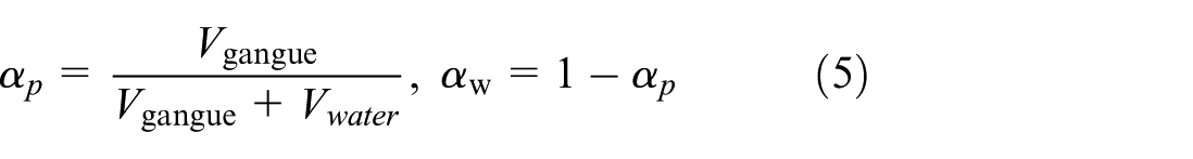
(1) After mixing the slurry and coal gangue particles in a ratio of 60% (the volume ratio of particles to water was measured experimentally, such as 40% sand by volume for a phase fraction of 0.4, avoiding ambiguity caused by particle size dispersion in mass based definitions), the mixture was allowed to settle and separate into layers, and then the impeller motor was started to stir.
(2) Conduct stirring experiments at each impeller position and record parameters such as the distribution of fine particles in the stirred coal gangue.
The microscopic distribution of particle concentration and the dynamic changes in the flow field during stirring are crucial for understanding potential stirring mechanisms, optimizing stirrer design, and improving product quality. However, due to practical limitations of the experimental setup, directly observing these microscopic details may be challenging. Therefore, based on the relevant parameters of the experiment and the characteristics of the two-phase flow of water and gangue, the concentration distribution during the movement of water and gangue particles is considered. Therefore, a two-phase flow model is selected to construct the distribution and interface characteristics of particles and water in the stirring chamber. This method can provide a deeper understanding of the mixing process of particles and water under the action of impellers at the microscopic scale.
Two phase flow model and particle distribution and flow field analysis
Two phase flow governing equation
Fluid phase control equation
The fluid phase (such as slurry) during the mixing process follows basic physical laws including mass conservation, momentum conservation, and energy conservation. Therefore, the governing equations for the fluid phase generally encompass the continuity equation (mass conservation equation) and the Navier-Stokes equation (momentum conservation equation).14,15 These equations describe the flow characteristics of the fluid during the mixing process, such as the velocity field, pressure field, and so on.
The continuity equation can be expressed as equation (1).16,17

Among them, ρ is the fluid density, and
And Navier Stokes can be expressed as equation (2).

Among them, μ is the fluid viscosity, p is the pressure,
Particle phase control equation
The particle phase is subjected to forces from the fluid phase during the mixing process, and there are also interactions among particles. To describe the motion and distribution of particles, Euler-Euler models or Euler-Lagrange models are typically used.19–23 In this study, given the relatively uniform particle size distribution (mean diameter 230.3 μm), the Euler-Euler model was selected. This model treats the particle phase as a continuous medium, using parameters like volume fraction and velocity to describe particle motion and distribution.
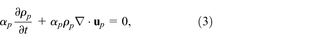
The continuity equation of particle phase is expressed as equation (3)
Among them, ρ
p
is the particle density, α
p
is the volume fraction of the particle phase, and
The momentum equation of particle phase can be expressed as equation (4).

Among them, p
p
is the pressure of the particle phase,
Therefore, by adopting the two-phase flow model (Euler-Euler) in OpenFOAM twoPhaseEulerFoam, and using the Reynolds stress term in the closed turbulence RANS equation,25,26 it is possible to more accurately simulate and analyze the particle distribution and flow pattern during the stirring process. To provide theoretical and technical support for achieving uniform transportation of slurry.
Particle distribution and flow field analysis during mixing process at different speeds and impeller positions
Perform three-dimensional numerical simulation analysis on three experimental setups in numerical analysis and verify the mesh independence of the models, as shown in Figure 3.

Establishment of the numerical model for the mixing of gangue and slurry: (a) impeller settings, (b) separation of gangue and water interface, and (c) convergence of mixing bucket grid.
Firstly, perform grid convergence analysis before computation to ensure that the grid size meets the computational requirements. Considering the bending nature of the impeller edge, an unstructured tetrahedral mesh is used to achieve a body fitted mesh at the boundary. The results obtained from three different grid sizes (0.001–0.02, 0.001–0.01, 0.001–0.005 m) have an error of less than 3% at 0.01–0.01 m, as shown in Figure 3(c), indicating that the grid meets the calculation standard. 27 Meanwhile, Figure 3(b) shows the phenomenon of interface distribution between gangue and water in multiphase flow in the initial state.
Due to the inconsistent turbulent flow states within the fluid field at varying rotational speeds, these turbulent conditions also exert a certain influence on the mixing of particles. The RNG k-ε turbulence model was selected for its capability to handle a wide range of Reynolds numbers—from the fully turbulent regime in the upper water phase (Re >10e5) to the transitional state of the mixed slurry (Re ≈ 957). Given the non-uniform turbulence conditions within the flow field at different rotational speeds, which significantly influence particle mixing, the RNG model effectively simulates the turbulent behavior of both the slurry and particle phases during impeller rotation.28,29 The time step was set according to the CFL condition to ensure a Courant number less than 1. 30 Initially, a comparison is made between experimental and numerical simulation results regarding the distribution of gangue particle phase during the mixing process, specifically when the impeller is at the bottom position, under varying rotational speeds, as illustrated in Figure 4.

Stirring process comparison between experimental and numerical simulations with a single impeller at the bottom:(a) bottom single impeller mixing test and (b) bottom impeller simulation.
Upon comparing the experimental data and numerical simulation results presented in Figure 4, it becomes evident that the mixing efficiency of the gangue particles within the slurry is significantly constrained when the impeller is positioned at the bottom of the mixing tank. Specifically, Figure 4(a) depicts an experimental scenario where little to no effective stirring of the gangue particles by the impeller is observable, indicating a minimal stirring effect from this position. Contrastingly, the numerical simulation shown in Figure 4(b) indicates that even at a rotational speed of 100 rpm, while the impeller is able to trigger localized movements in the accumulated gangue particles, its influence remains limited, resulting in unsatisfactory mixing outcomes.
As the rotational speed increases to 200 rpm, the numerical simulation reveals a noticeable improvement in mixing efficiency, particularly when examined in conjunction with the z-axis mid-section profile of the mixing tank depicted in Figure 5. The stirring efficiency is markedly higher than that at 100 rpm, yet this improvement remains localized primarily to the bottom and middle regions, failing to achieve a uniform mixture throughout the entire slurry.

The concentration of gangue particles at different times on the Z-direction monitoring surface of the bottom single impeller.
In summary, the design of a single impeller positioned at the bottom of the tank, due to its notable limitations in mixing efficiency, poses challenges in ensuring overall uniform mixing of the slurry in engineering practice. Consequently, this design may require optimization or adjustment of the stirring system configuration to enhance mixing performance in practical applications.
Further investigate the flow field distribution characteristics under the rotation of the bottom impeller, considering the influence of impeller stirring on the entire flow field, as shown in Figures 6 and 7.

Changes in velocity vectors at different time points on the y profile.

Changes in velocity vector at different times on the monitoring surface in the middle of the mixing drum.
As observed from the velocity vector changes in the y and z cross-sections under 100 and 200 rpm stirring conditions depicted in the figure, at 100 rpm, significant velocity variations are evident only at the bottom and outer edges, with no apparent velocity vectors discernible at the central rotating axis. Conversely, at 200 rpm, the scope of velocity flow across the cross-sections notably expands, accompanied by a marked increase in flow velocity compared to 100 rpm. Notably, the central rotating axis on the z-cross-section is also influenced by the impeller stirring, which is further corroborated by the gangue particle concentration distribution shown in Figures 4 and 5.
Based on this understanding, an experiment was conducted by positioning the impeller in the middle of the mixing tank to investigate its stirring effectiveness, as illustrated in Figure 8.

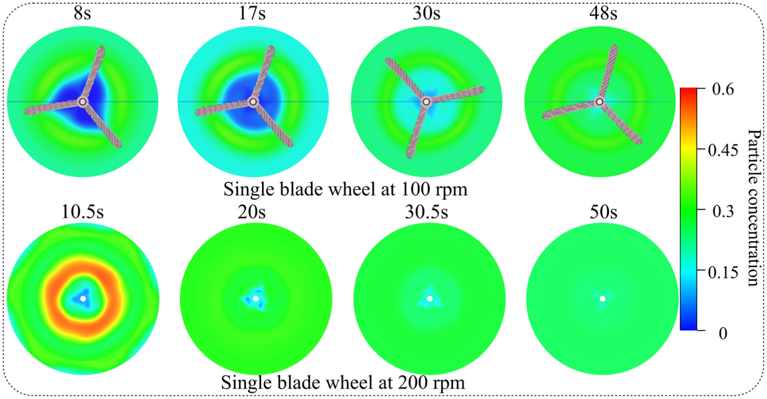
Mixing process of single blade wheel test and numerical simulation in the middle: (a) middle single impeller mixing test and (b) middle single impeller mixing simulation.
Through a meticulous comparison of the experimental results presented in Figure 8(a) at different rotation speeds (100 and 200 rpm), a clear understanding is gained regarding the crucial impact of rotation speed on mixing effectiveness. Specifically, at the lower rotation speed of 100 rpm, the stirring action is predominantly confined to the upper region of the accumulated gangue particle zone, with the particles in the lower region remaining largely unmixed, resulting in significant mixing inconsistencies. Conversely, when the rotation speed is increased to 200 rpm, a remarkable improvement in mixing is observed, as the gangue particles at the bottom are effectively agitated and suspended within the slurry, achieving a uniform particle distribution throughout the mixing tank and attaining an ideal mixing state.
To further validate these experimental observations, numerical simulations were conducted, as depicted in Figure 8(b). The 100 rpm simulation aligns well with the experimental findings, showcasing good mixing of upper particles while leaving unmixed gangue particles at the bottom of the mixing tank. In contrast, the 200 rpm simulation reveals an exceptional uniformity in the distribution of gangue particles within the mixing tank, with particles fully mixed and agitated both at the top and bottom, in perfect agreement with the experimental observations. Notably, the particle concentration distribution across the z-cross-section, as illustrated in Figure 9, visually demonstrates the substantial contribution of the central impeller operating at 200 rpm to promoting a uniform distribution of gangue particles, thereby further confirming the accuracy of the numerical simulations.

The concentration of gangue particles at different times on the Z-direction monitoring surface of the single impeller in the middle.
The high level of consistency between experiments and numerical calculations not only verifies the precision of the numerical methods employed but also underscores their reliability in characterizing the mixing process and distribution states within the mixing tank. This approach provides a solid theoretical foundation and technical support for quantitatively assessing the particle uniformity of mixed slurries, robustly demonstrating the effectiveness and practical value of computational analysis in evaluating stirring effectiveness.
Further in-depth analysis of the flow field characteristics and streamline distribution of the central impeller at different speeds, as shown in Figures 10 and 11.

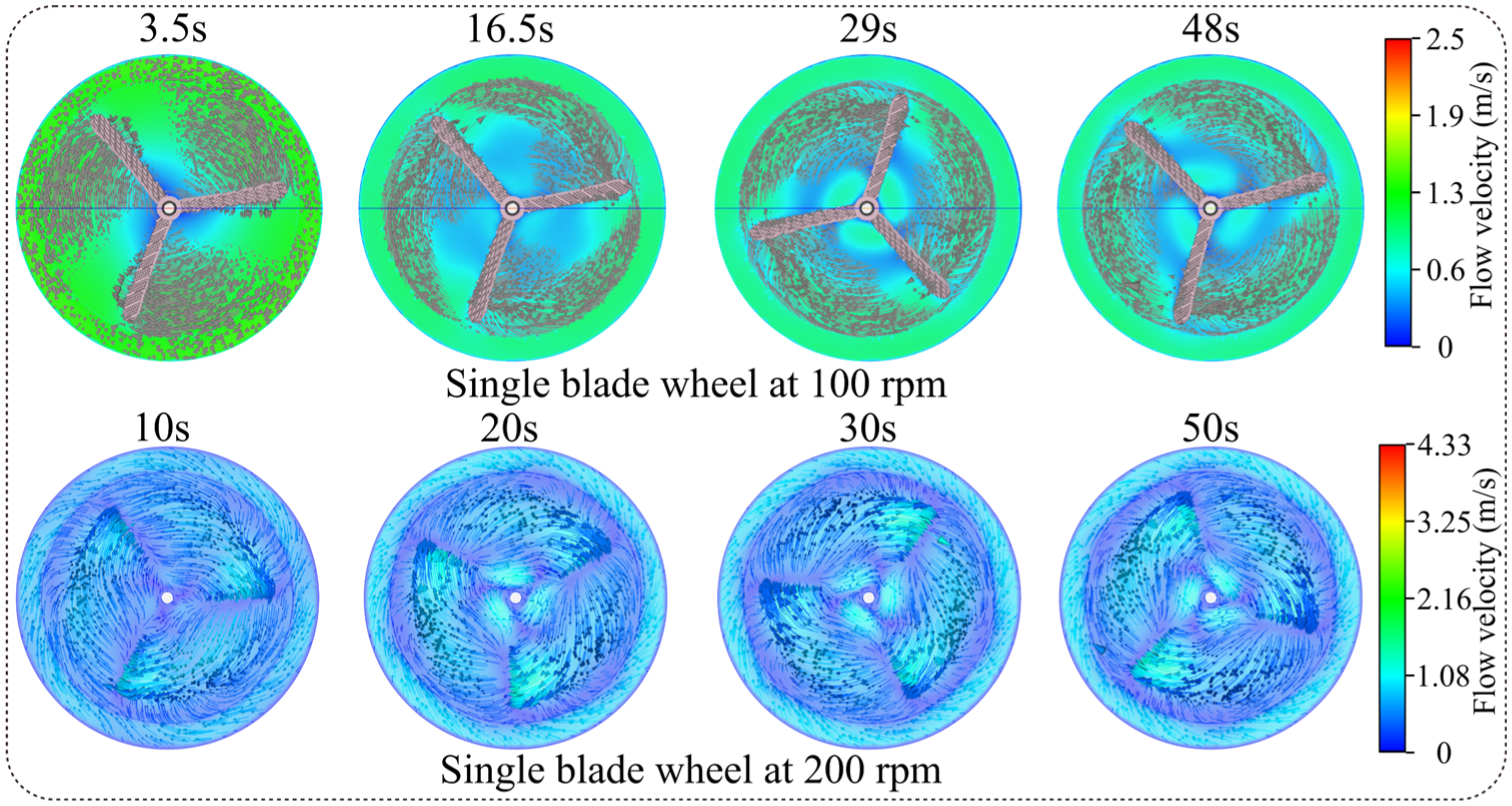
Stable flow field streamline and velocity vector variation at different times on the y-section of the middle impeller:(a) streamline and (b) single blade wheel at 200 rpm.

The variation of velocity vector at different times on the z-section of the central impeller.
In the comparative presentation of Figure 10(a), the notable alterations in the streamline distribution of the flow field upon increasing the stirring speed from 100 to 200 rpm provide profound insights into the enhancement mechanisms of mixing efficiency. Specifically, at a stirring speed of 100 rpm, the streamlines are primarily confined to the immediate vicinity of the stirring impeller, failing to effectively penetrate and cover the entire interior space of the mixing tank. This localized flow pattern restricts the uniformity and efficiency of mixing, resulting in a relatively weaker stirring effect.
In contrast, when the stirring speed is elevated to 200 rpm, the streamline distribution undergoes a fundamental transformation. The streamlines not only closely follow the impeller’s rotation but also significantly expand into every corner of the mixing tank, forming a more extensive and dense flow network. This comprehensive coverage characteristic signifies that high-speed stirring not only intensifies fluid-fluid interactions but also facilitates the thorough mixing and uniform distribution of materials within the mixing tank.
A deeper dive into the velocity vector variations along the z-axis cross-section in Figure 11 reveals that, under 200 rpm conditions, the velocity vectors exhibit higher density and stronger directionality across the cross-section, directly reflecting the intensified nature and enhanced efficiency of the stirring process. In comparison, the velocity vectors at 100 rpm appear relatively sparse and lack distinct directionality, further corroborating the limitations of its mixing performance. Furthermore, a detailed analysis of the gangue particle distribution characteristics within the dual-impeller system at varying rotation speeds, as depicted in Figure 12, offers additional insights into the intricate interplay between stirring dynamics and particle dispersion.

Mixing process of double vane wheel test and numerical simulation: (a) double blade wheel mixing test and (b) double blade wheel mixing simulation.
Upon meticulous examination of Figure 12(a), it becomes evident that the stirring process at 200 rpm achieves a near-perfect state of uniformity. This homogeneity emerges as a direct consequence of the enhanced fluid dynamic properties that manifest over time with the increase in stirring speed. The transformation signifies a marked improvement in the mixing capabilities.
When considering the comprehensive view presented in Figure 12(b), it becomes undeniable that the 200 rpm stirring speed engenders an unprecedented level of uniformity and blending throughout the entire mixing tank. Regardless of the corner within the tank, the robust driving force exerted by the dual impellers ensures that the gangue materials are thoroughly mixed and homogenized in three-dimensional space. This comprehensive and intensive mixing effect far surpasses that achievable at 100 rpm.
Moreover, the particle concentration distribution along the z-axis cross-section depicted in Figure 13 further underscores the superior uniformity achieved at 200 rpm. The concentration profile reveals a notably more even distribution, reinforcing the notion that high-speed stirring significantly enhances the mixing efficiency and homogeneity of the system.
Concentration variation of gangue particles on the z-section of the impeller.
On this basis, further analysis was conducted on the flow field characteristics under different stirring conditions of two impellers at different speeds, as shown in Figures 14 and 15.

Changes in velocity vector at different times on the y-section of the double impeller.
Changes in velocity vector at different times on the z-section of the double impeller.
In Figure 14, when the stirring speed is set at 100 rpm, a notable phenomenon emerges where the velocity vectors between the two impellers gradually overlap over time, indicating an intensified stirring effect in localized regions. However, it is crucial to observe that a significant reduction in velocity vectors forms a low-velocity zone in the axial region, which directly points to a bottleneck in mixing efficiency—this region struggles to achieve thorough material mixing and homogenization. This phenomenon is not only visually evident in the velocity vector plot but is also reinforced by the concentration distribution in Figure 13, showcasing the uneven mixing at the axial center.
In contrast, a substantial improvement is observed when the stirring speed is elevated to 200 rpm. At this speed, the velocity vectors comprehensively cover the entire stirring zone, eliminating the low-velocity zone and ensuring a uniform distribution of stirring action throughout the container. This efficient stirring pattern is clearly demonstrated in the concentration distribution map (Figure 13), validating that the coordinated work of the two impellers at 200 rpm achieves thorough material mixing, yielding superior stirring outcomes.
Further inspection of the velocity distribution along the z-axis cross-section in Figure 15 reveals that under 200 rpm conditions, the velocity vectors within the entire flow field exhibit higher uniformity and consistency, with generally higher velocity values compared to those at 100 rpm. This discovery profoundly underscores the significance of stirring speed in enhancing the dynamic characteristics of the flow field and its direct impact on mixing efficiency and quality. Consequently, it can be concluded that elevating the stirring speed to 200 rpm is a more rational and effective choice when striving for efficient and uniform mixing.
In summary, the stirring effectiveness of the impellers at 200 rpm is superior to that at 100 rpm, not only in terms of mixing uniformity but also in its ability to more efficiently facilitate material interactions and reactions, laying a solid foundation for subsequent process steps. Therefore, the achievement of comprehensive and uniform stirring within the mixing tank at 200 rpm is pivotal in enhancing mixing efficiency and product quality.
Discussion
In deeper analysis of the stirring process, agitation at 200 rpm is definitively established to enable uniform and extensive mixing within the tank. Quantitative analysis systematically examines variations in gangue particle concentrations at predefined monitoring points under different stirring speeds to refine this understanding. This comprehensive approach aims to quantitatively assess the mixing efficiency and effectiveness, providing a nuanced understanding of the process. The coordinates and locations of these monitoring points are illustrated in Figure 16.

Spatial distribution of monitoring points inside the mixing drum.
Specifically, our focus will center on agitation speed, along with the number and positioning of impellers, as core variables. By measuring the dynamic variations in gangue particle concentrations at various monitoring points under different rotational speeds, aim to construct a multidimensional evaluation system for stirring performance. This quantitative analysis not only validates the optimal stirring speed between 100 and 200 rpm but also delves into the intricate relationship between rotational speed and stirring efficacy. Ultimately, it provides robust data support and theoretical foundations for selecting the appropriate stirring process and enhancing mixing efficiency.
Firstly, Figure 17 illustrates the distribution of gangue particle concentrations at various monitoring points over time under a stirring speed of 100 rpm.

Effect of impeller state changes at different monitoring points on concentration at 100 rpm.
As shown in Figure 17, the concentration distribution of each monitoring point converges toward a specific concentration over time, approaching the experimentally determined uniform concentration value of 0.26 (which is a value obtained in the experiment). The specific phenomenon is that at 100 rpm, both the central impeller and the double impeller configuration show a trend toward a volume fraction of 0.26. For the central single impeller and double impeller settings, the recorded concentrations at point a are 0.37 and 0.43, respectively, while the recorded concentrations at point b are 0.305 and 0.285, point c are 0.31 and 0.28, point d is also 0.31 and 0.23, and point e is 0.325 and 0.28. All these values indicate that the volume fraction of particles at various positions inside the bucket during the mixing process is approaching the experimental value of 0.26. The dual blade wheel configuration shows a more pronounced effect. However, the concentration change effect of a single impeller at the bottom in the comparison chart shows a significant difference in experimental values at an average distance of 0.26 from each monitoring point. Therefore, at 100 rpm, both the single impeller and two impeller configurations in the middle are significantly better than the bottom mounted impeller design. Compared with the uniform concentration in the experiment, the error of the double blade wheel setting is only 8.1% (excluding the bottom monitoring point), indicating that the mixing is close to perfect. In contrast, the central single impeller setting showed a significant error of 21.2%. However, the central impeller configuration achieved uniform mixing in a relatively short period of time, improving mixing efficiency, which is crucial for energy conservation and efficiency improvement in engineering applications.
Building upon the insights gained at 100 rpm, a deeper analysis is now conducted on the 200 rpm rotational speed, as illustrated in Figure 18. This expanded analysis enhances comprehension of stirring dynamics and efficiency at elevated rotational speeds, providing valuable insights for optimizing industrial mixing processes.
Effect of impeller state changes at different monitoring points on concentration at 200 rpm.
In Figure 18, the temporal variations observed at various monitoring points reveal that under 200 rpm, the central single-impeller configuration rapidly achieves uniform mixing, swiftly approaching the experimental value of 0.26. While the dual-impeller setup also attains a uniform particle concentration of 0.26, it does so over a longer duration. This observation underscores the superior mixing effectiveness of the central impeller configuration at this rotational speed.
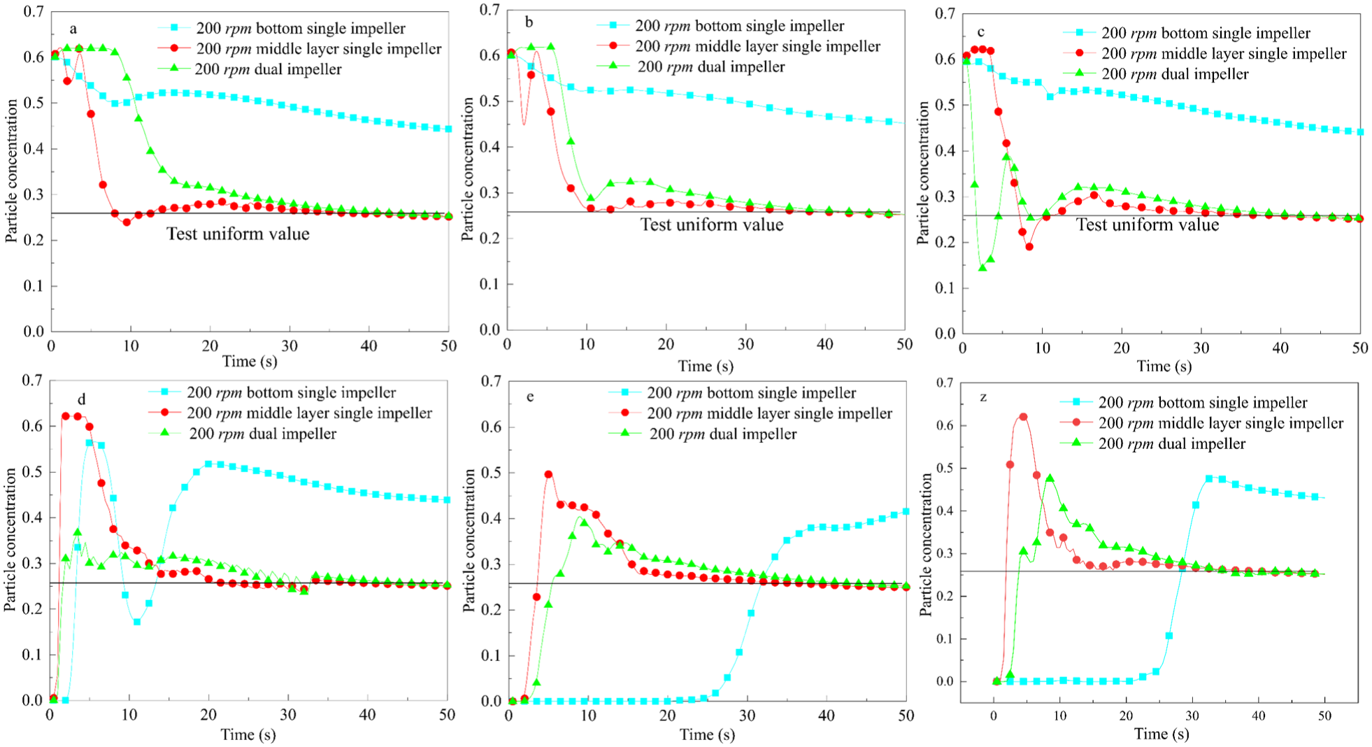
Furthermore, to gain a more nuanced understanding of the mixing process, a detailed analysis is conducted on the particle concentration distributions at specific monitoring points e and z, as depicted in Figure 19. This detailed examination of the mixing dynamics at different locations within the tank provides valuable insights into the spatial distribution of particle concentrations and the efficiency of the stirring process.

Influence of changes in impeller speed status at monitoring points e and z on concentration: (a) bottom impeller,(b) middle impeller, and (c) double impeller.
The concentration profiles at monitoring points e and z in Figure 19(a) provide further evidence of the significant advantages of operating at 200 rpm compared to 100 rpm. Specifically, Figure 19(b) and (c) illustrate that under 200 rpm, both the central single-impeller and dual-impeller configurations achieve particle concentrations that closely approximate or equal the experimental uniform mixing value of 0.26. In contrast, at 100 rpm, noticeable deviations from this value are observed. Focusing on the central region, the error in the stable concentration at point e under 200 rpm is merely 1.9%, while the corresponding error at point z under 100 rpm is also 1.9%. However, at 100 rpm, the errors at point e and z escalate to 34.6% and 46.2%, respectively. For the dual-impeller configuration, the error at point e under 200 rpm remains minimal at 1.9%, while at 100 rpm, the errors at points e and z increase to 7.69% and 11.5%, respectively.
In summary, the findings of this study indicate that positioning the impeller in the central location and operating at a rotational speed of 200 rpm represents an optimal solution for achieving rapid and uniform mixing within the agitator tank. This configuration not only enhances mixing efficiency but also minimizes deviations from the desired uniform concentration, thereby providing a robust and efficient mixing strategy for industrial applications.
Conclusion
This study delves into the pivotal influence of impeller configuration strategies on the homogeneity of gangue-slurry mixtures within agitator tanks, leveraging an integrated approach that combines comprehensive experimental validation with multiphase flow numerical simulation techniques. Three more elaborate and insightful conclusions are drawn as follows:
(1) Profound enhancement of homogeneity through optimized stirring speeds: The study unequivocally underscores stirring speed as a crucial factor modulating the mixing efficiency of gangue and slurry. Specifically, elevating the stirring speed from 100 to 200 rpm resulted in a remarkable average enhancement of 38.5% in the mixed concentration recorded at monitoring points e and z in the central region of the agitator. This outcome not only visually demonstrates the potent facilitating effect of increased speed on mixing uniformity but also underscores the practical significance of adjusting stirring speeds to significantly accelerate the fusion process between gangue and slurry, thereby ensuring the uniformity and stability of the mixed slurry’s quality.
(2) Marked optimization of mixing efficiency via central impeller placement: A comparative analysis of stirring effects under different impeller positions reveals that centrally positioned impellers outperform bottom-mounted configurations in achieving comprehensive and uniform mixing of materials within the agitator tank. Notably, the central impeller layout significantly reduces mixing time, requiring less time to achieve the same level of homogeneity compared to two-impeller configurations. This finding underscores its potential to enhance operational efficiency and energy savings in grouting projects. The optimized design of central impeller placement presents a novel approach and direction for achieving efficient and energy-saving mixing operations.
(3) Optimization of stirring strategies under synergistic multi-factor effects: Beyond exploring the impact of individual factors (such as stirring speed and impeller position), this study implicitly underscores the importance of multi-factor synergies in refining stirring strategies. Future endeavors that comprehensively consider various factors—including stirring speed, impeller quantity, positional distribution, and agitator tank structural characteristics—and conduct more meticulous designs and adjustments, promise to further elevate mixing efficiency and uniformity. Such advancements will pave the way for more scientific and efficient solutions in the preparation and application of gangue-slurry mixtures.
Footnotes
Handling Editor: Aarthy Esakkiappan
Funding
The authors disclosed receipt of the following financial support for the research, authorship, and/or publication of this article: This work is supported by Science and Technology Innovation Fund of Xi’an Research Institute of CCTEG(2024XAYJS03), Natural Science Basis Research Plan in Shaanxi Province of China (Program No. 2024JC-YBMS-230), Tiandi Science and Technology Co. Ltd. Science and Technology Innovation Venture Capital Special Project (2023-TD-ZD004-003), Science and Technology Innovation Fund of Xi’an Research Institute of CCTEG (2023X AYJS11).
Declaration of conflicting interests
The authors declared no potential conflicts of interest with respect to the research, authorship, and/or publication of this article.