
Abstract
A kind of launching platform driven by two permanent magnet synchronous motors which is used to launch kinetic load to hit the target always faces strong external disturbance such as the air current impulsion which would degrade their tracking accuracy greatly. In this article, the position control problem of a launching platform with strong disturbance is studied based on the finite time control technique. A sliding mode disturbance observer is proposed to observe the disturbance, based on which a finite time control technique is proposed for position loop. Rigorous mathematical analysis is given for the closed-loop system performance in the presence of disturbances. The experimental results show that this method not only makes the position tracking error of the closed-loop system converge faster but also makes the boundary of steady-state error smaller than that of the conventional proportional–integral–derivative control scheme and sliding mode control scheme, which means the closed-loop system has stronger anti-disturbance property.
Introduction
The launching platform is a typical mechatronic servo system, usually composed of a sensor (such as the photoelectric encoder), an actuator (such as an AC servo motor), a mechanical transmission mechanism (such as a turret, a rack, and a reducer.), load, and a controller. Figure 1 shows a typical launching platform, which is also a typical multi-variable strong-coupling nonlinear system. It is mainly used to launch kinetic load to hit the target, and it is applied in military and civilian fields widely, such as for anti-missile air defense to combat invading target and artificial rainfall to hit the target cumulonimbus. How to improve the tracking accuracy and robustness of launching platform is always a hot topic of scholars at home and abroad. The improvement of the comprehensive performance of the launching platform mainly faces the challenges as follows: (1) when the kinetic load is launched, a strong air current impulsion produced would exert strong external transient disturbance on the system and (2) when the azimuth rotary mechanism and the pitching rotary mechanism rotate around their respective rotation axis, a gyroscopic torque would be exerted on one mechanism by another mechanism as a disturbance due to the gyroscopic effect. All these factors would bring great difficulty to improve the accuracy of the system. To solve the problem of system model uncertainty including the parametric uncertain and the other uncertain nonlinearities such as the external disturbance and improve the tracking performance of electro-mechanical servo system just like the launching platform, many advanced nonlinear controllers have been investigated,1,2 such as adaptive robust control (ARC),3–6 adaptive backstepping control,7–9 active disturbance rejection control, 10 and neural network–based intelligent control. 11

The setup diagram of the small launching platform.
From the point of view of optimization, the control method of the finite time convergence is the optimal control method with respect to the time. In the control system, the convergence performance is a key performance index. The finite time convergence of the system means that the state of the system reaches equilibrium in a finite time and then always stays at the equilibrium point. Studies have shown that to control an uncertain system with interference, finite time control technology not only has a faster convergence in a neighborhood of the origin but also has a better robustness and anti-interference compared to an infinite time control technology (exponential convergence or general other asymptotically convergence). Therefore, finite time control technology’s advantages attract us to put it into the design of a nonlinear controller for the launching platform. Generally speaking, the design method of the finite time controller is classified into three types: the open-loop control method, the discontinuous state feedback control method, and the continuous state feedback control method. Open-loop control method lacks anti-interference ability and robustness, which leads to its limit in practical application. As the representative of the discontinuous feedback control method, bang–bang control is not easy to achieve and is easy to produce jitter and other issues. Therefore, the continuous feedback control method based on the system state is very worthy of study.
A finite time control problem for a permanent magnet synchronous motor (PMSM) speed servo system using different kinds of finite time control methods is presented in Wang et al. 12 Integral terminal sliding mode controller and continuous finite time controller are designed for the speed loop and compared with the corresponding control method of asymptotical stability; the controller based on the finite time control can make the output of system track the desired speed reference signal in finite time and obtain a better dynamic response and anti-disturbance performance. However, a large chattering phenomenon is caused by high switching gains. Thus, a composite integral terminal sliding mode control method based on disturbance observer is proposed to reduce chattering. Through feed-forward compensation based on disturbance estimation, the proposed controller can take a smaller switching gain, which could reduce chattering and simultaneously achieve a good disturbance rejection performance. In this article, by referring to the sliding mode technology in previous studies12–16 and integrating the forward compensation method in Krstic et al., 17 a novel finite time controller is proposed for a launching platform, in which a sliding mode disturbance observer is proposed to observe the external disturbance, and the final control law is derived based on the estimated disturbance produced by the observer. Compared with the control method in Wang et al., 12 the control value of the proposal is much smoother due to the special design and thus the chattering is reduced obviously.
This article is organized as follows. Dynamic model of a small launching platform is presented in section “Dynamics of a small launching platform.” Section “Design of finite time controller” gives the sliding mode disturbance observer and the finite time controller design procedure and theoretical results. Simulation and results are presented in section “Semi-physical simulation research.” Section “Conclusion” contains the conclusion.
Dynamics of a small launching platform
The launching platform is composed of an azimuth-axis servo subsystem and the pitch-axis servo subsystem, and each subsystem is composed of a controller, a servo driver, a servo motor, a speed reducer, a rotating mechanism, sensors, and so on. The specific system diagram is shown in Figure 1. In order to improve the control performance of the system, when building the system’s model, the effect of many nonlinear factors, such as the viscous friction and the coupling disturbance torque between the rotary mechanisms caused by gyroscopic effect, should be considered. In addition, only the mechanical dynamical characteristics are considered while the current’s dynamic characteristics are neglected when modeling since the electrical response speed is much higher than the mechanical response speed.
Since the mathematic model of azimuth-axis servo subsystem is almost the same as that of the pitch-axis servo system, here the azimuth-axis servo subsystem is taken as the research object first. The coupling disturbance torque applied on one servo subsystem by another servo subsystem caused by gyroscopic effect is regarded as a time-varying disturbance in the servo subsystem. Thus, the controller design for the pitch-axis servo subsystem is the same as that for the azimuth-axis servo subsystem, so we just show how to design the controller for the azimuth-axis servo subsystem and show the control performance of azimuth-axis servo subsystem. Considering all the above factors, the mathematical model of the azimuth-axis servo system can be expressed as

where Jequ is the equivalent inertia of the PMSM’s rotor and load; y is the output position of azimuth axis of the launching platform; ku is the voltage-torque coefficient; Bequ is the equivalent viscous friction coefficient;

To design the controller, we need to build the system’s state equation. Denote

where
Design of finite time controller
Sliding mode disturbance observer design
In this section, the design process of the sliding mode observer will be given. To design a sliding mode disturbance observer with finite time convergence property, the following sliding mode surface of the observer is introduced

where z1 is the internal dynamics of the observer and it is designed as

where k1, β1, ε1, p1, and q1 are the coefficients of the disturbance observer, p1 < q1 and they are all the positive odd numbers, k1, β1, and ε1 are all the positive numbers and β1 ≥ D ≥ |d(x,t)|
Differentiating equation (4) and substituting the second item of equations (3) and (5) into it, we could obtain

Then, design the estimation of

Lemma 1(Man and Yu 18 )
Assume that there exists a continuous positive definite function V0(t) which satisfies the following inequality

then V0(t) converges to the equilibrium point in finite time ts

where α > 0, λ > 0, and 0 < γ < 1.
Theorem 1
Considering the nonlinear system with model uncertainty (equation (3)), the sliding mode disturbance observer is designed according to equations (4), (5), and (8). Then, the disturbance approximation error of the proposed sliding mode disturbance observer is convergent in the finite time, when the output is measured at discrete sampling times with a sufficiently small sampling interval without measurement errors.
Proof
See Appendix 1.
Remark 1
The proposed sliding mode disturbance observer still requires that the external disturbance d(x,t) has a known upper boundary, that is, β1 ≥ D, just like most of the existing sliding mode disturbance observers. Comparing with the existing results, the proposed sliding mode disturbance observer can guarantee the disturbance estimate error convergent to zero in the finite time. However, the premise is that there’s no noise and sampling interval is small enough. In addition, the disturbance approximation error converges only in the sense of equivalent values, since the proposed disturbance estimation law (equation (8)) contains switching terms.
Finite time controller design
In this section, we develop the tracking control scheme for the case where all states are available using sliding mode control approach. To develop the sliding mode tracking control, we define


where xd(t) is the desired position signal and xd(t) is continuous of order 2, and
A sliding mode surface of controller is given by

where λ0, λ1, α1, and α2 are the parameters of the controller and all of them are bigger than zero. λ0 and λ1 could make the expression s2 + λ1 s + λ0 Hurwitz, where s is the differential operator. α1 and α2 satisfy α1 = α2/(2−α2), α2∈ (0,1).
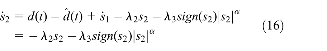
The time derivative of s2 is given by

Design the control law u as

where λ2, λ3, and α are the parameters of the controller and λ2 > 0, λ3 > 0, and 0 < α < 1.
Substituting equation (15) into equation (14), we could have
Main results
Lemma 2 (Man and Yu 18 )
Let k1, …, kn > 0 be such that the polynomial sn + kn sn−1 + k2s + k1 is Hurwitz and consider the system

There exists β ∈ (0, 1) such that, for every α ∈ (1 − β, 1), the origin is a globally finite time-stable equilibrium for the system (equation (17)) under the feedback

where α1, …, αn satisfy
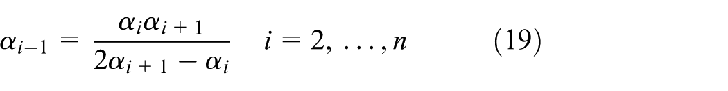
with αn + 1 = 1 and αn = α.
According to the controller designed above, we could get the theorem as given below.
Theorem 2
Considering the nonlinear system with the external disturbance (equation (3)) and assuming full state information available, the tracking error of the closed-loop system is convergent in the finite time with the proposed sliding mode disturbance observer from equations (4), (5), and (8) and sliding mode tracking control law from equations (13) and (15).
Proof
See Appendix 1.
Remark 2
Although the external disturbance is required to have an upper boundary to make the estimation error of the disturbance observer convergent to zero in the finite time, the boundary of the external disturbance is not directly used to design the tracking control law. Thus, the control law is more applicable in reality. In addition, the proposed disturbance observer–based sliding mode tracking control can explore the information about the characteristic of disturbances, since the output of the sliding mode disturbance observer is used in the design of the sliding mode tracking control law (equation (15)). It is worth to point out that s2 in equation (13) has an additional term s1. The reason is that the disturbance observer’s sliding mode surface s1 should be considered in the controller’s sliding mode surface s2 to analyze the stability of the whole closed-loop system.
Semi-physical simulation research
To verify the feasibility of the proposed sliding mode observer–based finite time controller (SMFTC), a semi-physical simulation platform has been built, which is composed of a servo motor, a reducer, a load, a sensor, and so on and each part just simulates the corresponding part of a real launching platform. Extensive experiments have been carried out on it. The parameters of the semi-physical simulation platform are given as follows (Figure 2):
Equivalent inertia: Jequ = 0.00138 kg m2;
Equivalent viscous friction coefficient: Beq = 0.4 N m s/rad;
Voltage-torque coefficient: ku = 1.36 N m/V.

Semi-physical simulation platform.
The following three controllers are compared:
Proportional–integral–derivative (PID). This is the traditional position-velocity-current three-loop PID controller. For this controller implementation, the motor driver is set at the velocity loop. The position-loop PID controller is implemented in the real-time control software, and its gains tuned carefully via an error-and-try method kp = 3, ki = 0.15, and kd = 0, which denote the proportional gain, integral gain, and derivative gain, respectively.
Sliding mode controller (SMC). This is a classic sliding mode controller proposed in Rubagotti et al.
19
The guideline for choosing the controller’s parameters c1, c2, and k is that c1 and c2 should be chosen to make
Sliding mode observer based finite time controller (SMFTC). The finite time controller (equation (15)) with sliding mode disturbance observer (equation (8)) is proposed in this article and described in section “Design of finite time controller.” According to Lemma 1,
The three controllers are first tested for a sinusoidal-like motion trajectory (x1d = 300 × sin(3.14 t))(1−exp(−0.01t)) (°) and two cases are tested for normal motion trajectory:
Position disturbance case. The position disturbance is implemented by applying u − 0.22x1 to the physical motion system. This type of disturbance will change d(x,t) greatly, and the system will be operated under heavy unstructured uncertainties.
Position-velocity-input disturbance case. This disturbance is implemented by applying 0.5u − 0.15x2 − 0.28x1 to the physical motion system. Similarly, this type of disturbance will greatly change the parameters θ1 and θ2, together with d(x,t). The dynamics of the system are almost completely changed and can be thought as the most exhaustive verification.
In addition, a simulated coupling disturbance is applied to the physical system in both cases and the coupling coefficients c1 = 0.16 N m s/rad and c2 = 0.18 N m s/rad. What’s more, when t = 3 s, a step-disturbance of 1.3*(1 − exp(−20(t−3)3)) N m is applied to the physical system in both cases.
Case 1. The desired motion trajectory and corresponding tracking performance under the three controllers are shown in Figure 3. As seen, the SMC controllers have better performance than PID controller in terms of both transient and final tracking errors since it employed varying structure control method to undermine the influence of the external disturbance. However, the SMFTC has the best tracking performance in all three controllers with a maximal steady tracking error about 0.01°. The reason is that the sliding mode–based observer could capture the disturbance, which could be compensated in the finite time controller (the disturbance estimation is shown in Figure 4, from which we could see that the settling time of disturbance observation is about 4 s, and the control input value is shown in Figure 5). Thus, the total uncertainties are greatly reduced and the tracking performance has been greatly improved. In addition, the finite time control technique helps it converge to its equilibrium state faster and more accurately.

Tracking errors of the three controllers in position disturbance case.

The disturbance observed by the sliding mode observer and its error.

The control value of SMFTC and SMC in position disturbance case.
Case 2. To further test the robustness of the proposed algorithm to the external disturbance, the position disturbance is added, which will be the dominant factor affecting the tracking performance. The tracking performance of the three controllers is shown in Figure 6. The disturbance estimation of SMFTC is shown in Figure 7 from which we could see that the settling time of disturbance observation is still about 4 s and the control input value is shown in Figure 8. As seen, even with strong unstructured disturbances, the proposed SMFTC and SMC are able to attenuate unexpected effects. Contrarily, the PID controller exhibits bad performance. However, the SMFTC has a faster convergence rate and a smaller steady tracking error about 0.01° than SMC has. The reason is that the power item in the finite time controller could make the control value bigger and thus inhibit the influence of the disturbance faster when the error is small.

Tracking errors of the three controllers in position-velocity-input disturbance case.

The disturbance observed by the sliding mode observer and its error.

The control value of SMFTC and SMC in position-velocity-input disturbance case.
Conclusion
In this article, a finite time controller with sliding mode disturbance observer has been proposed for the motion control of a launching platform driven by two PMSM motors. The stability of the closed-loop system is ensured via Lyapunov’s method, which shows that the proposed controller could guarantee that the tracking error of the closed-loop system is convergent in the finite time. Compared with the general control method of asymptotical stability, the controller based on the finite time control can make the output of system track the desired reference signal in a finite time and obtain a better dynamic response and anti-disturbance performance. Through feed-forward compensation based on disturbance estimation and special design, the proposed controller produces a smoother control value, which could reduce chattering and simultaneously achieve a good disturbance rejection performance. Comparative experimental results are obtained to illustrate the effectiveness of the proposed scheme.
Footnotes
Appendix 1
Academic Editor: Nasim Ullah
Declaration of conflicting interests
The author(s) declared no potential conflicts of interest with respect to the research, authorship, and/or publication of this article.
Funding
The author(s) disclosed receipt of the following financial support for the research, authorship, and/or publication of this article: This work was supported by the National Natural Science Foundation of China under Grant 51505224, the Natural Science Foundation of Jiangsu Province in China under Grant BK20150776, and the National Natural Science Foundation of China under Grant 51305203.