
Abstract
This article investigates the volume change law of trapped fluid in the meshing process and the flow characteristics of external gear pumps under the following two cases: the pump design with and without relief groove. In this study, a mathematical modeling of gear pairs is deduced based on the meshing theory and a complete set of mathematical equations of tooth profile, and the flow rate equation is derived based on law of conservation of mass across the changing boundaries of a control volume. During the process, the function of the pump displacement is established, which is formed by two parts: tooth space volume and trapped volume. In addition, using a control volume approach, the trapped volume and flow rate characteristics of the pump under different design parameters of gears are discussed. The results show that the curve of trapped volume is similar to a parabola and the pump designed with a large number of teeth, module, and pressure angle easily obtained good flow rate characteristics under the same condition, which have a great benefit for designing the relief grooves and external gear pumps.
Keywords
Introduction
The well-known advantages of external gear pumps such as low manufacturing cost, compactness, high reliability, and excellent performance make them as one of the prominently used components in fluid power. External gear pumps are also ideal equipment for conveying high-viscosity liquids. 1 Depending on meshing form, there are two main different types of gear pumps: external and internal. Within relative to internal gear pumps, external gear pumps convert mechanical powers into hydraulic fluid powers with high pressures. This is particularly true in measurement and lubrication systems.
The gear pump is simple in its operating principle, as the gears rotate the fluid is transferred from inlet port to outlet port around the outside of gears, and the displacement of the fluid is accomplished by two meshing gears rotating against each other. 2 Gear teeth routinely carry the fluid at a periodic interval that causes the flow rate and pressure in the intake and discharge to vary periodically and these variations are referred to as flow and pressure ripples. When two gears meshing with each other, it will form a closed cavity which separates suction side and discharge side, known as the trapped volume. The trapped volume of fluid with rapid changes results in the generation of pressures above and below the inlet and discharge pressures. Excessive over-pressure can lead to high loading of the gears and excessive mechanical losses, cause vibrations and noises, affecting the stationarity and stress of the gear machine. Under-pressure can result in cavitation. Therefore, meshing actions make a significant contribution to pressure and flow ripples that are critical dynamics affecting system’s lifetime performance. Generally, gears can dig their relief grooves on the side plates or wear plates to reduce the localized pressure spikes and fluid cavitation in the meshing volumes.
Two main sources of noise and vibration are pressure pulsation and gear meshing. Meanwhile, the periodic variation of gear meshing forces can produce pressure ripples. So, the investigation of the flow rate performances of pumps has been a subject of considerable interest for many years. Manring and Kasaragadda 3 used the control volume method to calculate the instantaneous flow rate of external gear pumps with different teeth numbers of the driving and the driven gears. They pointed out that a higher teeth number for the driving gear or the driven gear can decrease flow pulsation. However, they did not consider the influence of trapped volume on the flow characteristics of the pumps. Foster et al. 4 investigated the flow performance of external gear pumps under cyclic excitations adopting swept volume method. This work considered the trapped volume of fluid between meshing teeth, where the changes of trapped volume can be calculated using a geometric formula. Huang and Lian 5 considered a closed flow rate formula to represent flow characteristics of external spur gear pumps and accurately calculated pump flow rates and fluctuation coefficients and further discussed the effect of design parameters of gear on the flow pulsation. Tooth profile and the hole size of wear plates exert an influence on the trapped volume of fluid and instantaneous flow rate of gear pumps. For this reason, some researches addressed their studies on the structure of gear pumps which include new designs or modifications of wear plates or tooth profile and so on. Wang et al. 6 utilized the optimization theorem to design gear wear plates to cut down the instantaneous pressure spikes of the meshing action in the external gear pumps and motors, where computational method of the gear pocket volumes adopted swept volume method. The result was that this method reduced the pressure variations and spikes and achieved the better system performance. In 2011, Wang et al. 7 proposed a numerical model for the entire gear pumps using the generalized control volumes method, especially for gear teeth within the meshing zone and calculated the orifice areas of side plates and flow rate of the gear pumps. Devendran and Vacca 8 presented a novel design concept that the inlet/outlet grooves were machined in the sliding bushings to realize a variable timing for the connections of each tooth space volume with the inlet and outlet ports and established the mathematical modeling of tooth profile. This article took into account the meshing points and the results were shown to compare nicely with actual test data. Lin et al. 9 presented a new general numerical method used to calculate the tooth profile of a non-circular curved face gear. Ellen Bergseth and Stefan Björklund 10 adopted a logarithmical profile modification method to reduce the contact pressure at a specific normal load. Alipiev 11 used realized potential method to investigate the geometric design of symmetric and asymmetric teeth of involute gears in the meshing process. Liang et al. 12 studied transmission efficiency of gear drive and the geometric design with double circular arc-involute tooth profile. Other researches employed lumped parameter approach to predict the instantaneous flow and pressure particularly in the meshing area of gear pumps.13,14 In order to investigate the geometric design of the gear tooth profile and the body of the pump influence on flow characteristics of gear pump, Nagamura et al. 15 derived three types of non-involute tooth profiles and calculated accurately the displacement volume to optimize the pump performance. The numerical modeling method generated results in good agreement with the experimental results. Saleem 16 has analyzed tooth geometry effect on the performance of the gear pumps, and the results show that the pump with unstandard gears have a high flow rate and small trapped volume. Although there are many studies in these fields, to the authors’ best knowledge, there has been little research on calculating the flow rate of pumps which has taken the trapped volume into account being a part of pump displacement.
In this article, the mathematical equations of tooth profiles and the mathematical modeling of gear pairs for the change of trapped fluid volume in the meshing cycle and flow characteristics are established on the basis of the gear tooth shape configuration of external gear pumps. The calculation method for displacement of pumps based on trapped volume is presented and the control volume method is employed for the flow rate calculation. Using the model and method, the volume of trapped fluid and the flow characteristics depending on the pump-operating conditions could be quantitatively analyzed.
The content of the article is organized as follows: Section “Mathematical model of the gear pairs” introduces and explains the tooth configuration and establishes the mathematical models of tooth profiles and gear pairs. Section “Calculation method for pump flow characteristics” proposes the calculation approach with control volume, including instantaneous flow rate, flow rate fluctuation coefficient, and displacement of the pump. Section “Results analysis and discussion” analyzes the flow rates with and without relief grooves, resumes the precise value validation results, and discusses the gear parameters’ influence on the trapped volume and flow characteristics. Section “Conclusion” concludes the research.
Mathematical model of the gear pairs
Geometry of tooth profiles and mathematical models
Trapped volume study is fundamental in the research of meshing flows. In order to calculate precisely and accurately the trapped volume, the coordinate system of a symmetric involute tooth shape is shown in Figure 1. The tooth profile of the involute gear is composed of tip circle, involute, root fillet trochoid, and root circle. These portions are mathematically expressed as follows:
Involute equation
where

Tip circle

where
Root fillet trochoid
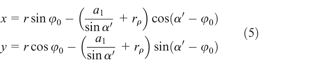
This article adopted the hobbing cutter as a rack cutter. For a rack cutter with two round edges, the machining parameters of the tool are defined as 18

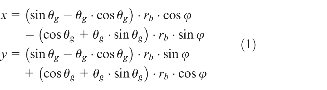
the root fillet trochoid is the equidistant line of the prolate involute. In the process of pinion machining, the pitch line of tool is tangent to the pitch circle of gears and makes pure rolling. Therefore, the equation for the root fillet trochoid on the end face can be written as
where

Root circle

When the parameter

Coordinate system for the involute tooth shape.
Mathematical models of the gear pairs
The mathematical model for the complete tooth shape of involute gears can be obtained by the equations characterizing the tooth profiles. It is assumed that
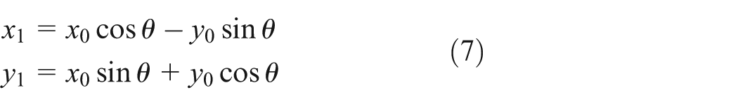
where
Two different reference coordinates for each gear are shown in Figure 2, both having their origins coinciding with the centers of the gears. Where 1 is the driving gear and 2 is the driven gear. The coordinate systems

Meshing coordinate systems of gear pairs.
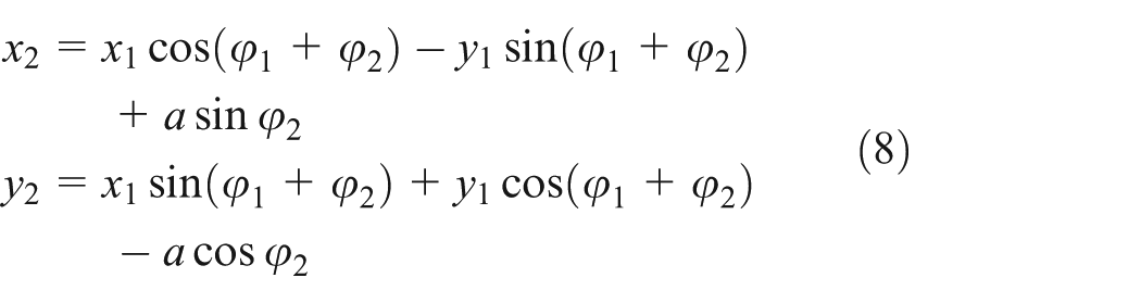
According to the kinematics of gear geometry and theory of gearing,
17
the conjugate tooth profile of gear 2 can be deemed as the envelope of the tooth profile of gear 1 in coordinate system. Using the coordinate transformation from
Calculation method for pump flow characteristics
In the following analysis, it is assumed that the gear pump is an ideal pump, the pump parts are rigid and inflexible, and there is no leakage flow between the gear faces and the side plates. Control volume approach and energy method14,19 are the two main methods for instantaneous flow rate calculation in gear pump. This article adopts control volume approach to analyze the flow characteristics of gear pump.
Instantaneous flow rate of the pump
Figure 3 shows a crosshatched area that defines the control region at discharge chamber of the gear pump.


Control volume of the discharge side in the gear pump.
The gear axial thickness has no effect on the kinematic flow ripple of the pump, so a unit thickness is considered. In the geometry of two meshing gears, the entering and exiting volumes are given by

where

Substituting equations (10) and (11) into equation (9) yields the following result for the instantaneous flow rate of the pump

Using this equation, the instantaneous flow rate of the pump may be determined once the instantaneous meshing point radii
Displacement and flow rate fluctuation coefficient
The external gear pump is configured with an identical number of teeth on each pair of meshing gears, so the tooth space volume
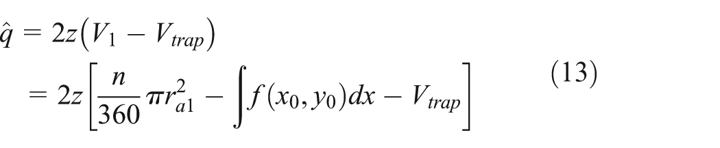
where n is the central angle of tooth profile, and

where

Meshing process of one tooth pair: (a) first phase: from starting the driving gear root promote driven gear tip (maximum trapped volume
The average flow rate for one flow pulsation is defined as

The flow rate fluctuation coefficient is defined as

Results analysis and discussion
Using the mathematical method described in the previous sections, the volume changes of trapped area with the rotation angle of gear and the flow characteristics of gear pumps can be obtained. A MATLAB code was developed to numerically simulate the changes of trapped volume and flow characteristics. In the case studies, the driving gear and the driven gear have the same parameters. The gears data are given as follows: number of teeth = 10, module = 3, pressure angle = 20°, addendum coefficient = 1, radial clearance coefficient = 0.25, addendum modification coefficient = 0, and the rotational speed of engine takes 1200 r/min.
The variation of trapped volume
One meshing cycle of one tooth from the beginning of engagement to the end of engagement was set as the investigation target. The volume changes of trapped area are shown in Figure 5, where

The variation curves of trapped volume.
From Figure 5, the curve shape of trapped area is similar to a parabola and the variation curves of trapped volume
Flow rate and relief grooves
In Figure 6, the mathematical model of the modification value for the displacement of pump has been used by this form from Cunxing. 19 The calculation results of two methods are negligible, which indicate that this new method is correct.

The comparison of the modification value and the value of calculation method.
In Figure 7, the amplitude of the flow pulse of pumps with relief groove is smaller than without relief groove during three meshing cycles. The flow rate without relief groove has the maximum of

Flow rates with and without relief grooves.
Volume of trapped fluid and flow rate characteristics under different design parameters
In this section, the influence of gear design parameters on trapped volumes of gear pumps is investigated. The design parameters of gear pairs include the number of teeth, module, and pressure angle. Gear sizes are kept to be the same as those given in above section with the exception of the specified parameter under discussion.
Number of teeth
The change of trapped volumes and flow rate characteristics with different numbers of teeth are illustrated in Figure 8.
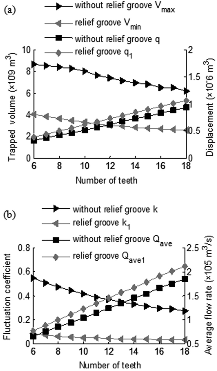
Influences of teeth number for pumps with and without relief grooves: (a) trapped volume and displacement and (b) average flow rate and flow rate fluctuation coefficient.
In Figure 8(a), two gray lines represent the curves of minimum trapped volume
In Figure 8(b), two gray lines represent the curves of flow rate fluctuation coefficient
Module
The trapped volumes and flow rate characteristics change with various modules are illustrated in Figure 9.
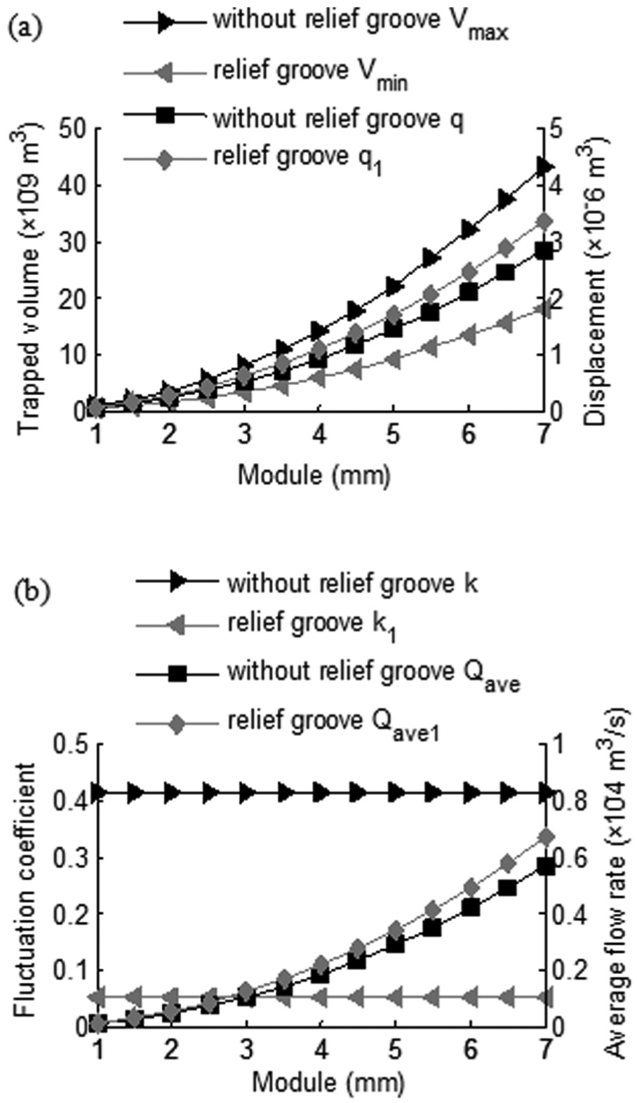
Influences of modules for pumps with and without relief grooves: (a) trapped volume and displacement and (b) average flow rate and flow rate fluctuation coefficient.
In Figure 9(a), the line color description is the same as Figure 8(a). The maximum trapped volume increases, while the modules are increased from 1 to 7 mm and the displacement of pump increases too, with or without relief groove. In the same way, the minimum trapped volume increases with the increased modules. Besides, the growth trend of four curves is consistent. Within the range of modules varied (1–7 mm), no marked variations in growth trend, trapped volume, or displacement were shown.
In Figure 9(b), the line color description is the same as in Figure 8(b). Figure 9(b) illustrates that the various modules does not change the flow rate fluctuation coefficient of pump, but the average flow rate increases by increasing the modules in terms of the pump design with or without relief groove. The flow rate fluctuation coefficient is a certain value 0.4126 for the pump design without relief groove, in contrast, the flow rate fluctuation coefficient of pump design with relief groove is 0.0503 under the same conditions, which means, in the latter case, the flow rate fluctuation coefficient reduced by 87.8%. Furthermore, the average flow rate has no significant change in both cases. In summary, it is one that can be used to one’s advantage for making a larger module of external gear pumps as designed, other conditions being equal.
Pressure angle
The trapped volumes and flow rate characteristics change with different gear pressure angles between 14° and 22° are discussed. In Figure 10(a), the line color description is the same as in Figure 8(a). The maximum trapped volume decreases with the increased pressure angle, but the displacement of pump has just the opposite change trend when the pumps without relief groove. For the pump design with relief groove, the minimum trapped volume gets bigger with pressure angle increasing, and the displacement of pump is not sensitive to the pressure angle.

Influences of pressure angle for pumps with and without relief grooves: (a) trapped volume and displacement and (b) average flow rate and flow rate fluctuation coefficient.
In Figure 10(b), the line color description is the same as in Figure 8(b). Figure 10(b) shows that increasing pressure angle will lead to a gradual average flow rate change (trend) and flow rate fluctuation coefficient decrease for the pump design without relief groove. It is assumed that the pump design with relief groove. From Figure 10(b), it may also be observed that a slight increase in the average flow rate may be achieved if pressure angle of external gear pump goes up. Moreover, as we have shown already, the flow rate fluctuation coefficient is fairly insensitive to pressure angle change. These trends suggest that a larger pressure angle of pump (with the same design parameters) may be designed under the condition of gear pump with relief groove.
Conclusion
This article presented a numerical solution method using the control volume approach to investigate how the trapped volumes change with the rotation angle and the flow characteristics of external gear pumps in both cases where the pump design with and without relief groove. This method includes the mathematical models of tooth profiles and gear pairs while the numerical simulations were performed with MATLAB packages.
In order to establish an accurate mathematical model, a complete set of mathematical equations describing tooth profiles, including tip circle, involute, root fillet trochoid, and root circle, are employed. Based on the meshing theory and tooth profile equations, the mathematical model of gear pairs is deduced. Meanwhile, the function for displacement of pump has been developed. Numerical solution method is based on control volume approach to compute instantaneous volume changes of trapped fluid and flow characteristics of pumps. In addition, the influence of gear parameters on the trapped volume and flow characteristics were investigated. The following conclusions can be drawn from this research:
The curve shape of trapped volume is similar to a parabola, and the flow rate fluctuation coefficient reduces 86.6% of the pump designed with relief groove than without relief groove.
In both cases, of the pump with and without relief groove, the maximum and minimum trapped volumes decrease with increasing numbers of teeth, and the displacement or average flow rate increases with increasing numbers of teeth. Moreover, the flow rate fluctuation coefficient decreases with increasing it.
Increasing the modules may be used to increase the trapped volumes, displacement, and average flow rate. This can be done without altering the flow rate fluctuation coefficient.
A larger pressure angle is helpful to reduce the volume of trapped fluid and increase the displacement and average flow rate; meanwhile, the flow rate fluctuation coefficient reduces as well for the pump design without relief groove. Compared with the former, changing the pressure angle has a negligible impact on the displacement, average flow rate, and the flow rate fluctuation coefficient of the pump design with relief groove.
In summary, the results of this study show that it may be advantageous to design the relief groove or external gear pumps with a large number of teeth, module, and pressure angle under the same condition.
Footnotes
Appendix 1
Academic Editor: Jose Ramon Serrano
Declaration of conflicting interests
The author(s) declared no potential conflicts of interest with respect to the research, authorship, and/or publication of this article.
Funding
The author(s) disclosed receipt of the following financial support for the research, authorship, and/or publication of this article: This research was supported by the National Natural Science Foundation of China (Grant No. 51574161).