
Abstract
The shaft manufacturing bending deviation occurs frequently in many types of shaft applications, such as crank shaft and roller shaft, and this issue will eventually affect the overall dynamic performance of the rotor–shaft-bearing system. In this study, a systematic modeling approach is developed to analyze the effect of shaft manufacturing bending deviation on the dynamic behavior of the geared rotor system. To validate the proposed approach, a practical example of spur geared rotor system was used and the shaft manufacturing bending deviation data were measured by a shaft testing bench. The whole system was modeled using a finite element method and the dynamic characteristics of meshing gear pair were represented by a coupled torsional–lateral gear dynamic model. Then, the effects of the dynamic gear mesh force, magnitude of deviation, position of deviation, and rotating speed on the dynamic responses of the geared rotor system were evaluated. The calculation results show that these parameters have different effects on the systematic vibration response of the geared rotor system, indicating that the geared rotor system has different dynamic sensitivities to those different excitations. This study helps to get a better understanding of the dynamic behavior of the geared rotor system with shaft bending deviation and can provide guidance for quality control of shaft manufacturing process in view of system dynamics.
Introduction
Rotating machines are extensively used throughout the engineering applications for power generation and transmission. In these applications, the geared rotor systems are typically employed for changing speeds and/or working direction. On account of the increasing demand for high speed and light weight, the research in the field of geared rotor dynamics becomes more and more important. This is because the geared rotor system under high-speed operating conditions tends to have more severe noise and vibration, durability, and efficiency issues, especially when there are manufacturing deviations of components such as shaft. Therefore, it is essential to investigate the dynamic behavior of the geared rotor system with certain shaft deviations to gain an in-depth understanding of the underlying physics to facilitate the design and development of quieter and more durable geared rotor systems.
The dynamic behavior of the rotors has been studied for over one century and analysis techniques of rotor dynamics have been fairly well established. 1 Approaches to dynamic analysis of the rotor systems can be divided into three main branches, that is, analytical models, transfer metric method (TMM), and finite element method (FEM). Analytical methods for rotor dynamic analysis were formulated in early models. 2 TMM was first proposed by Prohl 3 and solves rotor dynamic problems in the frequency domain. Later, many researchers4–6 continuously developed the TMM and published plenty of articles in the open literature. Nelson and McVaugh, 7 one of the pioneers, developed a model using the FEM to analyze the dynamic behavior of rotor-bearing system. Later, they improved the proposed model by including secondary effects such as rotary inertial, internal damping, and axial torque.8,9
The dynamic behavior of the geared rotor system is different from typical rotor-bearing system, where lateral and torsional vibrations can be conducted separately. Mitchell and Mellen 10 experimentally studied the dynamic property of the geared rotor system, and their results showed that the coupling effect between lateral and torsional vibrations should not be neglected. This is mainly because of the presence of the gear mesh characteristics in the geared rotor system. Therefore, for high-speed gear system, the gear mesh dynamic behavior needs to be taken into account when analyzing the dynamic characteristics of the geared rotor system. Early research works on the dynamics of the geared rotor system mostly modeled gear as rigid disk neglecting the dynamic gear mesh property. 7 Recently, Choi and Mau 11 conducted an analytical study of the dynamic characteristics of a geared rotor-bearing system by the TMM. In their study, they modeled the gear mesh as a pair of rigid disks connected by a spring–damper set. The steady-state response due to the excitation of mass unbalance, geometric eccentricity, and transmission error (TE) was obtained using TMM. Lee et al. 12 analyzed the coupled vibration characteristics of a turbo-chiller rotor-bearing system having a bull-pinion speed increasing gear, using a coupled lateral and torsional vibration FEM of a gear pair. Later, they obtained the unbalance response orbit of a gear-coupled two-shaft rotor-bearing system using FEM. 13 Most recently, Q Han et al. 14 studied the dynamic behavior of a geared rotor-bearing system with a breathing slant crack using FEM.
These previous research works focus on different aspects of the dynamic characteristics of geared rotor system and lead to improvements in understanding the dynamics of the geared rotor system. The importance of the coupled lateral—torsional vibration modes in geared rotor systems has received increasing attention in the past decade.15,16 It has been shown in some studies that the gear–shaft interaction has considerable influence on the gear mesh and bearing responses due to the coupling between gear mesh modes and shaft bending flexibility.17,18 The effect of shaft geometric variations has been studied by Richards and Pines, 19 in the aim of reducing gear mesh vibration. The effect of various errors, including shaft misalignments,20,21 eccentricity,22,23 and unbalance, 24 has also been studied by many researchers. Most recently, the effects of shaft bow and unbalance are investigated theoretically and experimentally.25,26 However, relatively less work has been reported on the effect of shaft manufacturing bending deviation on the dynamic property of geared rotor system. Shaft manufacturing bending deviation is inherently unavoidable and can be found in many types of practical application of shafts, such as crank shaft and roller shaft.27,28 As modern geared systems developed to transfer higher load and speed with lighter weight and smaller capacity, the geared system is much more sensitive to excitations from manufacturing deviations, for example, shaft bending deviation. Therefore, evaluation of shaft manufacturing bending deviation on the dynamic behavior of the geared rotor system is needed to be conducted.
The objective of this article is to theoretically evaluate the effect of shaft bending deviation on the dynamic characteristics of the geared rotor system. The whole theoretical model is established using coupled FEM approach for supporting shafts and lumped parameter model for the gear mesh dynamics. This article is organized as follows: the first segment aims at collecting the shaft manufacturing bending deviation data. Then the modeling approach of the geared rotor system is discussed in section “Geared rotor system” and the coupled torsional–lateral gear dynamic model is introduced in section “Gear mesh dynamics model.” Case studies of dynamic analysis of shaft manufacturing bending deviation are conducted in section “Case study” which is followed by conclusion in section “Summary.”
Shaft with bending deviation
Shaft bending deviation is one of the frequently found shaft manufacturing deviations, and it comes from machining process and heat-treatment process. It is inherently unavoidable for a slender shaft such as crank shaft used in automotive engine and roller shaft applied in the textile machine. The characteristic of the shaft bending deviation is three-dimensional and totally random distributed, as shown in Figure 1. However, there are general regularities which show that the bending deviation is consisted of the first few bending orders in each plane including XY and XZ 27 as shown in Figure 2. This makes it possible to model the shaft bending deviations in each plane and correspondingly obtain the unbalance force caused by the deviations.
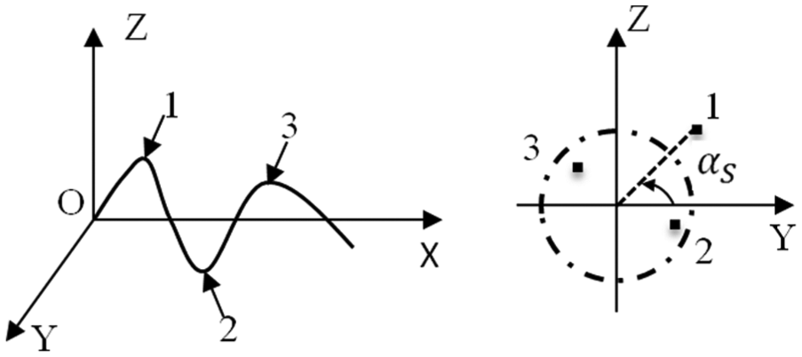
Shaft manufacturing bending deviation.

Shaft micro-bending shapes.
In this study, the shaft bending deviations were measured using a shaft testing/straightening bench as shown in Figure 3. This shaft testing/straightening bench was developed by our research group and can measure the three-directional information of shaft micro-geometry.
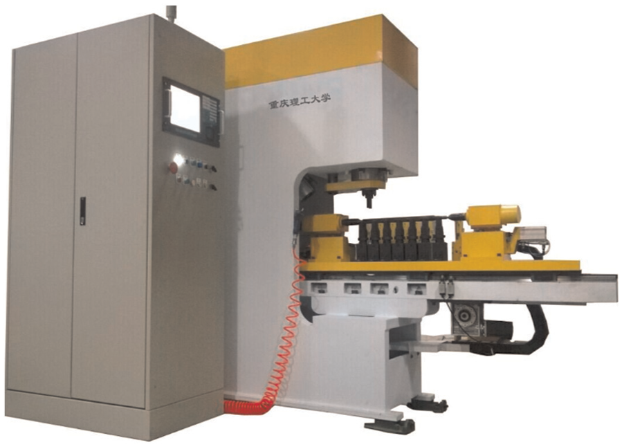
Shaft testing bench.
Geared rotor system
Rotor coordinate
Typical geared rotor system mainly consists of gear, shaft, and supporting bearings. The coordinate of the rotors, described in

where


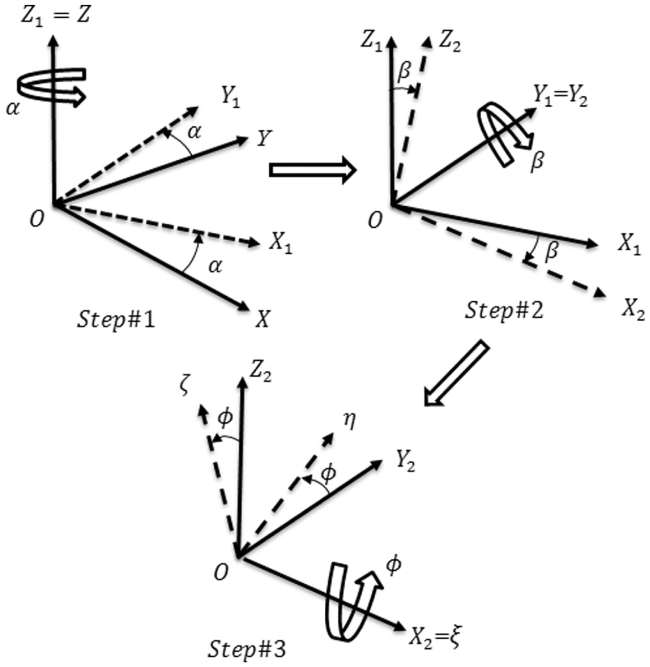
Rotor coordinate transformation.
The rotor angular velocity

Shaft modeling
The shaft is modeled using FEM in this study. The finite shaft element has two nodes, namely,

where


Finite shaft element.
The translational mass of the finite shaft element can be described as

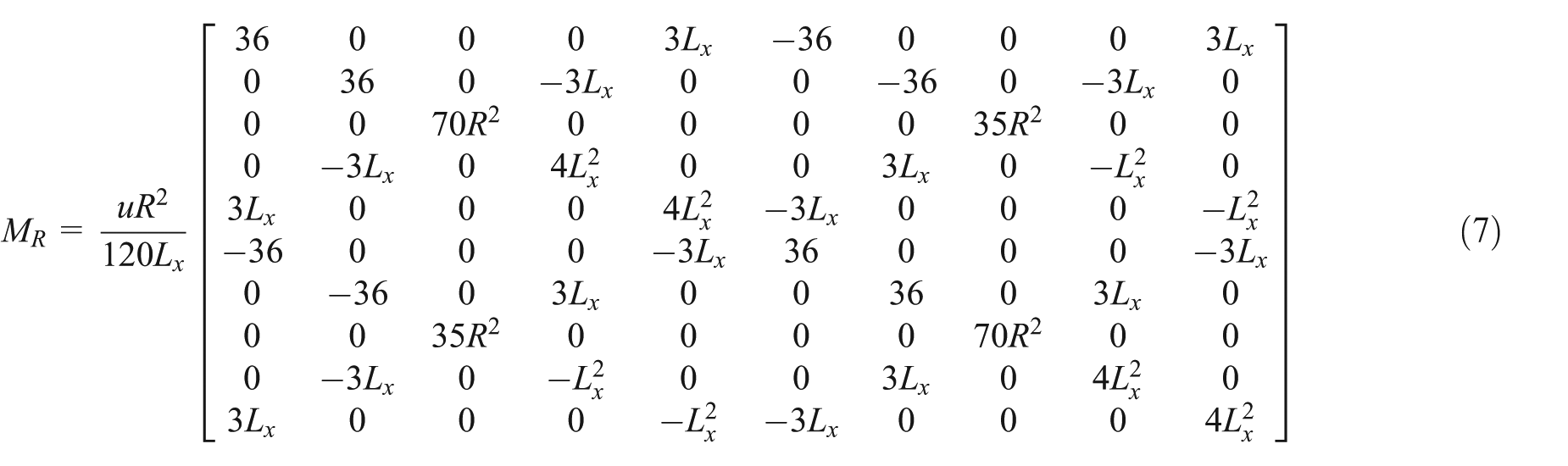
The rotational mass of the finite shaft element can be described as
The gyroscopic matrix of the finite shaft element

The stiffness matrix of the finite shaft element

where Lx is the length of the shaft element;
System assembly
The example geared system in this study has two meshing spur gears as schematically shown in Figure 6. Both pinion and gear are fixed in the middle of the shafts supported by two bearings. Both shafts were modeled using FEM and each shaft totally has 12 elements and 13 nodes. The bearings were described by mechanical spring–damper model and linearly coupled with the end nodes of both shafts. 1 The gear and pinion were represented by the rigid disk and linearly coupled with node 6 of both shafts. The dynamic gear mesh characteristics were obtained using a coupled torsional–lateral gear dynamic model and the dynamic mesh force was used as the coupling effect between each geared rotor system. Detailed information of the dynamic mesh force is shown in the next section. As mentioned before, each node of the finite shaft element has 5 DOFs with neglecting the axial DOF in the application of spur gear. The whole model totally has 26 nodes and accordingly 5 × 26 = 130 DOFs.

System assembly model.
The stiffness and mass matrices of each shaft element are calculated and assembled to form the stiffness matrix
Each shaft is supported at the end by two bearings and the bearings are represented by mechanical spring–damper model in both the Y- and Z-directions. The stiffness matrix of each bearing is
The gear mesh stiffness matrix
Finally, the mass and stiffness matrices of the whole geared system can be obtained as

where
The shaft bending unbalance force is caused by the shaft bending deviation as shown in Figure 7. In this study, the first-order shaft bending shape was used to represent the shaft manufacturing bending deviation
29
and the unbalance force

where
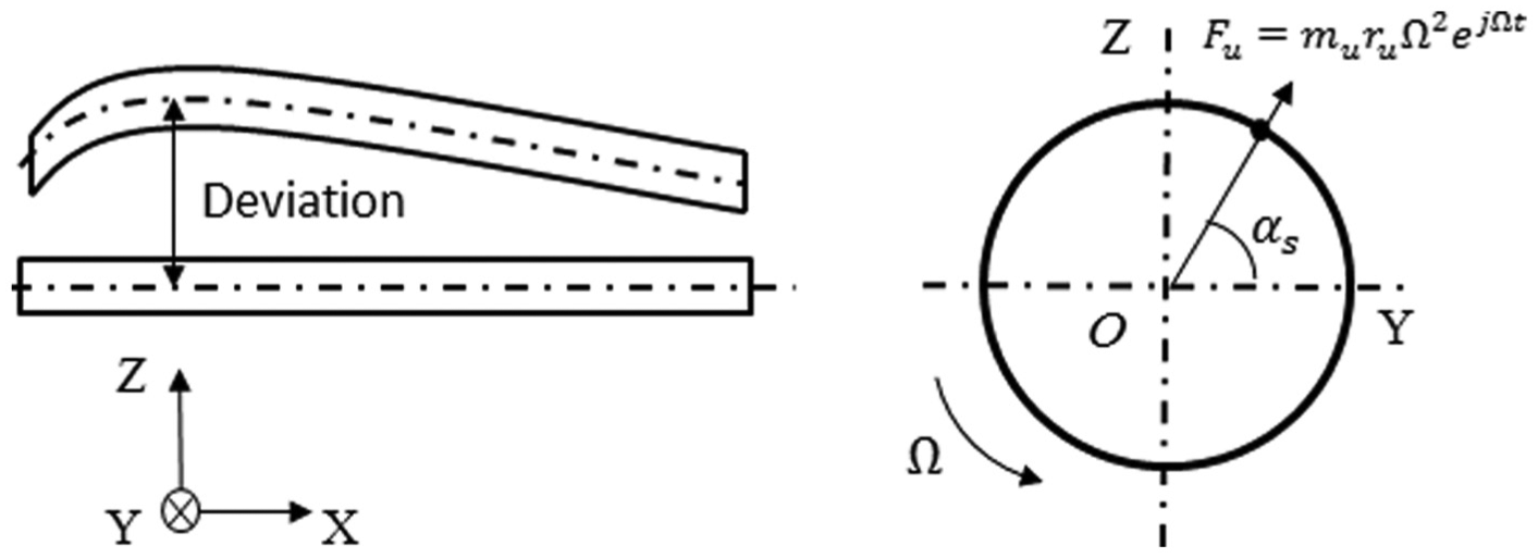
Shaft bending unbalance force.
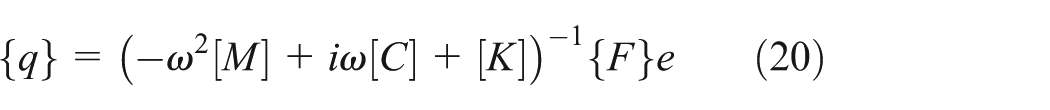
By solving the eigenvalue and eigenvector equations, the natural frequencies and mode shapes of the geared rotor system can be obtained. The steady-state response of the system can be achieved by applying the forced-vibration analysis in time domain.
Gear mesh dynamics model
The dynamics of gear systems have attracted the attention of many researchers and gained extensive studies in the past few decades. Özgüven and Houser 30 and Blankenship and Singh 31 made a comprehensive review of gear dynamic models. As mentioned before, the coupled effect between the gear mesh translational and torsional motion needs to be taken into account when analyzing the dynamic behavior of the geared rotor system. In addition, the gyroscopic effect is another factor to affect the gear dynamics. Therefore, a coupled torsional–translational gear dynamic model, which is shown in Figure 8, was developed including the gyroscopic matrices. The coordinate system of the proposed gear dynamic model is established so that the line-of-action is aligned in the Z-direction. The gear coordination system has to be transformed to the global coordinate system when the gear pair is coupled with the geared rotor system. The equations of motion for the gear mesh were obtained by using Lagrange’s formulation

where


Coupled gear mesh dynamic model.
The gyroscopic matrix can be written as

where
The eigen-equation is given by

The modal damping can be written as

Typically, the 5% uniform modal damping ratio is observed for the geared systems. It is well-accepted that the dynamics of the geared pair system is mainly excited by the TE and the corresponding dynamic mesh force is normally used to describe the severity of the dynamics of the geared rotor system. Hence, the formulated force vector for the proposed gear dynamic model is really a function of the magnitude of the TE, mesh stiffness, and the pitch radii, as expressed as follows

Then, the solution of equation of motion is given by
The static TE can be written as

where
The dynamic TE can be written as

Finally, the dynamic mesh force can be obtained as

Case study
To demonstrate the application of the proposed system model and evaluate the effect of shaft manufacturing bending deviation on the dynamic behavior of the geared rotor system, simulation on a typical one-stage geared system was conducted. Detailed information of the geared system components are listed in Tables 1 and 2. The four bearings are the same type and the supporting stiffness is equal to 3e4 N/m in both the Y- and Z-directions.
Shaft element data.

E = 2.1 × 10¹¹ Pa, µ = 0.3, ρ = 7800 kg/m3.
Gear data (disk).

Results of gear pair mesh dynamics
The dynamic gear mesh force under unit TE (1 µm) was calculated based on the aforementioned equations and the result is shown in Figure 9. The trend of the dynamic gear mesh force shows a general increase as the frequency increases. Also, there are two peaks around the frequency components of 88 and 722 Hz in the spectrum, respectively. The normalized modal strain energy results of these two peaks are shown in Figure 10. The DOFs of the strain energy plot can be found in equation (13). It is shown that the frequency component of 88 Hz is due to the contribution from the out-of-phase gear pair torsional mode and in-phase gear pair translational mode, and the frequency component of 722 Hz is dominated by the gear torsional mode and out-of-phase gear pair translational mode for the proposed gear model.

Dynamic gear mesh force (unit TE).

Modal strain energy (top: 88 Hz; bottom: 722 Hz).
Effect of magnitude of deviation
The bending deviation of a few samples of the example shaft was measured using the testing bench and the results show that the value of
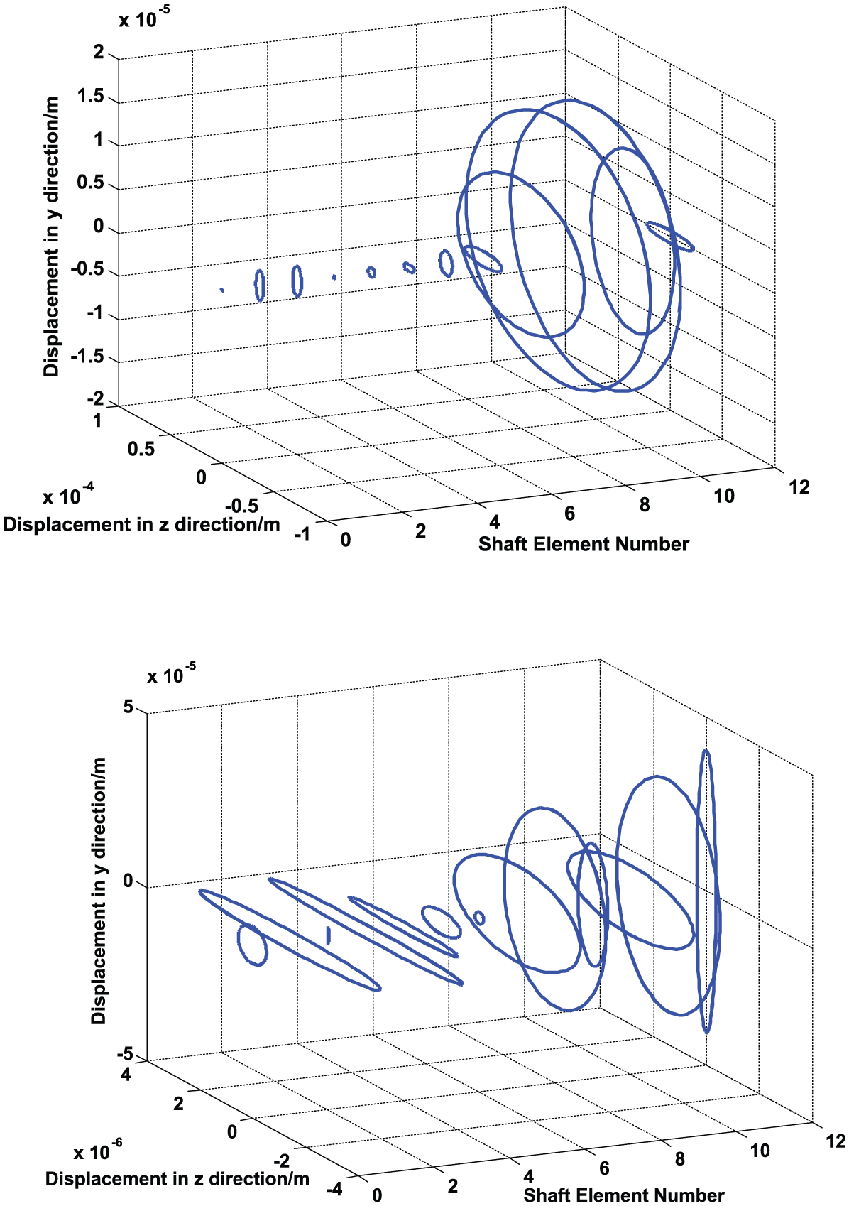
The effects of

Vibration response of bearing 2 (top: ru = 1 mm; middle: ru = 0.1 mm; bottom: ru = 0.01 mm).
Mode shapes of geared rotor system (top: 82 Hz; bottom: 184 Hz).
Effect of position of deviation
The position of shaft manufacturing bending deviation directive affects the location of the unbalance bending force. To evaluate the effect of the position of shaft manufacturing bending deviation on systematic dynamic response, the unbalance bending force (

Vibration response of bearing 2 under different deviation positions (top: shaft element 2; middle: shaft element 6; bottom: shaft element 11).
Effect of rotating speed (θ)
It is well-known that the rotating speed affects the dynamic behavior of the rotor systems including the geared rotor system. Besides this aspect, the rotating speed also affects the shaft bending unbalance force based on equation (16). To evaluate the effect of the rotating speed on the systematic dynamic response, simulation and analysis works were conducted under a large range of rotating speeds with keeping the magnitude and position of deviation constant. To be consistent, one typical result for bearing 2 is shown in Figure 14. As the shaft rotating speed increases, the overall vibration response of bearing 2 shows an obvious ascending trend. Also, the excitation frequency of the unbalance force gradually dominates the vibration spectrum of bearing 2 and this is due to the increasing magnitude of the unbalance force. The frequency component of 82 Hz shows less contribution for the 9000 and 12,000 r/min situations, while the frequency component of 184 Hz contributes more and more effect for the 9000 and 12,000 r/min situations. In addition, for 12,000 r/min case, new frequency component of 196 Hz appears in the vibration spectrum. The reason for the phenomenon is mainly because the natural dynamic properties of the geared rotor system are rotating speed dependent.

Effect of rotating speed on vibration response of bearing 2 (keys: dash dotted line —, 6000 r/min; dotted line ·······, 9000 r/min; dashed line –·–·–, 12,000 r/min).
Summary
A systematic modeling approach for evaluating the dynamic characteristics of geared rotor system with shaft manufacturing bending deviations is proposed in this article. The proposed method focuses on revealing the effect of shaft manufacturing bending deviations on the system vibration response, which is not much reported in the open literature. The data of shaft manufacturing bending deviation were measured using a shaft testing bench. The whole system was modeled using a coupled FEM with lumped parameter model, where the dynamic characteristics of meshing gear pair were represented by a coupled torsional–lateral gear dynamic model.
The computational results of simulation cases reveal that the natural frequencies of the geared rotor system, frequency components of dynamic gear mesh force, and frequency of excitation unbalance force appear in the vibration spectrum of bearings. As the magnitude of the shaft bending deviation increases, the overall systematic vibration response also shows an ascending trend. The magnitudes of most of the frequency components in the vibration spectrum increase as the deviation increases. Besides, as the position of the deviation changes, the system shows different dynamic sensitivities to the interested frequency components. Moreover, as the rotating speed increases, the overall system response also obviously increases and the frequency component of the unbalance force gradually dominates the spectra responses. As a next step, higher order shaft deviation should be considered in the analytical model and dynamic testing will be carried out to validate the proposed model.
Footnotes
Acknowledgements
This study was completed as part of the collaboration with the College of Engineering and Applied Science at the University of Cincinnati.
Academic Editor: Crinela Pislaru
Declaration of conflicting interests
The author(s) declared no potential conflicts of interest with respect to the research, authorship, and/or publication of this article.
Funding
The author(s) disclosed receipt of the following financial support for the research, authorship, and/or publication of this article: This study was supported by the Science and Technology Research Foundation of Chongqing (cstc2012gg-yyjsB0216, cstc2011ggB0030).