
Abstract
An experimental study on drilling of carbon fiber–reinforced plastic/titanium alloy was conducted using three kinds of drills to investigate the cutting process. This research was mainly focused on the drilling forces, drilling temperatures, chips, and delamination area with respect to the cutting parameters and tool geometries. One type of tungsten carbide twist drill and two types of chemical vapor deposition diamond-coated drills which were multi-facet drill and brad spur drill, respectively, were used in this research. The influence of drilling parameters and tool geometries was analyzed and the conclusions were drawn that the proper selection of drilling parameters and drill geometries could lead to better hole quality. Experimental results indicated that the drilling forces and hole quality have a strong connection with feed rate while the impact of cutting speed is small. Research results also showed that the use of multi-facet drill could reduce the delamination greatly and thus produced a better surface integrity. Besides, drilling temperature and titanium alloy chips were studied in this research.
Keywords
Introduction
Carbon fiber–reinforced plastics (CFRPs) are widely used in aeronautic and aerospace engineering owing to their characteristics of light weight, high specific strength, high specific stiffness, good fatigue resistance and corrosion resistance, and designability.1,2 Being the final link of aircraft structure assembly, drilling is the most frequently used process in composite materials machining. In aviation industry, most of CFRP laminates need to be assembled with other components by riveting and bolt connections, thus making drilling a necessary processing technique. 3 As CFRPs generally exist in the form of multidirectional layers, with the characteristics of soft and plastic matrix materials and high strength of carbon fibers, CFRPs are highly anisotropic materials. As a result of anisotropic characteristics, apart from traditional defects in metal machining such as dimension error, roundness error, and position error, there are still specific defects such as delamination, tearing, and uncut fibers at the drill entrance and exit in the drilling process. Moreover, fiber pull-out and matrix degradation can also be observed on the holes after drilling. These defects in drilling fiber-reinforced composites may lead to deterioration of the structure strength as well as poor assembly accuracy. 4 Thus, it is hard to control the machining quality in drilling process of CFRPs. Stacked composites of CFRP/CFRP, CFRP/Al, and CFRP/Ti are widely used in aircrafts such as Boeing 787 and Airbus A380. 5 In the final assembly step of aircraft manufacturing, 60% CFRP components are scrapped for their drilling delamination.6,7 Many authors have proposed that the delamination in carbon/epoxy machining is closely related to thrust forces which mainly depend on cutting parameters and drill geometry.8,9 In drilling process, different cutting parameters, such as cutting speed and feed rate, lead to different thrust forces and torques, hence affecting the quality of drilling holes.10–12 Therefore, delamination can be avoided effectively if the cutting forces generated can be kept lower than the critical thrust force by optimizing tool geometry and processing techniques, which are essential for achieving high-quality hole.
In the aspect of tool geometry, E Kilickap 13 proposed that the point angle of drill is a significant delamination factor and other machining defects, while both the delamination and surface roughness increase with the reduction in point angle from 135° to 118°. AT Marques et al. 14 carried out drilling experiments on CFRP using four different types of drills (twist drill, brad drill, dagger drill, and special step drill). Results show that the special step drill may result in a smaller thrust force and better processing quality, and drilling at the cutting speed of 53 m/min and the feed rate of 0.025 mm/rev with a pilot hole contributes to the prevention of delamination. EU Enemuoh et al. 15 presented that the drill with a point angle of 75° produced minimal delamination among drills with point angle ranging from 75° to 160°. Studies by W Chen 16 suggested that an increase in point angle led to an increase in thrust force and a decline in torque, while an increase in helix angle and chisel edge resulted in a decline in thrust force and torque. An experimental work carried out by H Hocheng and CC Tsao 17 with five distinct geometries of drills (twist drill, saw drill, candle stick drill, core drill, and step drill) on carbon fiber–reinforced composites shows that the core drill has the highest critical feed rate for inducing delamination, whereas twist drill has the lowest critical feed rate. AM Abrao et al. 18 conducted an experiment focusing on the effect of tool geometry on the thrust force and delamination of glass fiber–reinforced plastic (GFRP) drilling. Results indicated that the “Brad & Spur” drill with two cutting edges generated smaller thrust force values, while the drill with three cutting edges produced the larger thrust force. Furthermore, thrust force increased with an increase in feed rate, whereas the influence of cutting speed was small. In addition, it was concluded that there was no direct relationship between thrust force and delamination. Investigating the effect of tool materials and geometries, JP Davim and P Reis19,20 studied the drilling experiments on two kinds of drill materials and three geometries, that is, helical flute high-speed steel drill, helical flute carbide twist drill, and four flute carbide drill. It was concluded that the carbide drills presented less delamination during drilling and the helical flute twist drill produced less delamination compared to the four flute drill. CC Tsao 21 studied the experiments of core-saw drill in CFRP laminates and concluded that feed rate and drilling speed were the two most important factors affecting thrust force and delamination, and it was also concluded that thrust force reduced as the feed rate decreased. R Zitoune et al. 22 carried out the drilling experiments on CFRP/Al stacks and reported that the influences of drill diameter and feed rate on chip breaking were bigger than the effect of drilling speed owing to increased cross-sectional area of chips. The spindle speed of 2020 r/min and feed rate of 0.1 mm/rev should be chosen so as to achieve well-broken chips. Furthermore, feed rate has a greater influence on the circularity and surface roughness than spindle speed. Studies show that delamination factor decreases as cutting speed increases and feed rate decreases. 23 Feed rate has a greater effect on thrust force and push-out delamination in CFRP drilling. 24
A Koplev et al. 25 carried out experiment based on fast tool-off method and proposed that the chip-forming process of CFRPs was a material fracture process. Meanwhile, Koplev clearly pointed out that CFRP chips were formed by brittle fracture instead of plastic deformation. Due to its brittleness, the composites are inclined to induce brittle fracture, therefore chips produced by the composite materials are discontinuous and always in powder form. As to CFRP/Al laminate drilling, R Zitoune et al. 26 pointed out that feed rate had a significant impact on the shape of aluminum chips which would further affect the machining quality. Continuous metal chips may produce good surface quality, while entangled chips lead to damage on the hole surface of CFRP.
Due to the poor thermal conductivity of CFRP, the heat is accumulated inside the materials and cannot be conducted outside in time while drilling. Moreover, the processing temperature must not exceed glass transition temperature of resin. 3 Besides, owing to the low thermal conductivity of titanium alloy, the cutting heat produced in titanium machining is mainly transmitted by chips and cutting tools. 16 BS Rao et al. 10 presented that lower feeds and higher speeds may produce higher drilling temperature because of the low thermal conduction coefficient and the low transition temperature of composites. AM Abrao et al. 18 presented that the incorrect selection of tool geometries may lead to a high cutting temperature on account of friction between the clearance face of tool and the workpiece, and inappropriate selection of tool geometries could also result in higher surface roughness and delamination due to larger thrust force.
This article investigates the effects of drilling parameters and drill geometry on drilling forces and delamination in CFRP/Ti stacks. Moreover, real-time drilling temperature is measured and studied using a new-developed device so as to make the temperature be confined below resin glass transition temperature, which could make a good guidance in CFRP parts manufacturing.
Materials and methods
In this research, CFRP/Ti stacks were used as experimental materials. The CFRP composites made by hand lay-up have carbon fibers of T800 and epoxy matrix of X850, while titanium alloy was TC4 with hardness value of HRC35; the detailed parameters are shown in Table 1. The workpiece material size of CFRP was 300 mm × 200 mm × 6 mm, while for titanium alloy it was 300 mm × 200 mm × 3 mm. The drilling experiment was carried out in a DMU70V machining center with the maximum spindle speed of 12,000 r/min and 0.01 mm positioning accuracy. All the experiments were conducted without coolant liquid. Due to the different mechanical properties of CFRP and titanium alloy, variable feed technology was applied in this study. Drills used in this test were tungsten carbide twist drill and two types of chemical vapor deposition (CVD) diamond-coated drills which were multi-facet drill and brad spur drill, respectively, with all 6.35 mm diameter, as is shown in Table 2. The CFRP/Ti stacks were fixed at the center of the dynamometer as seen in Figure 1. In total, 16 sets of drilling parameters were designed for each drill in this experiment, which are shown in Table 3. The cutting speed of CFRP drilling varied from 50 to 140 m/min, while cutting speed of titanium alloy drilling was from 8 to 26 m/min, and the feed rate of both CFRP and titanium alloy drilling varied from 0.02 to 0.08 mm/rev. In this experiment, there were two brand new drills chosen for each type of drill; each drill was used to drill holes with parameters from set No. 1 to set No. 16 in Table 3, so each set of parameters were applied to drill 2 holes; then 32 holes were drilled for each type of drill and 96 holes were drilled in total, and the results achieved from each pair of holes were averaged to get final force and temperature for each type of drill under related parameters. And all the holes had been kept close to center of dynamometer to guarantee the measurement accuracy of drilling force and torque. As the drilling parameters for CFRP and titanium alloy were quite different, the drilling process had to be interrupted to lift up drills for parameters changing as soon as drilling out of CFRP.
Mechanical properties of CFRP and titanium alloy.

CFRP: carbon fiber–reinforced plastic.
Tool materials and geometries in the experiment.
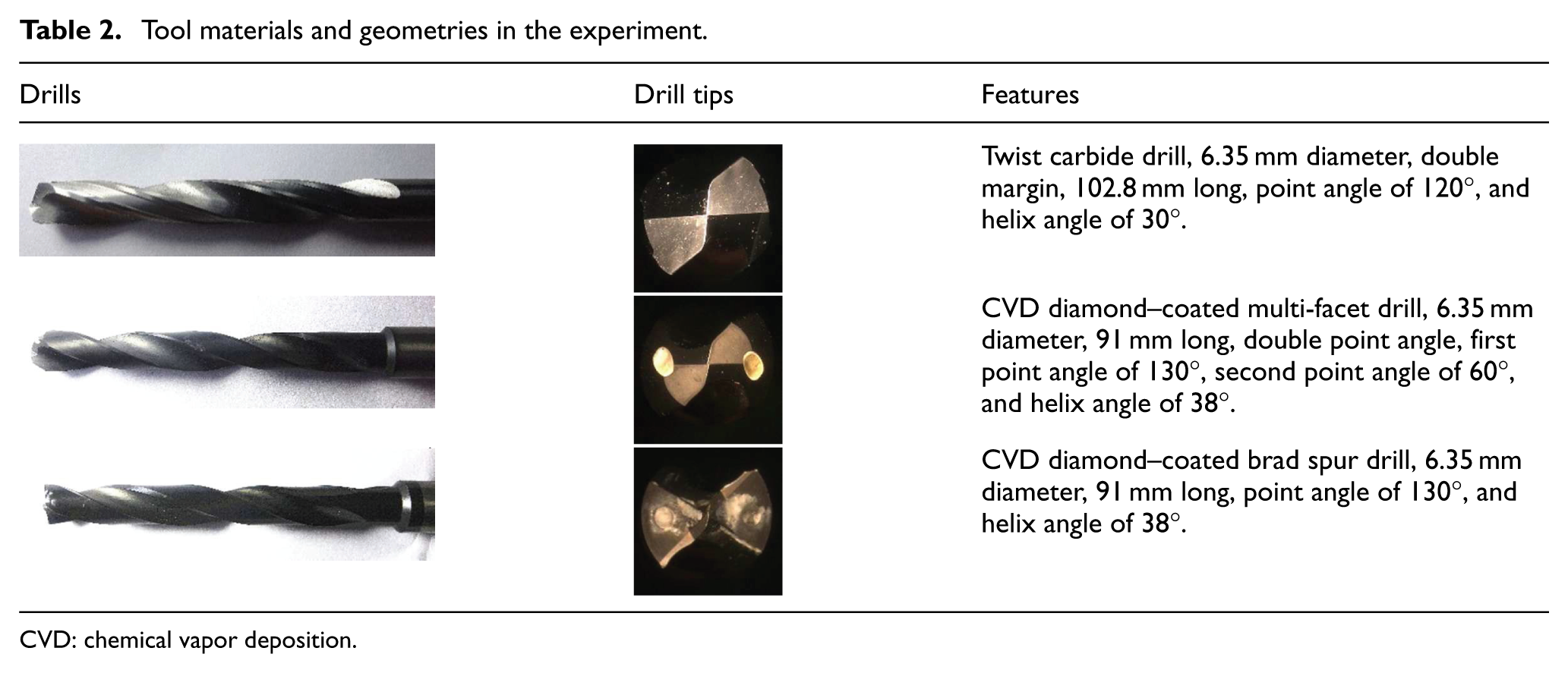
CVD: chemical vapor deposition.

Experimental set-up.
Drilling parameters design in the experimental work for each drill.

CFRP: carbon fiber–reinforced plastic.
The drilling forces during machining were measured with KISTLER9272 dynamometer and delamination areas were measured by KSI C-mode scanning acoustic microscope with scanning resolution of 0.1 µm. In addition, a new kind of temperature detecting device was developed, as demonstrated in Figure 2. Figure 3 shows the cutting temperature and cutting force measuring system in drilling process. The signal of dynamometer was sent to charge amplifier for pre-processing, the amplified analog signal was sent to data processing module for A/D conversion, and then the converted digital signal was sent to computer for final processing and recording, which can be shown in real time. Thermoelectric force generated by cutting heat was measured through two OMEGA-0.3 mm type-K thermocouples which have been pre-buried into drills through internal coolant holes; these two thermocouples captured real-time temperature of flank face during drilling and recorded the data into two storage modules, respectively, which were located in one specialized chassis as shown in Figures 2 and 3. The recorded temperature data could be extracted into computer later. As there was no coolant hole in twist drill used in experiment, no temperature had been measured for drilling process of twist drill.
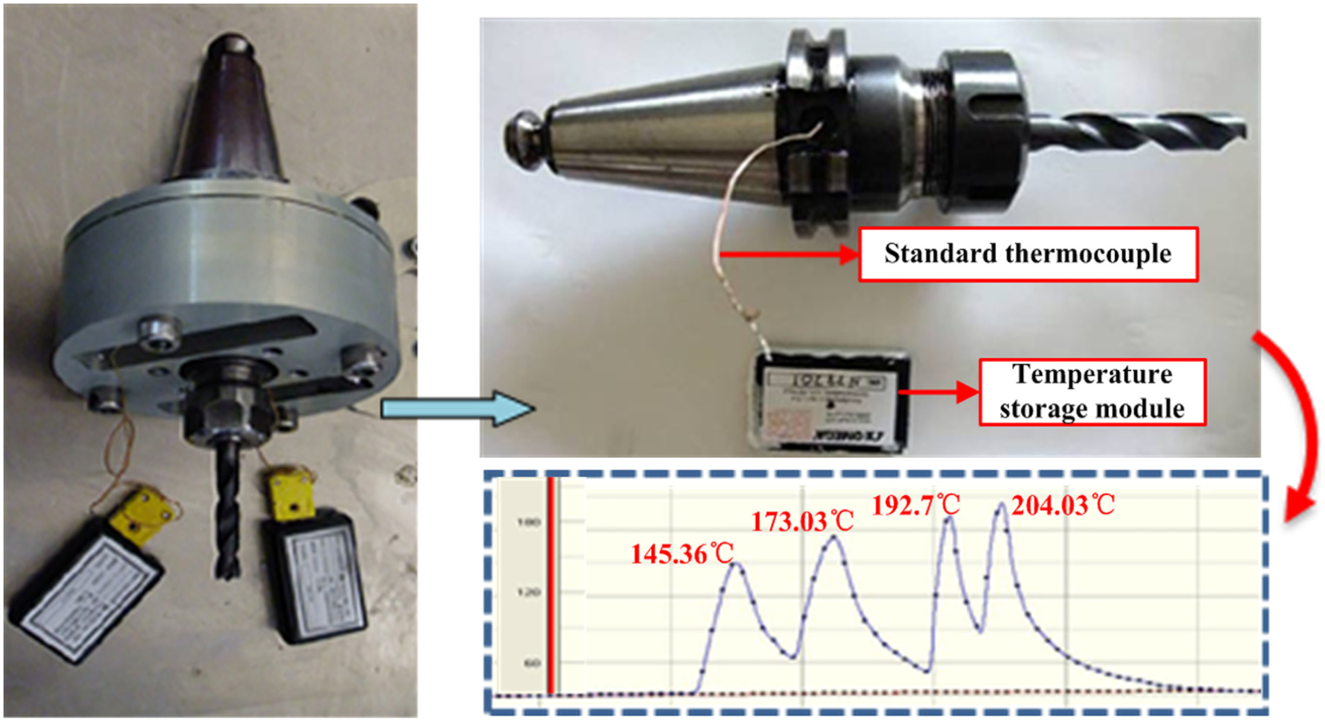
Cutting temperature measuring device.

Cutting temperature and cutting force measuring system.
Results and discussions
Effect of drilling parameters and drill geometry on drilling forces
The drilling forces (thrust force (F a) and torque (T)) are always considered to be a main factor that affects the machining quality and tool life during CFRP/Ti drilling. In this article, the influence of cutting parameters (cutting speed (v c) and feed rate (f)) and tool geometry on drilling forces was investigated using different kinds of drills. To evaluate the drilling force under same criteria and eliminate influence from CFRP/Ti boundary, all the values of drilling force were only taken from the stable interval in each drilling process, which was from bit wholly engaged till drill tip almost exiting, and the drilling force values were the average values of these stable intervals.
Figures 4 and 5 show the influence of cutting speed and feed rate on thrust force and torque when drilling CFRP/Ti using twist drill. It can be seen from Figure 4 that the thrust force is mainly affected by feed rate when drilling CFRP and titanium alloy stacks. It was observed that the thrust force increases with an increase in feed rate in both CFRP and titanium alloy drilling owing to an increase in cutting depth per revolution and thus the elevated shear area. The smallest thrust force was obtained at the feed rate of 0.02 mm/rev, while the biggest thrust force was at the feed rate of 0.08 mm/rev. Nevertheless, cutting speed has little impact on thrust force in titanium alloy drilling using twist drill, while the curves were almost coincided with each other, as shown in Figure 4(b). But as to CFRP, cutting force increases with elevated cutting speed. This may illustrate that matrix (resin) softening has not had much effect on CFRP properties since elevated cutting speed may cause an increase in cutting temperature as high friction coefficient of uncoated drill and thus lead to matrix softening. Because titanium alloy is very hard to drill, drilling temperature was much higher in titanium alloy drilling compared to CFRP drilling. The titanium itself and uncoated twist drill were softened at the same time during drilling process. As it was analyzed above, cutting force was insensitive to cutting speed if drilling titanium alloy with uncoated twist drill, which meant the thermal soften rate was almost the same between titanium alloy and uncoated twist drill. In addition, the influence rule of cutting parameters on torques is similar to the thrust force, that is, torques decrease gradually with the reduction in feed rate. As thrust force and torque are the key factors affecting machining quality of holes in CFRP/Ti drilling, a lower cutting speed and feed rate should be adopted in stack drilling process when using twist drill so as to achieve better processing quality.

F a in function of v c and f for twist drill: (a) CFRP and (b) titanium alloy.
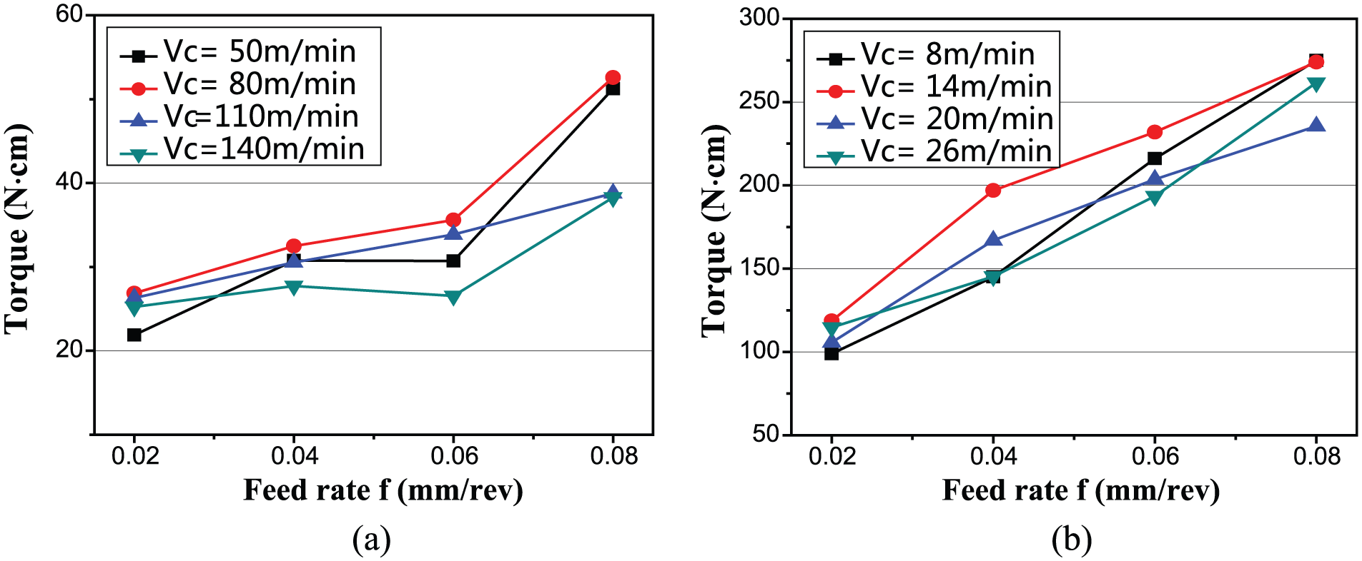
Torque in function of v c and f for twist drill: (a) CFRP and (b) titanium alloy.
With regard to the multi-facet drill, the impact of feed rate on thrust force and torque was similar to the twist drill. However, the differences lay in that thrust force was almost insensitive to cutting speed in CFRP drilling, while thrust force and torques decreased with an increase in cutting speed in titanium drilling, as is shown in Figures 6 and 7. As multi-facet drill was CVD diamond coated, the friction coefficient was lower on cutting face, which could help on lower cutting temperature a bit. Moreover, CVD diamond–coated drill had better thermal stability compared to uncoated drill, so sharpness of CVD diamond–coated drill was almost not affected by cutting speed, which was different than uncoated twist drill. As mentioned in the analysis of drilling with uncoated twist drill, the CFRP properties were not affected too much by cutting temperature. At the same time, cutting temperature could be even lower while drilling with CVD diamond–coated drill, and as shown in Figure 8, cutting temperature even decreased a bit with elevation of cutting speed. Then, it could be concluded that CFRP properties were almost not affected by cutting speed in the drilling process of CVD diamond–coated multi-facet drill. As to the analysis above, both CVD diamond–coated drill and CFRP properties were not affected by cutting speed, so thrust force was almost insensitive to cutting speed in CFRP drilling. As shown in Figure 8, cutting temperature increased with the elevation of cutting speed in titanium drilling with CVD coated multi-facet drill. As mentioned above, titanium would be softened under high cutting temperature, while CVD diamond–coated drill was with good thermal stability, so with the elevation of cutting speed, the thrust force would decrease as titanium got softer. In addition, thrust force and torque increased almost linearly with the feed rate which validates that feed rates play a dominant role in drilling force. For brad spur drill, the trend of drilling forces with feed rate was consistent with multi-facet drill (Figure 9).

F a in function of v c and f for multi-facet drill: (a) CFRP and (b) titanium alloy.

Torque in function of v c and f for multi-facet drill: (a) CFRP and (b) titanium alloy.

Drilling temperature using multi-facet drill: (a) CFRP and (b) titanium alloy.

Torque in function of v c and f for brad spur drill: (a) CFRP and (b) titanium alloy.
As far as the tool geometry is concerned, the three kinds of drills present different drilling processes. The drilling profile with set 10# parameters has been shown in Figure 10 to further investigate these differences. Take the classic twist drill for example based on Figure 10(a), the drills contacted CFRP laminated plates at point A and thrust force increased with the drilling process. The thrust force achieved the maximum when the main cutting edge was involved in drilling process wholly at point B. The thrust force had a short and continuous decreasing process from point B to point C due to thinner undeformed chip thickness. Then, thrust force maintained a stable process between points C and D. Finally, when the hole was drilled through completely, the thrust force became zero at point E.

Drilling process using three kinds of drills: (a) CFRP—v c = 110 m/min and f = 0.04 mm/rev, (b) titanium alloy—v c = 20 m/min and f = 0.04 mm/rev, and (c) drilling profile for whole drilling process.
The curve in Figure 10 shows the variation trend of thrust force with machining time after fitting through low pass filtering. As can be seen that the twist drill produced the largest thrust forces in CFRP and CVD diamond–coated brad spur drill generated the largest thrust force in titanium during drilling, which may bring into larger delamination in composite materials. Meanwhile, CVD diamond–coated multi-facet drill produced smooth and the smallest thrust force in both CFRP and titanium drilling, leading to a better hole surface quality and fewer drilling defects. Consequently, lower thrust force was recorded for the multi-facet drill in comparison with the other drills.
Multi-facet drill and brad spur drill could be taken as modification types of twist drill, furthermore, multi-facet drill is multi-flank twist drill and brad spur drill is twist drill with two more drill tips at circular edge. With more flanks, multi-facet drill divides the drilling process into several small processes and the point angles were changing between each process, as in our experiment, the drilling process was divided into two steps and point angle was changing from 130° to 60°, which made the drilling process more smooth and the drilling force smaller compared to twist drill with similar point angle. Brad spur drill has two more drill tips at the circular edge, which is an advantage to cut off carbon fiber, so the thrust force could be smaller compared to twist drill with similar point angle, but also as there are two more drill tips, contrary to multi-facet drill, the gradual drilling process of twist drill is integrated into a more aggressive process, more material is engaged into drilling at the same time, so the thrust force of brad spur was much higher than multi-facet drill in this experiment, while both of them were with same primary point angle. As to drill isotropic material, the aggressive drilling could make the thrust force from brad spur drill even higher than the similar twist drill. However, the two more drill tips do enhance the cutting ability along the circumference, which makes the torque from brad spur drill lower. Additionally, inconspicuous tool wear was observed after drilling 16 holes by each drill.
Effect of drilling parameters and drill geometry on drilling temperature
Drilling temperatures were measured using a kind of new-developed cutting temperature measuring device shown in Figure 2, and the drilling temperature values for each drilling process were the maximum temperature recorded for that process. Figures 8 and 11 show the drilling temperatures of multi-facet drill and brad spur drill in both CFRP and titanium alloy. Due to the lack of internal coolant hole in twist drill, thermocouples cannot be pre-buried; thus, no drilling temperature has been recorded for drilling process with twist drill. A decrease in CFRP drilling temperature was recorded when feed rate was elevated in both multi-facet drill and brad spur drill. This is due to that shear angle increases with the elevation of feed rate and thus friction coefficient decreases; moreover, cutting heat taken away by chips is elevated with an increase in feed rate. The effect of cutting speed on drilling temperature of CFRP was almost negligible. However, drilling temperature of titanium alloy increased with the elevation of feed rate and cutting speed on account of the augment of cutting depth and cutting power. Comparing the two kinds of cutting tools, multi-facet drill produced lower cutting temperature because of its larger contact area between cutting tool and materials which could give good heat dissipation. However, more materials were engaged in drilling process of brad spur drill at the same time, which produced more heat simultaneously to increase the temperature. Drilling temperature should be kept below 170°C in CFRP machining process, since glass transition temperature of epoxy matrix X850 is approximately 170°C. Otherwise, material strength decreases and the surface quality declines once the drilling temperature rises over the limit.

Drilling temperature using brad spur drill: (a) CFRP and (b) titanium alloy.
With the elevation of cutting temperature, materials will be softened, thereby less drilling force could be observed. But as can be seen from Figures 6(b), 8(b), 11(b), and 12(b), under the same feed rate, drilling force decreased at higher drilling temperature, but as the drilling temperature increased with feed rate in titanium drilling, the thrust force also increased. This phenomenon could be explained as below. Under the same feed rate, the material removed in each revolution was the same, so the cutting heat generated and thrust force required in each revolution should be the same if there was no material softening; as the cutting speed increased, the cutting heat generated in fixed time interval would increase, but cutting heat conducting out by workpiece at fixed time interval was almost the same, so the drilling temperature increased as more cutting heat accumulated, and the higher drilling temperature would transmit the heat to nearby titanium and soften it, which made the nearby titanium to be easily drilled and resulted in less thrust force in next revolution, and then reduced the overall thrust force. But under the same cutting speed, with increase in feed rate, the material removed in each revolution would increase, so the cutting heat generated and thrust force required in each revolution increased, then the heat accumulated in fixed time interval increased, which caused high temperature. There was also material softening caused by extra heat from more material removal, but the thrust force reduction by material softening was much smaller than the thrust force which increased due to more material removal in each revolution; therefore, the overall cutting force increased with an increase in cutting speed, along with an increase in cutting temperature.

F a in function of v c and f for brad spur drill: (a) CFRP and (b) titanium alloy.
Effect of drilling parameters and drill geometry on drilling chips
Tables 4 and 5 show the morphology of titanium alloy chips taken from the CFRP/Ti experiments at various feed rates and cutting speeds with three kinds of different drills. A better chip breaking is required during CFRP/metal stacks so as to avoid long chips scratching CFRP hole surface and reducing the quality of hole. It was concluded that better chip breaking could be obtained when the feed rate and cutting speed increased within tested experimental parameters. Most of the chips produced in this experiment were spiral and tight winded; when the feed rate was low, for example, 0.02 mm/rev, the shearing section was small and chips were fine, so chips can be winded easily and long continuous chips were formed; when feed rate increased, the shearing section became larger and chips became wider, so chips were hard to wind due to high stiffness and they started to break into small spiral pieces under 0.08 mm/rev feed rate. It can be noticed from Table 4 that the chips were winded tightly with higher kinetic energy with an increase in cutting speed, which could help in chip breaking, but this effect was not as significant as the effect of feed rate. The similar phenomenon as above has been seen in aluminum drilling in study by R Zitoune et al.22,26 It was shown in Table 5 that the chips from multi-facet drill were winded more straight due to its smaller second point angle. With the increment of feed rate, the chips from multi-facet drill formed a spiral tower, so the stiffness of chips increased which made them easier to break. As brad spur drill has three drill tips, it is not suitable for chip winding and chips from brad spur drill were relatively flat, which made them harder to break.
Titanium alloy chip morphology using twist drill.

Titanium alloy chip morphology using three kinds of drills (v c = 20 m/min).

From the angle of cutting tool design, chip-breaking slot of flank face could make the titanium alloy cut off better during drilling, thereby avoiding chips entanglement. Additionally, the sharp drill tip makes work materials in the state of shear condition rather than squeezing condition in order to remove the materials better. From the aspect of cutting tool materials, high-strength and wear-resistant materials are preferable. With the purpose of reducing the friction coefficient and improving the heat conduction, CVD coated materials are more suitable for cutting tools.
The feed rates have a larger impact on chip breaking due to increased cross-sectional area of chips as feed rates are elevated, and the cutting speed has a smaller effect on formation of cutting chips. The cutting speed of 20–26 m/min and feed rate of 0.06–0.08 mm/rev should be chosen so as to achieve well-broken chips
Effect of drilling parameters and drill geometry on delamination
Tables 6–8 show the delamination damage on the CFRP caused at the drill entrance. Since titanium alloy could be regarded as backing materials and thus delamination and burr damage at the CFRP exit was small due to the increased stiffness of CFRP materials, only delamination damaged at the drill entrance has been analyzed. Three drill geometries (twist drill, multi-facet drill, and brad spur drill) were tested at various cutting speeds and feed rates. In this article, two-dimensional (2D) delamination factor has been applied to quantitatively evaluate delamination; the delamination factor can be described as below
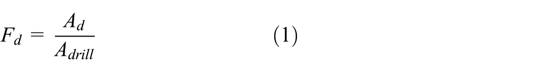
where
Graphs of the delamination observed in drilling CFRP using twist drill.

CFRP: carbon fiber–reinforced plastic.
Graphs of the delamination observed in drilling CFRP using multi-facet drill.

CFRP: carbon fiber–reinforced plastic.
Graphs of the delamination observed in drilling CFRP using brad spur drill.

CFRP: carbon fiber–reinforced plastic.
As can be seen from Tables 6–8 and Figure 13, feed rates play the most important role in delamination area at entrance, while the effect of cutting speeds is small; the delamination area at entrance increases with an increase in feed rate, and as to twist drill and brad spur drill, the delamination area would suddenly increase a lot after feed rate is over a critical value. And there is no clear relationship which can be derived from delamination area and cutting speed. The best machining quality was achieved when the feed rate was 0.02 mm/rev and cutting speed was 50 or 80 m/min. Besides, obvious tearing delamination was not observed during multi-facet drill machining as its smooth drilling process and poor machining quality were obtained when using brad spur drill for its aggressive drilling process. Serious tearing delamination was found especially when feed rates of 0.06 and 0.08 mm/rev are applied to drilling. For the lowest feed rate of 0.02 mm/rev, delamination at entrance cannot be prevented either.

Delamination factor at entrance under different drilling parameters: (a) twist drill, (b) multi-facet drill, and (c) brad spur drill.
Conclusion
In this study, the effects of cutting parameters and tool geometry on drilling forces, drilling temperature, chips, and delamination in CFRP/Ti stacks were investigated using three different drills and various feed rates and cutting speeds. The conclusions can be drawn as follows:
The drilling force (thrust force and torque) was affected by drilling parameters, especially the feed rate. Drilling forces increased with the elevation of feed rate, but had uncertain interactive relationships with cutting speed. As to uncoated drill, thrust force which increased with the elevation of cutting speed in CFRP drilling was almost insensitive to cutting speed in titanium alloy drilling. However, opposite behavior has been observed when drilling with coated drills.
As to the drilling temperature, it decreased with elevation of feed rate in CFRP drilling, but it increased with elevation of feed rate in titanium drilling. Drilling temperature was almost insensitive to cutting speed in CFRP drilling, whereas it increased with elevation of cutting speed in titanium drilling. Compared to brad spur drill, multi-facet drill produced lower cutting temperature.
Cutting chips in titanium drilling were spiral and tight winded for all three drills, but the chips from multi-facet drill were winded more straight and similar to spiral tower, while the chips from brad spur drill were relatively flat as it has three drill tips which made it hard to wind chips. The chips became wider with elevation of feed rate due to larger shear section, which made it easier to break the chips. And with elevation of cutting speed, chips were winded tightly with higher kinetic energy, which could help in chip breaking, but the effect of cutting speed on chip morphology was much smaller than the effect from feed rate.
Delamination area can be reduced with lower feed rate and delamination will suddenly increase a lot after feed rate is over a critical value. Brad spur drill presented the worst machining quality among the three drills with large area of tearing at the feed rates of 0.06 and 0.08 mm/rev and multi-facet drill presented the smallest delamination area at the feed rates of 0.02 mm/rev.
A new temperature measurement device was developed and can be used in detecting real-time cutting temperature within flank face in order to make the cutting temperature be confined below glass transition temperature in CFRP drilling, which was 170°C in the experiment. And the maximum recorded drilling temperature of multi-facet drill and brad spur drill were around 110°C and around 125°C, respectively, in this experiment.
Footnotes
Academic Editor: Neal Y Lii
Declaration of conflicting interests
The author(s) declared no potential conflicts of interest with respect to the research, authorship, and/or publication of this article.
Funding
The author(s) disclosed receipt of the following financial support for the research, authorship, and/or publication of this article: This research is supported by National Natural Science Foundation of China (No. 51475298 and No. 51105253).