
Abstract
The work presented in this article demonstrates the use of an empirical and simplified approach based on an optical technique and a home-made ad hoc code that give knowledge of the shape and falling velocity of a free-falling non-submerged liquid stream to predict its typology and flow rate. The visualization photographic technique is a non-intrusive robust technique which can be applied to high-temperature liquids in harsh environments, such as an iron stream in a foundry. This technique allows predicting the liquid stream boundaries and contours without any type of treatment on the fluid. As a result of employing this empirical methodology, three flow typologies for a water stream are proposed and demonstrated experimentally. Comparisons with experimental data reveal satisfactory estimations of mean flow quantities. Finally, the approach used based on experimental visualization is carried out in an iron stream of a foundry, not being disruptive to in-situ foundry operations and showing its potential to improve performance of the cast parts’ properties during the casting phase and revealing to be a useful tool for process optimization.
Introduction
The cast iron foundry industry produces cast parts for automotive, agriculture, transportation, energy, aerospace, and manufacturing industry. All foundry processes generate a certain level of rejection, lost irrecoverably, that is closely related to the type of casting, the processes used, and the equipment available. As the quality demands from end users of castings increase, it is essential that cast iron technology moves forward together with green manufacturing as a first step toward sustainability.
Extensively, work has been carried out by foundry community to minimize the casting defects, such as porosity, slag, and clogging, but only few literatures are concerned with the casting of the metal itself which is related to a more versatile melt control technology.
The flow control system in a tundish has a significant impact on the quality and level of rejection on the pouring of the castings. 1 If the metal does not flow in a consistent stream, it could result in casting defects from oxidation, air entrapment, and erosion of the pouring mold, among others.
Much of the understanding of the relationship among stream shape, flow conditions, and casting properties relates to human visual control in the pouring of the casting. A main goal of this work is to achieve a better knowledge of the stream shape and flow conditions that will improve the integrity and consistency of the metal flow into the mold.
The physics of liquid jets in applications or academic situations such as the jet breakup, critical limit, jet dispersion, fragment sizes, and drop shapes is of great interest from fundamental to technological aspects.2,3 A quite extensive literature to review regarding jets’ characteristics to processes such as atomized sprays, jet cutting, jet cleaning, and fuel injectors, among others, can be found. Concentrating exclusively on vertical liquid jets, these studies mainly deal with the plunging jet flow patterns, entrained air bubble sizes, and the influence of the jet velocity and variations of jet falling lengths on the jet penetration depth. Contrariwise, a cast iron stream differs significantly from those studies.
Jeffrey et al. 4 presented a method to predict the velocity decay of a free-falling jet into a plunge pool. A model of a plunging jet was constructed to simulate a free-falling fully air entrained developed jet and a non-aerated undeveloped jet. The velocity decay data were collected by means of a pitot tube and the air entrained by means of an air concentration probe. Despite being a free-falling jet, it was rectangular in shape and intrusive techniques were used. Therefore, it must be discarded in a cast iron stream.
Non-invasive visualization techniques are widely used for the examination of the flow fields, such as particle image velocimetry (PIV) and time-resolved particle image velocimetry (TR-PIV), which introduce tracers, and they are chosen in such a way that their movement represents the movement of the fluid.5,6 Melling 7 demonstrated that proper flow seeding is particularly critical with PIV. Experimental investigations were performed to investigate the flow-field structure on a submerged water jet impinging normally on a smooth quiescent and flat surface and the geometry in a submerged entry nozzle in a water model.8–10 Jiang et al. 11 presented the advanced applications of PIV technique to measure the flow field of different axial planes, axial time-average velocity, and the length of the initial sections of horizontal low-pressure jet flows emitted by the sprinkler with different nozzle geometric parameters and working pressures. A sophisticated multigrid cross-correlation digital particle image velocimetry (MCCD-PIV) is used to investigate the stability and structure of low Reynolds number axisymmetric jets to a qualitative examination of the development of the jet. 12 Gong et al. 13 conducted a visualization method to capture the micro-surface wave in a high-speed vertical jet characterizing diverse wave patterns. However, these studies are not concerned with non-submerged driven by gravity jet in the atmosphere and even less with regard to high-temperature cast iron stream in real and practical working conditions in a commercial foundry.
Moreover, the air entrainment within the liquid stream limits the optical methods such as PIV. One natural limitation is that the presence of phase boundaries in multiphase flow blocks the optical path to the measurement location. 14 Subsequently, to overcome this phenomenon, visual techniques can be used. A combined experimental and numerical investigation is carried out by Qu et al. 15 Bubble sizes were estimated from single images by means of image processing through subsequent background subtraction, cell segmentation, bubble detection, and bubble size calculation. A similar technique is carried out to visualize the random motion of a single bubble and to obtain empirical relationship between penetration depth and air entrainment rate.16,17
Conversely, a cast iron stream differs significantly from the studies presented above. As far as authors’ knowledge, there is still a lack of studies concerning the shape prediction and flow rate estimation of a free-falling non-submerged vertical casting iron stream driven by gravity in the atmosphere from the tundish nozzle exit to the mold. Summing up, the tracer particles in the PIV technique cannot be used in a cast iron steam at 1450°C and also applies to intrusive techniques. As a matter of fact, to overcome the main drawbacks of cast iron, it is not necessary to obtain a very precise quantitative description of the liquid velocity vectors in an iron stream. 18 Furthermore, the dimensions of the nozzle exit and the mean diameter of the liquid stream differ considerably from the liquid jet applications reported, and the influence of the air entrainment into the stream cannot be neglected.
Due to that, the keystone of this work is that an empirical and simplified approach based on an optical technique gives knowledge of the shape and falling velocity of a vertical liquid stream that will be very useful to predict reasonably its flow condition and flow rate. As a bottom line, this methodology has a great field of application and can be implemented in a real cast iron stream on a current foundry. The approach used based on experimental visualization and home-made ad hoc code could lead to an improving performance of the cast parts’ properties during the casting phase and can be considered as a useful tool for process optimization.
Materials and methods
There are significant differences between water and cast iron; as fluid properties, the most notable differences are density and surface tension, and as operating conditions, fluid temperature. However, water and cast iron have similar kinematic viscosity that together with the difficulty of real industrial condition experiments have led dynamic water modeling in partial-to-full scale models a universally accepted method for observing and evaluating flow conditions of molten metals achieving notable results and quality improvements.
Using a water model simulates experimental investigations on a cast iron stream driven by gravity in the atmosphere from the nozzle exit of the tundish. The experimental apparatus consists of two independent units, the fluid cycle and the visualization system.
Experimental setup
The fluid cycle consists in a full-scale foundry pour box (1, see Figure 1) constructed using poly(methyl methacrylate) (PMMA). A centrifugal pump (2) feeds the pour box through a filter (3) and flow rates are adjustable by a valve (4) mounted on the pipe (5) between the pump and the pour box. It can also maintain a constant water height while casting by means of an overflow pipe (6). The pour box is fitted with a replica stopper rod (7) and slender nozzle (8), also fabricated of PMMA. The stopper rod can be closed on the top with a rubber plug (9) avoiding the air to enter through its interior, which allows simulating non-ideal casting conditions afflicted with typical slag build-up in the stopper rod plugging it. The nozzle exit of radius R0 = 13 mm (at z = 0, see Figure 3) leads the liquid stream (10) into the static air with a maximum falling distance of 750 mm, where gravitational forces drive the stream to a reservoir (11) with negligible influence of air friction and air movement.
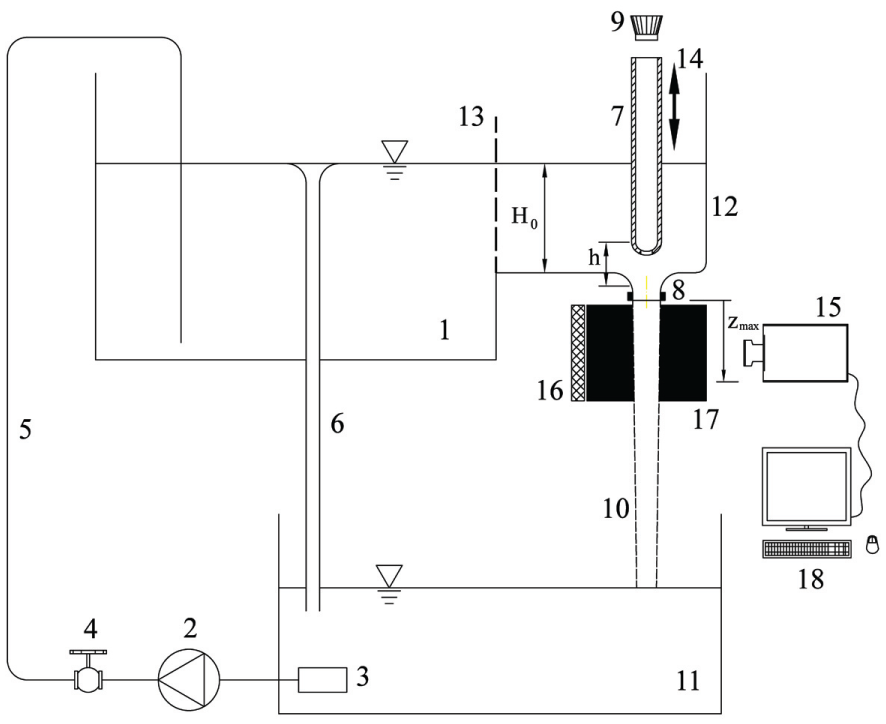
Sketch of the experimental setup.
The main dimensions of the model are as follows: the tank of 500 × 500 × 400 mm3 and the pour box with a prismatic shape (1) of 300 × 250 × 250 mm3 and ∅250 × 250 mm2 being the exit part (12) where the nozzle is located. Between them a wire screen flow tranquilizer (13) is placed to breakup and straight the flow. The maximum capacity is 150 L of water, for which the temperature is measured. A fully automated-operated lift-actuation mechanism (14) is used to seat and unseat the stopper rod in the nozzle to simulate openings and shutoffs and also establish the constant stopper rod elevation h during the casting. The experimental flow rate is calculated by means of filling a volume on a precision scale and continuously recording the fluid weight exiting from the nozzle.
The stream shape formation was observed experimentally by the visualization system consisting on a high-speed video camera Photron Ultima APX-RS (15) with 17.5 µm pixels in a 1024 × 1024 pixels sensor able to run 3000 fps at full resolution and 250,000 fps at limited resolution. The images were obtained with maximum resolution, that is, 1024 × 1024 pixels at 500 and 1000 Hz with a 105 mm objective. The buffer memory of the camera allows recording up to 2048 images per experiment, with duration of slightly more than 4 and 2 s, respectively.
With regard to illumination, a modification of the backlighting is applied: the sidelit. The background is a black opaque sheet (16) and a directional light from the side through a white styrene sheeting sheet (17) creates a diffuse and clean light on the stream. The sidelit arranges the light in such a way that it leaves the darkness behind the stream so that very well illuminated edges and area are achieved. The collected digital images are processed and analyzed on a computer (18).
Test fluid
The test fluid is ordinary tap water at temperature 20°C with density ρ = 998 kg m−3, viscosity µ = 1 mPa s, and surface tension σ = 73 mN m−1; no other substance is added to the water.
Experimental methodology
The height from liquid free surface to nozzle exit remains constant during all the experiments at the value of H0 = 230 mm (see Figure 1). Then, maximum theoretical velocity at the nozzle exit is U0 = 2.1 m s−1 (see Figure 3), achieving a recording of slightly more than 4 s of the vertical liquid stream at Nfps = 500 fps with maximum resolution.
A millimeter ruler was placed in the plane of the stream for calibrating the distance in the images obtaining a relation pixel to millimeter of Npxmm = 14 px/mm. The estimated maximum vertical displacement of the stream is zmax = 73 mm (see Figure 1) with an estimated average time to go out of images of 0.0365 s = 18 frames, considering it an acceptable precision based on the maximum theoretical velocity and tests performed.
Visualization photographic technique
From the grey-scale digital images in TIFF format (0: black ÷ 255: white), the stream contour and edges information can be extracted by the use of a steepest image-processing grey-scale gradient methodology that authors have named visualization photographic technique (VPT). The stream edges can be determined within an uncertainty of about 1 pixel at a total contour of 700 pixels.
The VPT methodology is described as follows (see Figure 2):
The sidelit provides a diffuse and clean light on the stream which is digital recorded in a frame image.
The TIFF digital image is read, cropped out, and masked the areas out of interest.
A histogram of intensity values of the image shows the intensity levels that allow setting up the threshold for the segmentation.
The resulting image is dilated and eroded with a disk-shaped filter in order to define edges boundaries of the stream.
The detected boundaries must be selected and divide in two parts, left and right hand side contours.
Pixel coordinates are computed to calculate the stream width in all its falling height and coordinates are transformed from image space (pixel values) to space coordinates.
Statistical evaluation, plots, and videos are processed for all the images of the corresponding experiment.

VPT procedure on a free-falling water stream.
Jet dynamics
When a liquid pours vertically from an outlet into stationary air, a free-falling non-submerged vertical liquid jet is formed, initially of constant radius that accelerates, stretches, and narrows under the influence of gravity. The stability of the jet is mainly subjected to effects of gravity, surface tension, viscosity, and inertial effects.
Plateau 19 first characterized this stability in 1873 through experimental observation, and he noted the instability arose when the liquid column length exceeded the column diameter by a factor of about 3.13, which was later corroborated by Lord Rayleigh. 20
Jet shape function and stability
The theoretical characterization of a jet shape has been of significant interest of study by many researchers owing to its application on engineering practice. In this article, based on Massalha and Digilov’s 21 work, the theoretical problem of a free-falling non-submerged vertical liquid stream as isothermal, laminar and incompressible Newtonian fluid of density ρ, viscosity µ, and surface tension σ injected vertically downward (following the direction of gravity, g) into stationary air with mean velocity U0 from a circular nozzle orifice of radius R0 is addressed (see Figure 3).

Sketch of the fluid jet.
Here, the effects of the gravity, the surface tension, and the viscosity in comparison with inertia are represented by the Froude number (Fr), the Weber number (We), and the Reynolds number (Re) as

The Bond number (Bo), defined as

where
At large Bo, when the surface tension effect becomes negligible compared to the gravity, the gravity and the viscous resistance govern the jet. Moreover, the viscosity relative to gravity becomes negligible to

Together with the jet shape, the stability of the liquid jets plays an important role. Viscous jets, existing slowly from a circular nozzle, are dominated by viscous forces upstream and by inertial forces downstream. Furthermore, the source of instability can also be attributed to surface tension, flow rate, and nozzle diameter and configuration. With regard to the transition from jetting to dripping, Le Dizès
22
showed that if the basic falling capillary jet in the limit has approximately an axisymmetric plug profile and
Jet shape description
In the liquid stream studied in this work, nozzle diameter, stream radius, height, and velocity are quite far from the jets encountered in the previous works. The data of our configuration are used to calculate the critical parameters with experiments with slow velocities under 1 m s−1. 24 Moreover, the stopper can be plugged or unplugged, allowing entering air into the stream.
The shape and stability of liquid jets of great but finite radius and length drawn down by gravity remains unmentioned in the literature on jet dynamics. Here, the dimensionless group numbers computed from equation (1) are Fr = 17.7, We = 1604, Re = 55121, Bo = 90.7, and
Convincingly, this work has converged to experimental work, which provides the stream diameter as a function of length calculated using the digital images with the home-made ad hoc MATLAB® code programed by the present authors. Additionally, the characteristics of the nozzle orifice radius, stream radius, and length are indirectly included in the stream shape and then, an empirical methodology to estimate the flow rate using the falling velocity is derived which agrees moderately well with the experimental data.
Results and discussions
This section explores the significance of the results of this work.
Water stream shape and stability: empirical methodology
The empirical methodology to the water stream shape was applied to Nim = 900 images, being approximately 50 cycles of the maximum vertical displacement of the stream, which was proved to have sufficient accuracy. It is not the aim of this work to perform neither a comprehensive experimental study on the stationary stream shape nor an experimental stability model.
Three different constant positions of the stopper rod elevation have been studied: h = 1 mm, h = 3 mm, and h = 6 mm. They have been chosen as the most representative shape and stability modes and typologies of the water stream as a function of stopper rod elevation. Besides, for each elevation, two cases are performed: with rubber plug (no air through stopper rod interior) and without rubber plug (allowing air through stopper rod interior) to experimentally simulate the clogging of the stopper rod during casting iron operation.
Figure 4 superimposes the evolution of the width contour (stream diameter) of the water stream when falling from the nozzle to the maximum vertical displacement for all images. The stream height has been normalized with the maximum vertical displacement and the stream width with the nozzle diameter. Figure 4(a), (c), and (d) shows the great influence of the stopper rod elevation on the performance of each water stream. As the elevation increases, the stream diameter becomes wider and unstable with the falling distance.

Evolution of the width contour (stream diameter) of the water stream when falling from the nozzle to the maximum vertical displacement for all images for the three stopper rod elevations, with and without plug: (a) h = 1 mm without plug, (b) h = 1 mm with plug, (c) h = 3 mm without plug, (d) h = 3 mm with plug, (e) h = 6 mm without plug, and (f) h = 6 mm with plug.
Figure 4 also shows a blue dashed and dotted line, which is the jet shape function of equation (2). Within all range of elevations, a narrowing occurs just at the exit of the nozzle. However, an important expansion occurs at 1 mm elevation, and at 3 and 6 mm elevations the stream approaches the jet shape function. This tendency is corroborated in Figure 5 at three different stream vertical positions (initial z = 0, half z = zmax/2 and final z = zmax) and its mean value.

Evolution of the width contour (stream diameter) of the water stream at initial, half, and final vertical displacement for the three stopper rod elevations with plug: (a) h = 1 mm with plug, (b) h = 3 mm with plug, and (c) h = 6 mm with plug.
The presence of this expansion is owing to the flow conditions generated between nozzle and stopper rod section that causes the entrainment of air to the interior of the stream in its free-falling trajectory. At the elevation of 3 mm, the good agreement occurs for the no-plug configuration with the theoretical jet shape, despite the width contour scatter as it depicts in Figure 6. An example of the importance of the influence on the typology of the stream is shown in Figure 7 by means of histograms.
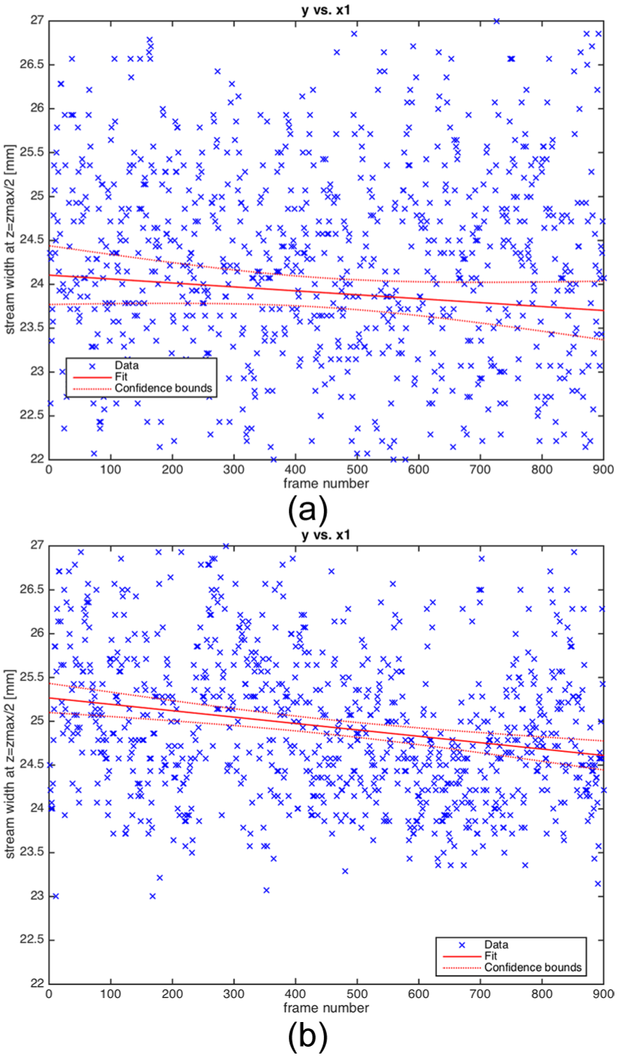
Scattering of the stream width at half vertical displacement (z = zmax/2) with plug: (a) h = 3 mm with plug and (b) h = 6 mm with plug.

Histogram of the stream width at half vertical displacement (z = zmax/2) without plug: (a) h = 1 mm without plug: annular cross section typology and (b) h = 6 mm without plug: circular cross section typology.
Water stream flow rate estimation: experimental validation
An experimental validation of the VPT is to estimate the flow rate by means of the presented empirical methodology based on a simplified approach described as follows:
Find the maximum width contour of the stream all over its height (z = 0 ÷ zmax) for each frame image.
Calculate the number of vertical pixels between two consecutive maximum width contours. This number of vertical pixels will be used to evaluate the time of falling between two consecutive maximums of the width contour of the stream.
Calculate the mean value of the number of vertical pixels Npx per frame image.
Estimate the free-fall velocity as
Calculate the mean of the width contour of the stream all over its height (z = 0 ÷ zmax) for each frame image, being an estimation of the diameter of the stream.
Estimate the cross-sectional area of the stream as a circular section.
Estimate the flow rate of the stream as the multiplication of free-fall velocity and the area of the stream.
Figure 8 depicts the flow rate estimation for the six experiments performed, summarized in Figure 4 and normalized by the theoretical flow rate.

Flow rate quantities estimation.
This experiment demonstrates the capabilities of the presented empirical methodology to predict flow rate and shows the differences in performance of the water stream as a function of the stopper rod elevation, mainly regarding to air entrainment. The elevation of 1 mm without plug presents the maximum error on flow rate estimation, around 72% as it is depicted in Figure 9. As previously demonstrated, this configuration entrains air to the center of the stream turning into an annular cross section. Hence, the width contour as stream diameter to estimate the flow quantities drives to an important error. However, this error is not useless, on the contrary, it has a critical significance: it must be taken as an alarm in the in-situ casting process because the iron mass flow from the tundish would not fulfill the corresponding mold and, consequently, the casting parts will be rejected.

Relative error on flow rate estimation versus stopper rod elevation, with and without plug.
However, this error becomes minor as the stopper rod height increases as shown in Figure 9. The elevation of 6 mm, with and without plug, is the best configuration once the influence of the stopper rod is negligible and the nozzle becomes the slot of a gravity-driven stream issuing the pouring box.
Casting iron stream characterization: practice development
The main difference in iron stream properties, besides the temperature, is its surface tension. Data of the surface tension of cast iron have been proven experimentally, and values between 990 and 1465 mN m−1 are obtained as a result of its relationship with the graphite shape. 25
The empirical methodology to the iron stream shape was applied on real images from the optical sensing system on a foundry. This system is used to late-steam iron inoculation and also to visual inspection of the continuous casting flow rate by manual control of the stopper rod elevation. The VPT and the empirical methodology are applied to the real images to identify the iron stream boundaries and contour, as it is shown in Figure 10.

VPT procedure on a casting iron stream.
Currently, the optical sensing system allows a maximum of 19 images per mold, which is proved not to have enough accuracy, as is it is depicted in Figure 11. The aim of this work is to perform neither a comprehensive experimental study on the stationary stream shape nor an experimental stability model of an iron stream, but to show the potential of the proposed approach to setup on casting iron stream quality.

Evolution of the width contour of the iron stream at initial, half, and final vertical displacement.
Conclusion
An empirical methodology experimentally validated to characterize the shape and estimate the flow rate of a free-falling non-submerged liquid stream has been presented. The VPT is well-suited as a non-intrusive technique that allows predicting the liquid stream boundaries and contours without any type of treatment on the fluid and independent of its temperature. As a fruit of these measurements, the results lead to three typologies of the water stream:
Annular cross section typology. Maximum influence of the low stopper rod elevation. The narrowed section between nozzle and stopper rod, and the air entrainment into the interior of the stream drive the stream in its free-falling. The influence of the stopper rod with and without plug is also critical.
Contour shape instability typology. Combined influence of the stopper rod and the nozzle at medium stopper rod elevation. A quasi-stationary periodic instability on the boundaries of the stream in its free-falling is presented. The influence of the stopper rod with or without plug loses significance.
Circular cross section typology. Maximum influence of the nozzle at high stopper rod elevation. The nozzle drives the free-falling characteristics of the stream and no air is encountered. The influence of the stopper rod, with or without plug, is negligible.
With regard to the plug cases, the configuration with plug presents less flow rate estimation error for low stopper rod elevation (50%) compared to the configuration without plug (72%). However, the low stopper rod elevation is a transitory flow configuration on casting iron in a foundry, which means that this error on the flow rate estimation to this elevation turns out to be of less importance. As the stopper elevation increases, this error becomes much smaller without plug (2%) than with plug (13%). Keeping in mind that the configuration with plug simulates the real clogging stopper rod, it means that special care must be taken in the foundry with the stopper rod containing slag.
Whether this empirical methodology holds for casting iron stream or not is demonstrated with the presented empirical methodology. Nevertheless, more experiments have to be performed with an improved optical sensing system on the foundry to obtain more accurate results.
An important conclusion is that the presented empirical methodology can be installed and performed in a foundry in a real-time cast iron industrial procedure, despite the hard operation conditions, improving the quality and reducing rejection of cast iron products.
Footnotes
Acknowledgements
The authors gratefully acknowledge the lab technicians Mr Jaume Bonastre and Mr Justo Zoyo for providing laboratory resources and support in the experimental work. The authors would also like to acknowledge the support of the Fundiciones de Roda (Spain).
Academic Editor: Shan-Tung Tu
Declaration of conflicting interests
The author(s) declared no potential conflicts of interest with respect to the research, authorship, and/or publication of this article.
Funding
The author(s) disclosed receipt of the following financial support for the research, authorship, and/or publication of this article: This research program has received funding from the European Union Seventh Framework Programme (FP7/2007-2013) under grant agreement no. 314540.