
Abstract
This article presents a novel bidirectional and dual-redundancy hybrid electromagnetic brake with strong retention force and high reliability. The electromagnetic brake with two large working air gaps consists of two stationary components and a movable component which is fixed to the shaft. The stationary components are composed of iron cores, yokes, and two sets of coil windings in which one set of redundant ones can improve reliability. The movable component consists of a permanent magnet ring and yokes. When the power is outage, the permanent magnet can provide a constant retention force to keep the movable component park at end position. When the power is on, the working magnetic fluxes of the hybrid electromagnetic brake are generated by both the permanent magnet and the coil windings carrying DC forward or reverse current. The magnetic fluxes produced by coil windings control the movement direction of the movable component to realize braking or unlocking. First, the constraint conditions of magnetomotive force to ensure bidirectional movements were deduced using the equivalent magnetic circuit method. Then, the magnetic flux density and the electromagnetic forces were calculated by the finite element method. Simulation results validated the theoretical analysis and the reasonable design. This electromagnet can be used for the electrical brake not only in the more electric aircraft but also in other applications.
Introduction
Electromagnetic components are widely used in electrical equipment such as generators, relays, electromagnetic actuators, scientific instruments, and sensors. However, one of them, hybrid electromagnetic component, has been seldom used in crucial parts such as in the aircraft and operated as a typical independent system considering its reliability.1–3 With the technical development of more electric aircraft (MEA), electric actuators have replaced various hydraulic and mechanical systems. When the electromagnet is used as an electrical brake in MEA, it should ensure the critical reliability, bidirectional movement, and high retention force. Therefore, it is necessary to study the electromagnet’s design method in theory and to design a novel hybrid electromagnet brake used in the aircraft, which can also be used in other applications such as the vehicle hydraulic control. 4
Permanent magnet can generate magnetic field itself that has good performance in power saving. However, permanent magnet as a magnetic source also has its disadvantage. Once it is made, the magnetomotive force will maintain constant. In this aspect, the magnetic fields produced by coil windings can easily be adjusted or reversed by controlling the magnitude and the direction of exciting current. Combining the advantages of these two magnetic sources, the hybrid electromagnet has good performance characteristics in both saving power and controlling movement. At present, hybrid electromagnets have been studied and applied for levitation and suspension system,5–9 which are only for energy saving.10–12 In addition, the currently widely used unidirectional electromagnet cannot satisfy the multifunction requirements. The existing bidirectional hybrid electromagnets are often used for precision manufacturing and measuring system13–16 and not for high-power equipment.
Except for achieving or exceeding the mechanical characteristics of hydraulic system, mechanical system, and the existing electromagnet, the designed hybrid electromagnet in this article not only has less power loss, which is useful for the precious energy on board, but also maintains high reliability when the winding faults or the power supply failure occurs. The novel hybrid electromagnet is bidirectional and dual-redundant and has two steady states and high retention force. It can move rapidly along two directions of the shaft by controlling the direction of electric current. First, the structure of this electromagnet was designed. Then, the theoretical analysis was conducted using the equivalent magnetic circuit method to evaluate its feasibility. The constraint conditions of magnetomotive force between the permanent magnet and the coil windings were deduced. Finally, based on the theoretical analysis, the hybrid magnet was fine designed, and the magnetic field and the attraction force were precisely calculated by finite element method (FEM). Taking the aircraft brake as an example, FEM simulation results validated the theoretical analysis. And the mathematical expression of the attraction force related to the locations was also given.
The structure of the hybrid electromagnet
The hybrid electromagnet is designed to achieve the following functions. When there is no current in the coils, the movable component with shaft parks at one end; after the forward current flows through the coils, it will move and stop at the other end, then brake; conversely, when the reverse current passes through the coils, it will move back to the original location and the brake gets unlocked.
The structure of the hybrid electromagnet with a cylindrical construction is shown in Figure 1. The cross-section of the hybrid electromagnet (Figure 1(a)) indicates that it consists of two stationary components, a movable component fixed to a non-ferromagnetic shaft and two working air gaps. Both of two cup-shaped stationary components (Figure 1(b)) are installed with the enclosure at a fixed position, which are composed of iron core, yokes, and two sets of coil windings. The interfaces between stationary components and air gaps are the working surfaces, which are the limited working space for the movable component. The iron core is surrounded by two sets of round coil windings, whose axis is the same as that of shaft. Any single set of coil windings along with the permanent magnet can provide enough electromagnetic force to operate the movable component. Two sets of coil windings are adopted to improve the operational reliability for extra security. This kind of redundant design is necessary especially for such highly critical systems as the aviation industry. Two sets of coil windings perform the similar operating characteristics; for convenience, this article only introduces one set of coil windings hereinafter.

The structure of the hybrid electromagnet: (a) on cross-section view and (b) on bird-eye view.
The movable component is composed of a radially magnetized permanent magnet ring and yokes, which are connected with shaft by a spline. The permanent magnet ring as shown in Figure 1(b) is installed in the center of the movable component. The yoke is made of soft magnetic materials to form a low reluctance path for the magnetic flux. Air gaps on both sides of the movable component and two stationary components are symmetrical. With these two air gaps, the movable component can drive the shaft to move along the axis in both directions.
Theoretical design of the magnetic circuit to produce attraction force
The electromagnet usually has no polarity. That is, it does not reflect the direction of the current in the coil. The direction of the suction generated by the magnetic flux is always an attempt to reduce the gap. However, the hybrid electromagnet designed in this article is different. It operates simultaneously with two magnetic fluxes within its working air gap: one for polarization flux and the other for the operating flux. The polarized magnetic flux is generated by the permanent magnet, and the working magnetic flux is generated by the working coil. The size and the direction of hybrid electromagnet depend on those of the current in the working coil. Thus, the hybrid electromagnet is capable of reflecting the polarity (direction) of voltage (or current) in the working coil.
Based on the structure of the hybrid electromagnet, the motion tendency of the movable component will be analyzed using equivalent magnetic circuit method. The target of the design is to achieve the following functions: (1) when the DC forward current flows through the coil windings (Figure 3(a)), the movable component will move rightward; (2) after reaching the rightmost position, the movable component should hold even if the power supply is turned off; and (3) the DC reverse current can generate the opposite force to drive the movable component toward left. And the stationary attraction force produced by the permanent magnet should hold the movable component at the leftmost position. In the following, we will validate that the proposed structure is feasible and will deduce the constraint conditions of the magnetomotive force between permanent magnet and coil windings, which can provide theoretical guidance for the design of a novel hybrid electromagnet.
Magnetic field and the attraction force without a current through the coil windings
When the movable component parked at the leftmost position and there is no current in the coil windings, the equivalent magnetic circuit is shown in Figure 2. We can see from Figure 2 that there are two main magnetic circuits generated by the permanent magnet. The solid line and the dot line represent the magnetic circuit A and magnetic circuit B, respectively, in which the arrows show the directions of magnetic field lines. Because of the cylindrical construction, the only difference between magnetic circuit A and magnetic circuit B is that A consists of an air gap next to zero. Despite a short air gap in B, its magnetic reluctance is much higher than that of ferromagnetic materials. As a result, the magnetic reluctance of magnetic circuit A is far less than that of magnetic circuit B. Therefore, the magnetic flux density in magnetic circuit A is greatly higher than that in magnetic circuit B. And the attraction force remains the movable component at the leftmost position. Similarly, the movable component can also hold at the rightmost position. Thus, when the exciting current is removed from the coil windings, this hybrid electromagnet has only two stable states, so it is called as bistable state electromagnet. It can be explained in the following.

The equivalent magnetic circuit when the movable component parks at the leftmost position and only permanent magnet supplies the magnetic source.
The movable component is rarely just installed in the middle of two stationary components. When the flux density in magnetic circuit A is equal to that in magnetic circuit B, only very small perturbations will cause the net force exerted on the movable component to be nonzero and drive the movable component toward the direction of net force. As it moves, the net force will increase. Eventually, the increase in net force will drive the movable component to the end position. In summary, any disturbance will change this status, which cannot occur in practical applications.
Flux lines and attraction forces when the windings carry the current
Movement from left to right
When the electric current is applied to one set of coil windings, the magnetic field lines in the electromagnet are shown in Figure 3(a). The magnetomotive forces produced by the left and right coil windings are denoted as

where

The equivalent magnetic circuit model of a hybrid electromagnet: (a) magnetic circuit with exciting current, (b) equivalent magnetic circuit, and (c) simplified equivalent magnetic circuit.
According to Kirchhoff’s magnetic circuit law, the magnetic flux with the direction shown in Figure 3(c) satisfies the following equation

Similarly, analogous to Kirchhoff’s voltage law, we obtain

Thus,


From equation (4), there exits

then it yields

then that
We suppose that

where
If
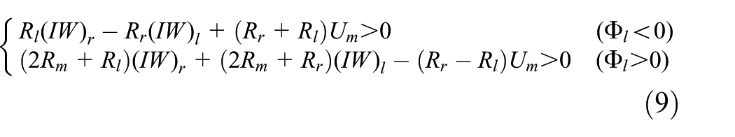
Combining equations (6), (7), and (9), we can deduce the following condition: if the direction of

Particularly, when the movable component is located at the position shown in Figure 2, there is the magnetic reluctance

Movement from right to left
Similarly, when the movable component is located at the rightmost position and a reverse current is applied, the attraction force is leftward. Then, the movable component moves leftward and stops at the leftmost position even after the removal of the electric current.
According to the qualitative analysis using the equivalent magnetic circuit method, we can see that this kind of hybrid electromagnet is feasible to move back and forth when the constraint conditions of the magnetomotive force between permanent magnet and coil windings are satisfied.
Electromagnetic force calculations by FEM
Based on the above theoretical analysis, an aircraft brake with a hybrid electromagnet has been developed. To analyze the operating characteristics and to obtain the precise electromagnetic attraction force, we take this brake as an example. The following calculations by FEM are conducted to obtain the distribution of the magnetic flux line, the magnetic flux density, and the attraction force versus position.
Main parameters of the hybrid electromagnet
The structural parameters of the hybrid electromagnet are shown in Table 1. The core and yokes are made of ferromagnetic material of Fe–Co alloy, which has a large saturation flux density and high Curie temperature. Figure 4 shows its B–H curve. 17 The rare-earth magnet is used to achieve a huge stationary attraction force because it can produce a significantly stronger magnetic field than other materials such as ferrite or alnico magnets. Its characteristic parameters include high working temperature of 120°C, great remanence of 1.4 T, and strong coercivity of 1700 kA/m.
Structural parameters of the aircraft brake.

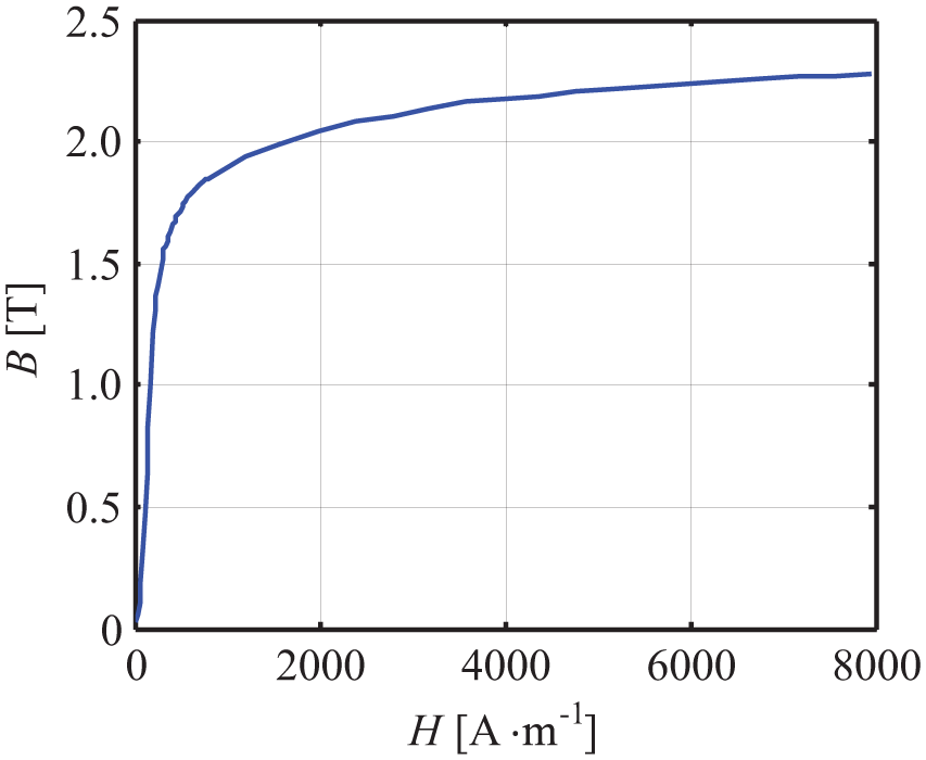
B–H curve of soft magnetic material of Fe–Co alloy.
Calculations of electromagnetic force
Due to the axially symmetrical structure of the hybrid electromagnet, only half section along the centric axis is analyzed. The FEM model includes a cup-shaped stationary component, a movable component, and air gaps. The hybrid electromagnet used in the aircraft brake is supplied by DC secondary power system. The rated voltage of the bus bar is 28 V, which is applied to the coil windings. In the case of the undervoltage 25.2 V (i.e. 10% fluctuation range of the rated voltage), electromagnetic force should also operate on the movable component. The following results are under the rated voltage across the windings. Additionally, results are similar when voltages are applied on the redundant coil windings.
Analysis when there is no current in the coil windings
The distributions of the magnetic line of force when there is no current in the windings are shown in Figure 5. Figure 5(a) and (b) represents the movable component located at two end positions, respectively. We can see from Figure 5(a) that the magnetic lines of force in the left stationary component and the movable component are much greater than those on the right side because of its large air gap. The simulation results validate the analysis based on the magnetic circuit method. The result is similar to Figure 5(b).

Distributions of magnetic line of force: (a) at the leftmost position and (b) at the rightmost position.
The distributions of magnetic flux density at both end positions are shown in Figure 6. We can see that when the magnet is the only magnetic source and the movable component parks at one of the sides, the magnetic flux density concentrates in the magnetic circuit on the parking side and that is very less in the other magnetic circuit. For example, when the movable component is located at the left side, as shown in Figure 6(a), the magnetic flux density in the left stationary component and the movable component is much higher than that in the right side.
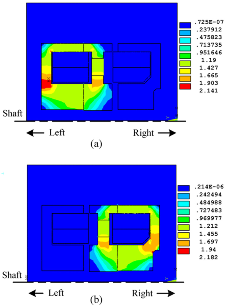
Distributions of magnetic flux density (T): (a) the movable component at the leftmost position and (b) the movable component at the rightmost position.
Analysis when current flows through the coil windings
Suppose that the movable component moves from left to right (the direction is determined by the designed electromagnetic attraction force). When DC forward current is flowing through the coil windings, the movable component tends to move rightward. Figure 7 shows the distributions of magnetic field lines and magnetic flux density when it is located at two end positions (Figure 7(a) and (c)) and at the middle position (Figure 7(b)).

Distributions of magnetic field lines (left) and magnetic flux density (right) (T) when the movable component is located at (a) the leftmost position, (b) the middle position, and (c) the rightmost position.
Figure 7(a) shows that when the movable component is located at the leftmost, the magnet flux in the right working gap becomes very large after the forward current is applied to the coil windings, which is the sum of that produced by permanent magnet and coils. In contrast, that in the left working gap becomes weak, which is the difference between that generated from permanent magnet and coils. Therefore, due to suffering a resultant force toward right, the movable component will move rightward. Figure 7(b) and (c) shows that the resultant force on the movable component is becoming larger as the movable component moves from left to right.
The attraction force exerted on the movable component is calculated by FEM when the movable part moves from one end position to another one. The calculation results of attraction force versus location are shown in Figure 8, where x-axis represents the air gap distance between the movable component and the leftmost position. When x equals zero, the resultant attraction force is 290 N rightward. The mathematical expression of attraction force versus location is fitted using a fifth polynomial as follows

where R2 is 0.99, showing the high fitting precision. The magnitude of resultant attraction force satisfies the load requirements of the electromagnetic brake.

Attraction force versus location.
Conclusion
A novel hybrid electromagnet with a permanent magnet has been proposed in this article, which can realize the bidirectional movement, energy saving, and high reliability. The constraint conditions of the magnetomotive force to realize the hybrid electromagnet are deduced by theoretical analysis. The FEM calculation results validate the theoretical analysis and the reasonable design. This electromagnet is designed for an electrical brake in MEA, but its structure can also be used in other applications such as aircraft or other industry, where critical reliability, bidirectional movement, and high retention force are essential.
Footnotes
Academic Editor: Yangmin Li
Declaration of conflicting interests
The author(s) declared no potential conflicts of interest with respect to the research, authorship, and/or publication of this article.
Funding
The author(s) received no financial support for the research, authorship, and/or publication of this article.