
Abstract
The horizontal directional drilling technology is widely used to lay the underground pipelines. These pipelines are of small or medium diameters with a dip angle ranging from 10° to 20°, special pipelines to 30°. In-pipe robot is commonly used to detect the pipeline fault. A new type of telescopic in-pipe robot is designed in this article, which is driven by step motor and screw, and supported by wheels. The robot has advantages of waterproof grade of IP68, stable motion state, and larger traction force. The speed is between telescopic robots and wheeled robots. Through force analysis and calculation, its maximum climbing angle is larger than 35°. The robot has good passing ability through the pipelines with bends. The inertial technology is used to locate the robot under the condition of disturbances. The pipeline fault detection algorithm based on the visual identification technology is designed to detect the pipeline fault. It can not only achieve autonomic positioning but also detect the pipeline fault.
Keywords
Introduction
The underground pipeline construction, especially the horizontal directional drilling (HDD) project, has been growing rapidly in recent years.1,2 In China, the HDD is widely used to lay the small- or medium-diameter underground pipelines with a dip angle ranging from 10° to 20°, special pipelines to 30°. 3 Generally, there is a large amount of sewage sludge inside the pipelines. And there are large weld beads in the iron pipeline. As an important part of the urban infrastructure, the underground pipelines undertake important functions such as power transmission, water supply, and communication. It is known as the lifeline of the city. 4 However, lack of detailed pipeline information and over-developing cause some issues, 5 such as pipeline leak and road surface collapse. 6 Thus, it is necessary to survey and maintain the underground pipeline in order to ensure the normal operation of the urban utility function.
At present, the positioning and detection of the underground pipeline mainly depend on manual detection. With the expanding scale of the underground pipeline, a new method should be developed, which is highly automated and advanced to meet the positioning and detection needs of the underground pipelines laid by the HDD.
In-pipe robot, belonging to the special robot field, is a kind of mechanical and electrical integration system to complete the pipeline operation. Typical in-pipe robots are divided into Smart PIGs, wheeled robots, tracked robots, and telescopic robots according to different driving mechanisms. 7 Comparison of typical in-pipe robot is shown in Table 1. Each type has some merits over others in certain aspects. The actual design adopted may depend on the task space of the required applications. We should keep in mind that in-pipe robots must be as simple and reliable as possible if they are to be used for the underground pipelines laid by the HDD (Table 2).
Comparison of typical in-pipe robot.

Definition of the pipe diameter. 2

Smart PIGs have been a typical example for passive locomotion robots. Passive devices, despite of their simple and economical structure, can make some trouble in the control. 8 The wheel robots can be divided into simple structure wheel robot and wall-pressed-type wheel robot. 9 Inspired from ground moving vehicles, early developers directly applied the four-wheel construction, such as IBAK robot, KA-TE robot, and OPTIMESS robot. They have simple structure and better velocity control. However, the traction depends on the frictional force between the wheel and the pipeline, which is correlated with the mass of the robot. In order to adapt to the particular in-pipe environment, many of the modifications have been tried. One is to add weight and equip the robot with more wheels for climbing, taking MAKRO 10 and Piko11,12 for example. As the number of wheels increases, the degrees of freedom and the complexity of control strategies also increase. Another one is to equip the robot with magnetic wheels so that it can adhere to the iron-made pipelines.13,14 However, the robot only applies to the iron-made pipelines. To strengthen the climbing ability, the wall-pressed-type wheel robot is developed. The wheels are mounted on the elastic arms which provide adaptability and required frictional force to the robot, such as MRINSPECT robot, 17 PipeTron robot, 15 and Explorer robot. 16 But these robots have several defects such as complex control strategies and large intersecting surface. Similar to the wheel robot, the tracked robot has large intersecting surface and large weight. Obviously, Smart PIGs, wheeled robots, and tracked robots have difficulties in adapting to such complex environments. Aiming at the characteristics of the underground pipeline laid by the HDD, a new type of telescopic in-pipe robot is presented in this article. It employs the motor-screw-driven structure with supporting wheel mechanism (SWM) to provide large traction force under a stable motion state. The architecture of the robot is simple and symmetric. It has small intersecting surface and can be used for the pipeline whose diameter is more than 70 mm. As a stable and reliable work platform, it is suitable for positioning and detection of the underground pipeline.
The core of the pipeline survey is usually positioning of the underground pipeline, which gets the three-dimensional (3D) coordinates to draw the pipeline laying track. In the current research, many kinds of positioning methods have been studied.18–20 However, it is difficult to apply the positioning methods to robots in such special working environment. The limitations of different methods are as follows: the positioning error determined by the odometer wheel accumulates greatly, 21 the static magnetic field method is easily disturbed by the magnetic field and the pipeline parameters, 22 the accuracy of the low-frequency electromagnetic pulse is also influenced by the pipeline parameters, 23 and the curvature sensor positioning is not suitable for straight pipeline. Scan matching is the process of matching two range scans obtained from a range device such as a camera, which has been applied to robot’s position in indoor and outdoor environments.24–26 It is difficult to ensure the accuracy of the scan matching for the long, straight pipelines with no feature. And the accuracy of the scan matching is influenced by the effects of lighting. With the development of the inertial technology, it becomes anti-disturbance and autonomic.27–29 First, it uses accelerometers and gyroscopes which are fixed on the robot to measure accelerations and angular velocities, respectively. Second, the attitude angle of the robot can be determined by the attitude calculation method. Then, the odometer is used to measure the mileage information of the system. Finally, the robot’s movement information is calculated only using attitude angles and the mileage information by the 3D dead reckoning. It can overcome the disadvantages of traditional positioning methods under the condition of disturbances, variable pipeline depths, and no features.
The underground pipeline maintenance is to carry out non-destructive testing of the pipeline that aimed to find out whether there is a crack or collapse. The CCTV (closed-circuit television) monitoring system installed on the robot is a kind of important means for the pipeline non-destructive detection, such as the PipeTron robot, Explorer robot, and Inuktun.16,30 It uses the length of the cable to locate the robot and identifies the pipeline fault depending on the operators’ experiences. It lacks pipeline fault autonomic identification function. With the rapid development of visual identification technology, it becomes possible to identify and classify the pipeline fault automatically. The fast median filter algorithm and image edge detection are designed to enhance the quality of the image and highlight the profile of the fault area. Then, the feature information is extracted from the image according to the distribution characteristics of the typical pipeline fault area. Finally, the improved K-mean clustering method is used to classify the pipeline fault.
Aiming at the characteristics of the underground pipeline laid by the HDD, a new type of telescopic in-pipe robot is presented in this article. It employs the motor-screw-driven structure with SWM to provide large traction force under a stable motion state. The inertial technology is applied to survey the pipeline to get the 3D information of the pipeline laying track. The positioning method includes the attitude angles’ measurement, attitude calculation method, and 3D dead reckoning. The 3D information can be measured, which is immune to disturbances and compatible with pipes of all materials. The pipeline fault detection algorithm based on the visual identification technology is designed to carry out non-destructive testing of the pipeline. The algorithm can be divided into three stages: image preprocessing, the fault feature extraction, and the fault classification. It can identify and classify the pipeline fault automatically. The robot in this article can meet the positioning and detection needs of the underground pipelines laid by the HDD.
System structure
The in-pipe robot developed in this article is used to measure the location of small- or medium-diameter pipelines laid by the HDD autonomously. While 3D location of its walking path is recorded continuously, the pipeline fault is detected in unknown complex environment. Therefore, the robot functions should be defined as follows:
The robot can walk up to 200 m inside the pipeline under the control of the monitor computer.
The robot can adapt to the pipelines with different materials and diameters.
The robot may provide stable motion state and large traction force. Its maximum climbing angle is 35°. The robot has the capability to take extra load and provide extra power to extend to other modules, such as carrying ultrasonic flaw detector.
The waterproof sealing performance is IP68 for the pipelines with large quantities of sewage sludge.
The robot may measure 3D locations of its walking path precisely under the condition of disturbances and variable pipeline depths. Therefore, the position of the pipeline can be measured by the robot.
The CCTV monitoring sub-system is required by the robot to transmit the video signal collected in the pipeline to the monitor computer in real time. The pipeline fault detection algorithm based on the visual identification technology is required to assist the operator to identify the pipeline fault.
Mechanical structure
The mechanical structure of the robot system consists of SWM, locking mechanism (LM), telescopic mechanism (TM), and main body (MB), as shown in Figure 1(a). The function of each mechanism is as follows:
MB. The control module and positioning module of the robot are installed inside the MB to avoid external damage. The MB also has good waterproof sealing performance.
TM. The basic telescopic action is executed to realize robot’s walking.
LM. There is same structure between locking mechanism A (LMA) and locking mechanism B (LMB). LM is locked when crutch legs keep locking with the pipe wall.
SWM. There is same structure between supporting wheel mechanism A (SWMA) and supporting wheel mechanism B (SWMB). When LM is unlocked, the SWM supports the robot.

Mechanical structure of the system: (a) model and (b) prototype.
As shown in Figure 1(b), the overall length of complete robot is 1.7 m. There are four segments connected by flexible hinges. It has small intersecting surface and can be used for the pipeline whose diameter is more than 70 mm.
The TM consists of a step motor, shaft coupling, bearing, ball nut, nut seat, linear bearing, scalable putt, guide rail, ball screw, position limit device, and connecting seat as shown in Figure 2. The step motor is installed in the motor chamber, and the output shaft of the motor is connected with the fixed side of the ball screw through a shaft coupling. The rotary motion of the motor shaft is converted into the axial movement of the ball nut, and the nut seat is driven to execute the extension and contraction of the TM. The TM is equipped with two guide rails which are used to limit the rotation of the ball nut and increase the strength of the system. The nut seat is fixed with a ball linear bearing, and the friction between the guide rail and the nut seat is reduced.
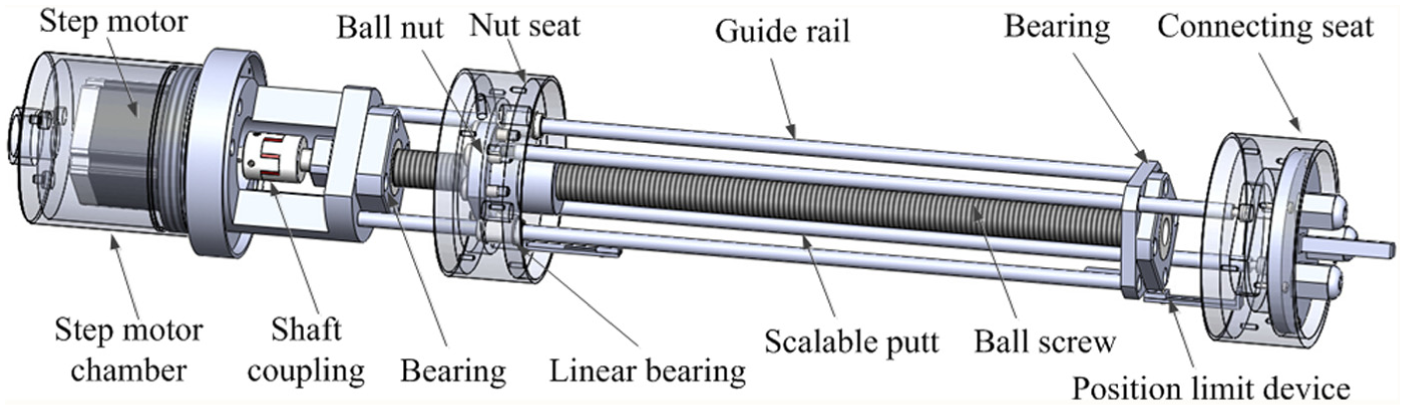
Telescopic mechanism (TM).
The LM (shown in Figure 3) is a motor-screw-driven structure, which is similar to the TM. The step motor is installed in the motor chamber, and the output shaft of the motor is connected with the ball screw through a shaft coupling. The rotary motion of the motor shaft is converted into the axial movement of the ball nut, and the supported area is pressed strongly against the pipe walls by the crutch legs to realize reliable locking of LM.

Locking mechanism (LM).
The SWM has three wheels fixed circumferentially 120° apart from each other. One end of the crutch leg is connected to the installation base, and the other end is connected to the movable support. The center of the movable support is equipped with a linear bearing. A spring is arranged between the movable support and the fixed base. Under the action of the spring, the supporting wheel can be pressed against the pipe walls (Figure 4).

Supporting wheel mechanism (SWM).
Hardware design
The hardware design of the robot system consists of three parts (Figure 5): motherboard of the in-pipe robot, sensor system, and monitor computer. The hardware circuit of the in-pipe robot can be divided into power supply module, Digital Signal Processor (DSP) + Complex Programmable Logic Device (CPLD) module, motor drive module, communication module, navigation module, and video transmission module. The functions of each module are as follows:
Power supply module. It supplies the operating voltage to other modules of the in-pipe robot system.
DSP + CPLD module. It is the core of the control circuit, which is responsible for the control and conversion of walking state, data acquisition and processing, and so on.
Motor drive module. It receives the control signal from DSP + CPLD module and generates the control pulse sequences of the step motor.
Communication module. DC-carrier technology is employed to realize the real-time two-way communication between the robot and the monitor computer, and a RS232 interface is integrated for system expansion.
Navigation module. Navigation module is mainly composed of gyroscopes and accelerometers which are fixed on the robot to measure angular velocities and accelerations, respectively. Combined with the mileage information obtained by the odometer, the robot’s movement information is calculated in the DSP + CPLD module.
Video transmission module. It is responsible for uploading videos, captured by the CCD (charge-coupled device) camera, to the monitor computer.
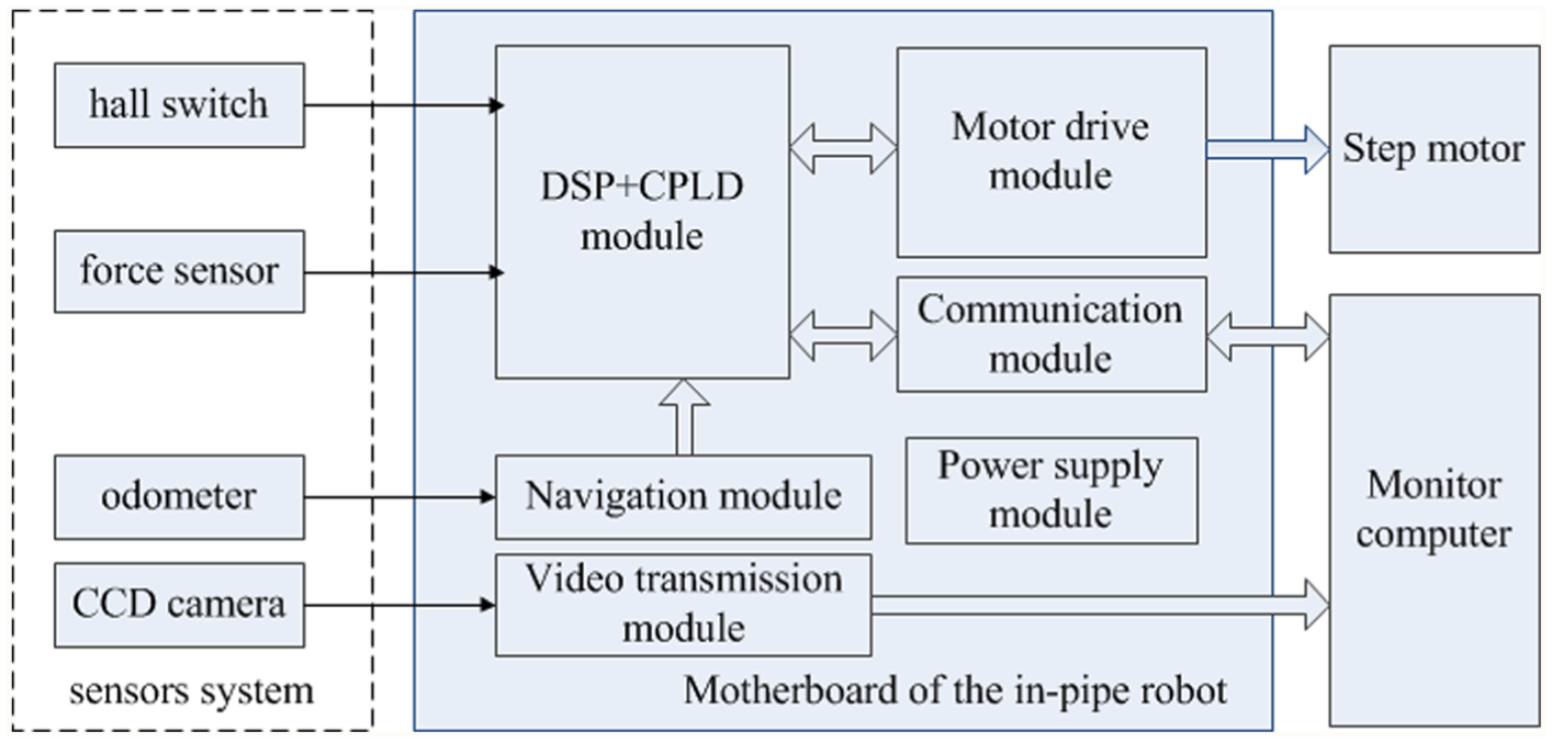
Hardware design of the system.
Software design
This section describes the special software developed for the monitor computer which is designed according to the framework of the robot control system. This software includes five modules as shown in Figure 6:
Control/communication module. It controls the robot remotely and communicates with it in real time. It sends control messages to the robot and receives the robot state information.
Video capture module. It receives analog video signal captured by the CCD camera.
Calculation module. It expresses the 3D trajectory of the robot in OpenGL coordinate system. The pipeline fault detection algorithm based on the visual identification technology assists the operator to identify the pipeline fault according to the video information.
Display module. It contains the 3D trajectory display module and the video display module. The 3D trajectory display module expresses the robot walking path (pipeline) in both 3D and 2D graphics. The video display module shows the underground pipeline inside video in real time. The software interface is shown in Figure 7(a) and (b). It can achieve a panoramic description of the underground pipeline.
Data management module. It saves the 3D trajectory information and videos of the underground pipeline in special format. It is helpful to further research.

Software design of the system.

Software interface: (a) 3D trajectory display interface and (b) video display interface.
Analysis of the in-pipe robot performance
The mechanical model is set up and the force analysis is presented, which includes the cable’s towing resistance (
Force analysis of the in-pipe robot
In order to analyze the force conveniently, the definitions of some parameters and their descriptions are shown in Table 3.
Definitions and descriptions.
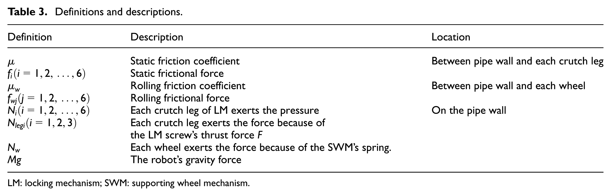
LM: locking mechanism; SWM: supporting wheel mechanism.
As shown in Figure 8(a), the robot stays in a pipeline with a dip angle
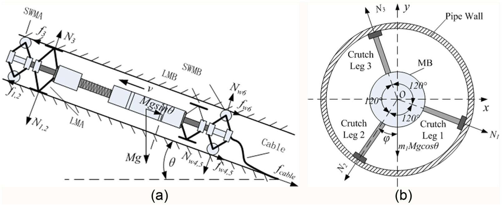
Force analysis: (a) robot stays in an inclined pipeline and (b) LMA status of the robot.
Cable’s towing resistance
This robot is mainly used for the pipeline laid by the HDD. These pipelines typically consist of three parts (shown in Figure 9): horizontal pipeline (

Underground pipelines.
Generally,
Calculation parameters.
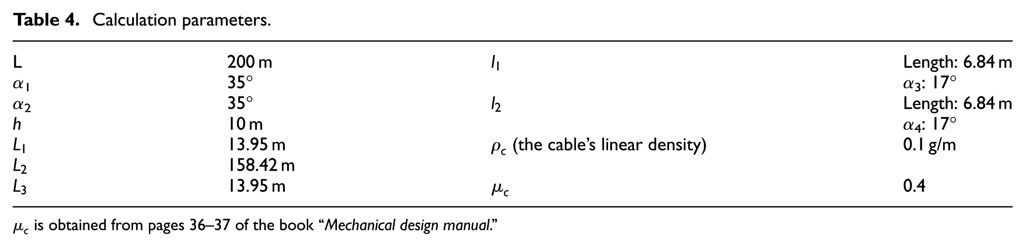
The cable’s towing resistance 31 is

Using equation (1),

To have adequate safety allowance,
Locking condition analysis of LM
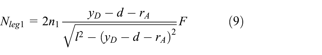
Reliable locking of LM is a precondition for the robot’s walking. As shown in Figure 8(a) and (b), to ensure reliable locking of LMA,

where
As long as the materials of the robot are determined,

where
Similarly,

Each LM has three crutch legs fixed circumferentially 120° apart from each other. Due to circumferential symmetry of LM’s crutch legs, it is considered that screw’s thrust force exerted on each crutch leg is


Mechanical model of the LM’s crutch leg.
The differential equation of equation (5) is

Based on the principle of virtual displacement, there is

Choosing

Equations (6)–(8) lead to
Similarly,

According to the above equations,

The locking condition of LMA is written as

Above results indicate that the locking condition of LMA is not correlated with the screw’s thrust force exerted on each crutch leg
Screw’s load forces of TM
TM executes the contracting action when LMA is locked and LMB is unlocked (shown in Figure 8(a)). The axial load force of the screw of the TM (

When LMA is unlocked and LMB is locked, the axial load force of the screw of the TM (

Calculation of climbing and load capacity
The parameters of the screw’s load force of TM (
Parameters of the screw’s load forces of TM.

Combining equations (10) and (11) with Table 5,


Ignoring the friction between the screw and the guide rail, the equivalent load of the screw is
Then, the rating dynamic load of the screw
32
is
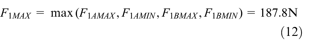
The ball screw FSI20-5T3 is used for the screw of the TM, and its rating dynamic load 11.4 kN is far greater than
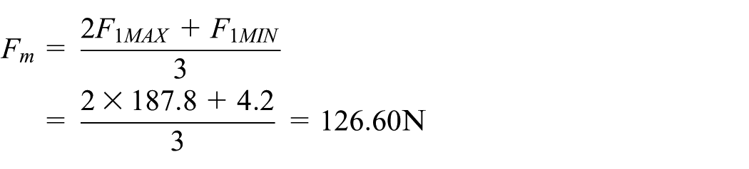
According to the force analysis and equation (12), the maximum load of the motor of the TM is

where
The friction torque produced by
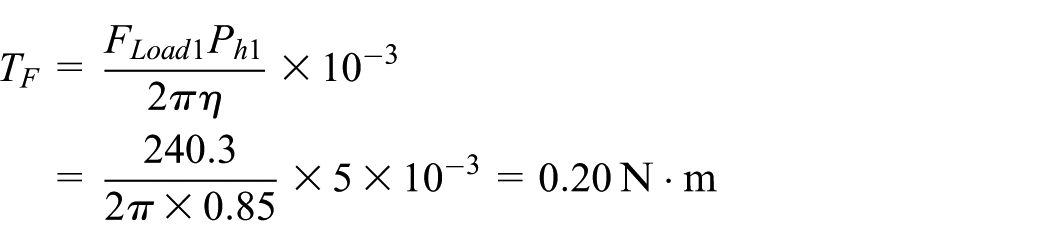
where η and
The FSI20-5T3 chooses no pre-tightening structure, so the pre-tightening torque is presented as

When the speed of the motor increases from 0 to the maximum speed, the maximum acceleration torque can be written as

where J is the total moment of inertia of the motor,
The maximum starting torque

The relation between the static torque and the maximum starting torque of the step motor is as follows
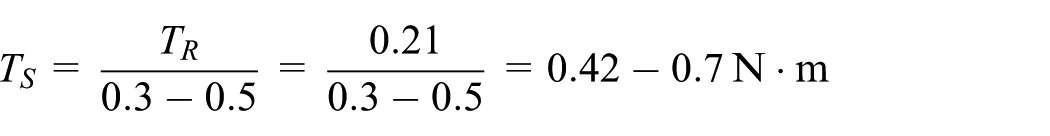
The two-phase hybrid step motor SS2304A42A is adopted by TM, and its static torque is 2.4 N·m which is far greater than
Waterproof ability
In order to ensure the reliable operation of the robot in the complex environment, the protection level of IP68 is adopted for a good waterproof performance. It can prevent dust from entering into the MB completely, and it enables the robot immersing under water of 10 m depth for 24 h without affecting its normal work. As shown in Figure 1(b), the material of the SWM adopts 304 stainless steels for corrosion resistance and the LM, TM, and MB are made by aviation aluminum.
Several waterproof measures of the TM (shown in Figure 11) are taken as follows:
The main interface uses the 55° sealing pipe thread and the O-type rubber sealing ring.
A retractable waterproof screw sheath is added to the lead screw that is connected to the MB with the flange.
The cable connection of the TM is waterproof.
The important interface is protected by the waterproof sealant.
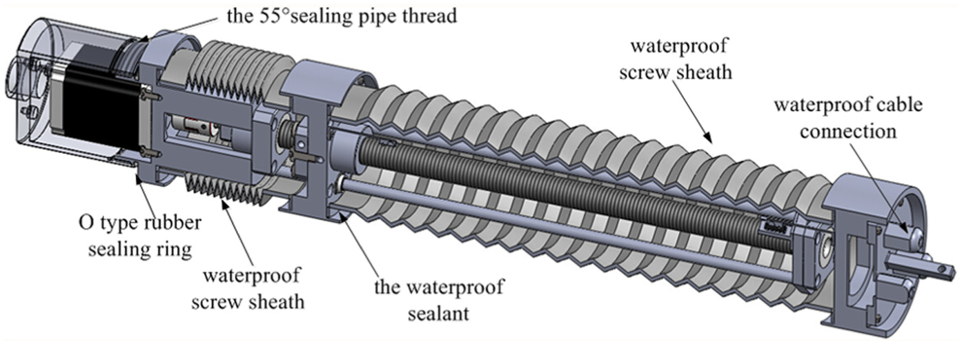
Waterproof design of the TM.
The waterproof design of the LM is same as that of the TM because of the similar structure. The MB must have good waterproof sealing performance which installs the control module and positioning module of the robot to avoid external damage. In order to verify the waterproof performance of the MB, the water pressure test should be carried out. It is difficult to observe the waterproof condition of the MB under the water, so a waterproof experimental device is designed. And it is easy to observe the waterproof condition outside the MB through the waterproof experimental device. It includes the MB, waterproof cable connection, catheter, pressure gauge, and valve (shown in Figure 12). In order to simulate that the MB is under the water, there is certain pressure inside the MB which is equivalent to the underwater environment.
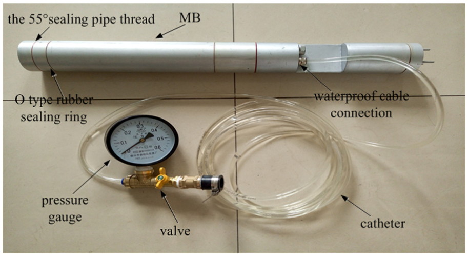
Waterproof experimental device.
When the robot works under the water, the pressure P of the MB is equal to the water pressure
In order to simulate that the MB is under the water, the pressure
Water pressure test.


Water pressure test.
Passing ability analysis of the robot through the pipelines with bends
As shown in Figure 1(b), the overall length of complete robot is 1.7 m. There are four segments connected by flexible hinges. The longest segment is the MB with a length of 530 mm, while the shortest segment is the SWM with a length of 76 mm. So, the passing ability of the robot through the curve pipe depends on the longest segment.
As shown in Figure 14, if the robot can pass through the curve pipe, there is a geometric relation
That is

where R is the curvature radius of the curve pipe, D is the diameter of the pipeline, L is the length of the longest segment, and d is the circumcircle diameter.

Passing ability analysis of the robot.
The designed robot is applicable to the pipelines with a diameter of more than 70 mm. Choosing
Underground pipelines are divided into directly buried pipelines and trenchless pipelines. The directly buried pipelines can be approximately regarded as straight pipeline. As shown in Figure 9, the curvature radius of the trenchless pipelines is larger than 400D. It is clear that the curvature radius of the underground pipelines has no effect on the robot.
Control method
Autonomous walking of the in-pipe robot
The walking of the telescopic in-pipe robot in the pipeline has the characteristic of intermittent type, and the long-distance walking consists of many basic telescopic movements. In order to describe the walking principle conveniently, the movement principles of the TM and LM are introduced as follows.
The extension and contraction of the TM: the TM (shown in Figure 2) is a motor-screw-driven structure. The step motor is installed in the motor chamber, and the output shaft of the motor is connected to the fixed side of the ball screw through a shaft coupling. The rotary motion of the motor shaft is converted into the axial movement of the ball nut, and the nut seat is driven to execute the extension and contraction of the TM. When the motor of the TM rotates in the positive direction, the TM executes the extension. On the contrary, when the motor rotates in the negative direction, the TM executes the contraction.
The reliable locking of the LM: the LM (shown in Figure 3) is a motor-screw-driven structure, which is similar to the TM. The step motor is installed in the motor chamber, and the output shaft of the motor is connected to the ball screw through a shaft coupling. The rotary motion of the motor shaft is converted into the axial movement of the ball nut. When the motor of the LM rotates in the positive direction, the supported area is pressed strongly against the pipe walls by the crutch legs to realize reliable locking of the LM. On the contrary, when the motor rotates in the negative direction, the supported area moves away from the pipe walls and the LM is unlocked.
As shown in Figure 15(a)–(d), the robot walks along the pipe to the left, and a basic telescopic movement is composed of the following states:
State A. Two LMs are locked to prevent the robot from moving freely.
State B. When the LMA is unlocked and the LMB is locked, the TM executes the extension and the robot’s front end moves to the left driven by the TM.
State C. When the LMA is locked and the LMB is unlocked, the TM executes the contraction and the robot’s back end moves to the left ΔL driven by the TM.
State D. The robot repeatedly executes state B and state C to achieve long-distance walking.

Walking principle: (a) state A, (b) state B, (c) state C, and (d) state D.
If the robot wants to walk along the pipe to the right, the robot should first execute state A; second, execute state C; third, execute state B; and finally, repeatedly execute state C and state B to achieve long-distance walking. There is a human intervention by the operator in special case such as “Y”-type branching in the pipeline. The operator makes a decision about how the robot passes the “Y”-type pipeline, then the monitor computer sends control messages to the robot, and finally, the robot passes the “Y”-type branching in the pipeline with human intervention.
The walking patterns of the telescopic in-pipe robot can be divided into continuous forward walking (CFW), continuous backward walking (CBW), single step forward walking (SSFW), and single step backward walking (SSBW). With the help of the SWM, the robot’s walking path is fixed in the pipeline, so the control of the robot’s walking patterns focuses on the coordination control of the robot’s mechanisms. In order to limit the power consumption in motor, there is only one motor at work at the same time. Based on the above analysis, the control of the robot’s walking patterns can be attributed to the working state conversions among the motor of the TM, the motor of the LMA, and the motor of the LMB.
Finite-state machine theory is good at describing finite state and its transformation. It is widely used in digital circuit design, software design, and robot control. Therefore, the input and output events of the four basic walking patterns are abstracted based on the finite-state machine theory and the state sets of the different walking patterns are designed.
The input and output signals of the state machine
The input signal of each walking pattern is as follows:
Limiting displacement signal (P). It prevents the TM and the LMs out of the safe journey of the screw.
The pressure signal of the LM (N). It detects the pressure
Stop signal (S). It expresses whether the robot received the stop instruction from the monitor computer or not.
Single step signal (T). It expresses whether the robot received the single step instruction from the monitor computer or not.
The values of the input signals and their definitions are shown in Table 7.
Definition of input signals.

The output signal of each walking pattern consists of a four-bit binary number (M = M4M3M2M1), which is, respectively, the direction of rotation and the enabling signal of three motors. The values of the output signals and their definition are shown in Table 8, for example, M = 1010 expresses that motor of the LMA reverses.
Definition of output signals.

State machine description of basic walking patterns
The walking patterns of the telescopic in-pipe robot can be divided into CFW, CBW, SSFW, and SSBW. On the basis of the walking principle of the robot, the control of the robot’s walking patterns can be attributed to the working state conversions among the motor of the TM, the motor of the LMA, and the motor of the LMB. Thus, the control logic of autonomous walking of the in-pipe robot is that how to convert the working state among three motors. Finite-state machine theory is good at describing finite state and its transformation. So, we use the finite-state machine to describe the robot walking patterns in order to get the state transition diagram.
The mathematical model of the state machine can be described as follows

where Q is the finite set of the state and it is not empty,
According to the walking principle of the robot, the robot repeatedly executes the basic telescopic action until the monitor computer sends the stop instruction, so the state machine models of CFW and CBW are as follows

where
When the robot receives the CFW instruction, the robot begins the CFW pattern. The state transition diagram of CFW is shown in Figure 16.
State transition diagram of CFW.
Similar to the CFW mode, the state transition diagrams of CBW, SSFW, and SSBW are obtained respectively. Single step walking pattern of the in-pipe robot can make operators carry out non-destructive testing of the pipeline step by step.
Conversion of walking patterns
The operators can change the walking patterns of the robot through the monitor computer. And the state machine model of the walking pattern conversion is as follows

where A0 is the initial state, A1 is the CFW, A2 is the CBW, A3 is the SSFW, A4 is the SSBW, A5 is the state of termination, and C is the control signal.
The values of the control signals and their definitions are shown in Table 9.
Definition of control signals.

Based on the above analysis, the state transition diagram of the conversion of walking patterns is shown in Figure 17.

State transition diagram of the conversion of walking patterns.
3D information measurement method
Dead reckoning algorithm is used to calculate 3D information. Accelerometers and gyroscopes are fixed on the robot to measure accelerations and angular velocities, respectively. Combined with the mileage information, 3D location of the robot’s walking path is calculated by the dead reckoning algorithm.
Attitude calculation method
The geographic coordinate system (east-north-up) is chosen for the navigation coordinate system (

where
So, the transformation matrix is

The direction cosine matrix
According to equations (14) and (15), the principal value of the three attitude angles can be derived as

The true value of the three attitude angles can be determined by the principal value,
The attitude matrix elements can be used to solve the attitude angle of


where
Therefore, as long as the initial attitude angle is given, the differential equation can be determined by the attitude angle rate
3D dead reckoning
The 3D dead reckoning is the way that calculates the trace only using attitude angles and the mileage information of the system. Its principle is to divide the trajectory into a number of segments, each of which is determined by the length of the system’s movement within a sampling period (shown in Figure 18).

Vector’s projection.
The projection can be written as

where
Attitude angles’ measurement
The attitude angles’ measurement method uses gyroscopes for underground applications. Gyroscopes are immune to ferromagnetic and electromagnetic disturbances, but they have considerable DC drifts in a relatively long period of time. The accelerometer has high precision when it is in the static state, but it has poor accuracy when it is in motion. So, a reliable and precise way to measure pitch angle and roll angle is using a 3-axes accelerometer when the robot is in static state. The pitch angle and roll angle are regarded as the initial value of the gyroscope. When the robot is in motion, the output of the gyroscope serves as the attitude angles.
According to the attitude matrix

where
The pitch angle and roll angle can be expressed as follows

The three axes of the accelerometer are mutually perpendicular. When one axis is at its minimum sensitivity of gravitational acceleration, the other two axes combined will be at the maximum sensitivity. A sensitivity of approximately 17.45 mg/degree at any tilt orientation could be maintained for pitch and roll angles. 33 Most of the low-cost MEMS (micro-electro mechanical system) accelerometers can provide 0.1–1 mg resolution. This is accurate enough for the pitch and roll angles.
To improve the measuring precision of the attitude angles, the static calibration system of the accelerometer is established, and the error compensation of the accelerometer is calculated. The extended Kalman filter (EKF) is designed to filter out the
The nonlinear system equations are given as follows

where the noise processes
The EKF can be summarized as the time-update equations and the measurement-update equations. The procedure of this algorithm is as follows:
1. The time-update equations for
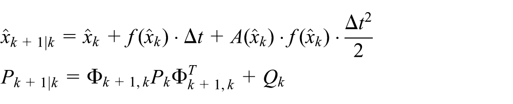
where
2. The measurement-update equations for K,
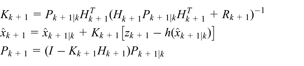
where K is the Kalman filter gain and
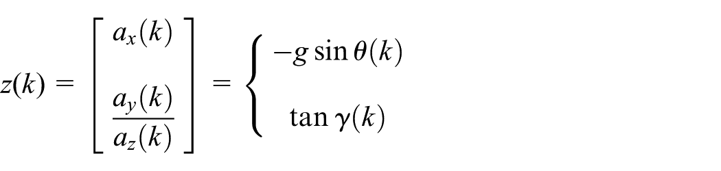
The pitch angle and roll angle are chosen as the state of the system, and
So the discrete-time equations of the system are as follows

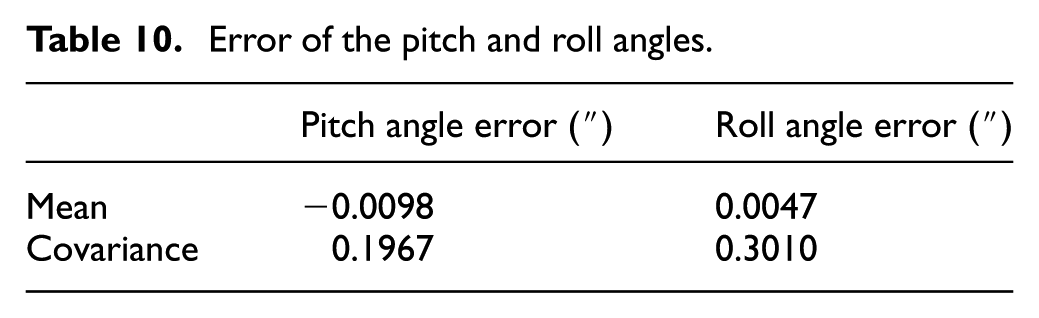
Assuming that the accelerometer can provide 1-mg resolution, the result of EKF simulation is shown in Figure 19. According to Table 10, the pitch angle error is less than 2″ and the roll angle error is less than 3″. It is accurate enough for the attitude angles’ measurement of static state.

Result of EKF simulation.
Error of the pitch and roll angles.
Finally, the robot’s movement information is calculated by the 3D dead reckoning. The robot’s movement information consists of many relative coordinates. The starting point and the ending point of the pipeline (measured by the whole station instrument or global positioning system (GPS)) are used to improve the accuracy of the robot’s inertial positioning. We develop the conversion from the relative coordinate system to the geographic coordinate system using the starting point and the ending point of the pipeline.
Pipeline fault detection of the in-pipe robot
The CCTV monitoring sub-system is used for the pipeline detection remotely. The telescopic in-pipe robot takes the CCD camera to shoot the video of the pipeline’s interior and transmits it to the monitoring computer through the twisted-pair cable in real time. The transmission principle is shown in Figure 20.

Video transmission principle diagram.
The pipeline fault detection algorithm based on the visual identification technology is designed to assist the operator to identify the pipeline fault. In order to identify the fault type of the pipeline, the feature information is extracted from the video information of the CCD camera.
Image preprocessing is used to eliminate the influence of noise and distortion caused by the process of the image generation and transmission. The noise of the CCD sensor is the discrete random noise in this article, so the median filter algorithm is chosen for image preprocessing.
The fault feature extraction is the core of the visual detection algorithm. For underground pipelines with small or medium diameter, the typical pipeline fault types are generally pipeline cracks, pipeline holes, and pipeline interface tear (shown in Figure 21). The fault area of each fault type has distinctive characteristics. The pipeline’s hole area is close to the circular, the crack area is the branch shaped, and the pipeline interface tear area is annular.
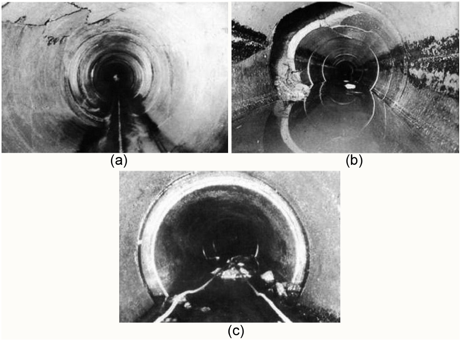
Fault types of a typical pipeline: (a) pipeline cracks, (b) pipeline holes, and (c) pipeline interface tear.
According to the characteristics of the fault area, the pipeline fault types are isolated according to different parameters of minimum enclosing rectangle. So, the feature vector
Selecting 199 clear pipeline failure image samples (pipeline cracks: 89, pipeline holes: 77, and pipeline interface tear: 33), the feature vector is shown in Figure 22. The distribution of the fault feature vector is different, and the distribution of the vulnerability is in the region. The feature vector of the pipeline hole is

Feature vector {l, s} of typical pipeline fault types.
With this feature, the fault classification uses the K-mean clustering method. The distance function of the K-mean clustering method is the Euclidean distance of the sample points to the class center point
According to the algorithm, 199 feature vectors are clustered (shown in Figure 23).

Clustering results based on K-mean clustering method.
In Figure 23, asterisk “*” represents the feature vector of the pipeline hole, circle “O” represents the feature vector of the pipeline crack fault, plus sign “+” represents the feature vector of the pipeline crack fault, red asterisk shows that the feature vector is clustered as the pipeline hole, blue circle shows that the feature vector is clustered as the pipeline crack, and black plus shows that the feature vector is clustered as the pipeline interface tear.
The simulation of pipeline fault detection algorithm based on the K-mean clustering method is carried out 1000 times in MATLAB. The samples are 199 clear pipeline failure image samples (pipeline cracks: 89, pipeline holes: 77, and pipeline interface tear: 33). As shown in Table 11, there are 11 types and each type has different incorrect times. The average correct rate of the K-mean clustering method is 85.52%.
Simulation results of the K-mean clustering method.
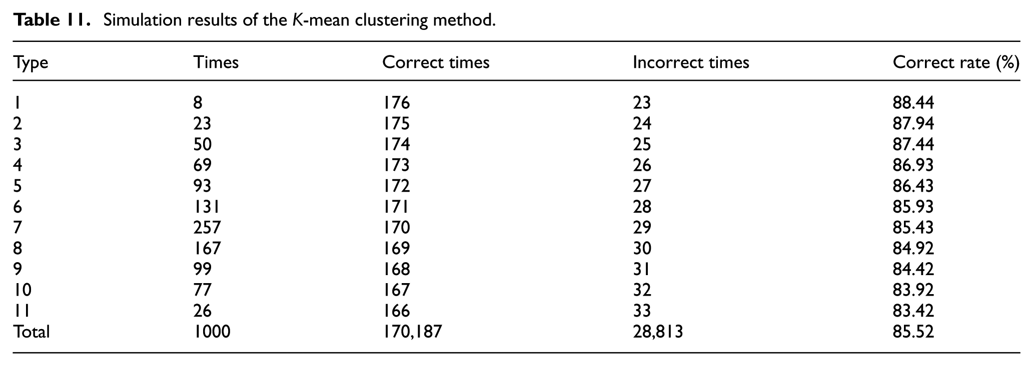
The reason for the above simulation results is that the feature vector of the pipeline hole is close to the feature vector of the pipeline crack. And the distribution of the feature vector of the crack is larger than the hole. With this feature, the feature vector

Feature vector of typical pipeline fault types.
In Figure 24, r is
The distance function of the improved K-mean clustering method is as follows

where X is equal to
According to the improved algorithm, 199 feature vectors are clustered (shown in Figure 25).

Clustering results based on improved K-mean clustering method.
In Figure 25, asterisk “*” represents the feature vector of the pipeline hole, circle “O” represents the feature vector of the pipeline crack fault, plus sign “+” represents the feature vector of the pipeline crack fault, red asterisk shows that the feature vector is clustered as the pipeline hole, blue circle shows that the feature vector is clustered as the pipeline crack, and black plus shows that the feature vector is clustered as the pipeline interface tear.
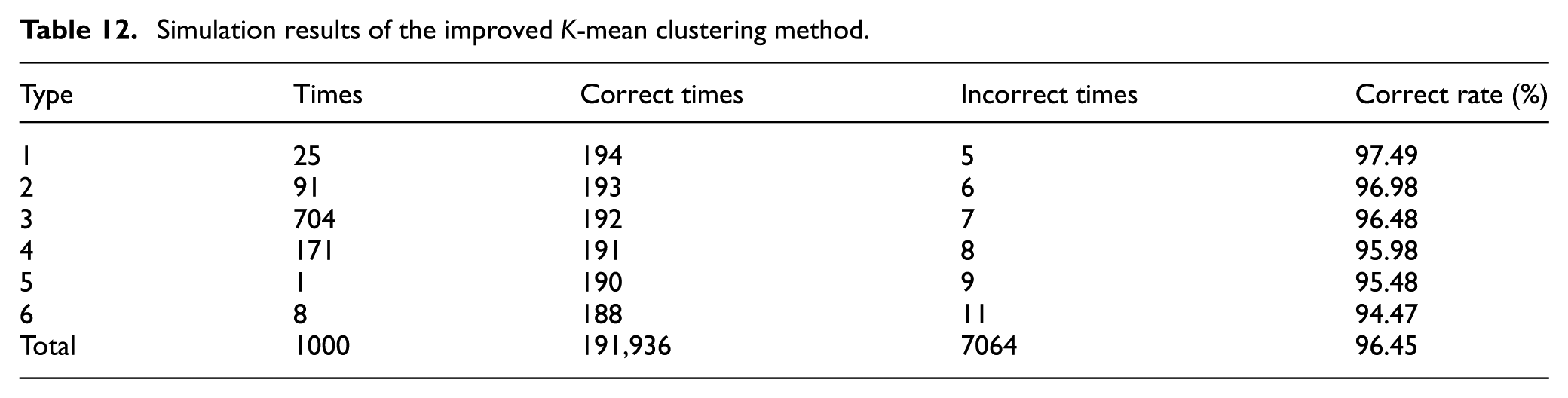
The simulation of pipeline fault detection algorithm based on the improved K-mean clustering method is carried out 1000 times in MATLAB. The samples are similar to Table 11. As shown in Table 12, the average correct rate of the improved K-mean clustering method is 96.45%. The average correct rate of the clustering results increased from 85.52% to 96.45%.
Simulation results of the improved K-mean clustering method.
A necessary precondition is that the CCTV module can capture the clear image of flaws so as to improve the pipeline fault detection performance. When the pipe is filled with a semi-transparent liquid, the CCTV module captures the unclear image of flaws. The unclear image of flaws will produce effects on the extracting for image features. As the core of the visual detection algorithm, the fault feature extraction directly affects the correct rate of the visual detection algorithm. When there is a doubt whether the pipeline has flaws in engineering, it is supposed to drain the semi-transparent liquid in the pipeline to detect the pipeline again.
Field tests
The field test is based on the test pipeline, including the positioning test, the climbing and load capacity, passing ability in the bent pipe, and the pipeline fault detection algorithm test. The test pipeline (shown in Figure 26) is designed according to the characteristics of the underground pipelines laid by the HDD. The test pipeline with the length of 97.56 m is laid on the ground in Changping, Beijing. It consists of three parts: horizontal pipeline, curve pipelines, and inclined straight pipelines. The diameter of the pipeline is 140 mm, and the curvature radius is more than 37D.

Test pipeline.
According to the characteristics of the underground pipelines laid by the HDD, the test pipeline can be seen on the ground (shown in Figure 27).
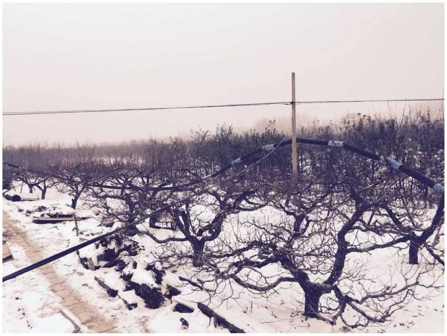
Test pipeline on the ground.
The robot achieves the positioning of the walking path through the pipeline. Figure 28, the robot’s walking path (shown in yellow), is compared with the test pipeline trace (shown in red) measured by the whole station instrument. The maximum errors of the vertical and horizontal directions are, respectively, less than 0.05 and 0.10 m. According to “code for surveying and mapping underground pipelines and cables,” 34 the maximum errors of the vertical and horizontal directions should be, respectively, less than 0.10h and 0.15h (h: depth of the pipeline). Apparently, the positioning accuracy meets the requirements of the Chinese industry.

Result of the robot’s inertial positioning.
The test pipeline trace has been measured by the whole station instrument. There are 975 measurement points. And the distance between each data point is 10 cm. When we verify the accuracy of the robot’s inertial positioning, the robot climbs this test pipeline with a 30-kg load. Therefore, we can verify the climbing and load capacity according to the test. The two adjacent measurement points among 975 points form a line segment. The slope angle of the pipeline can be calculated by the included angle between the line segment and the horizontal plane.
The line segment

According to the above equation, the slope angle of the test pipeline is calculated. The

Slope angle of the pipeline.
To confirm the performance of the pipeline fault detection algorithm, the robot detects the artificial faults in the PVC pipeline (including the pipeline cracks, pipeline holes, and pipeline interface tear), as shown in Figure 30. The robot detects 350 pipeline images (including 281 fault images), and the result of the feature extraction is shown in Figure 31.

Artificial fault in the PVC pipeline.

Result of the feature extraction.
The algorithm can correctly identify 225 fault images, and the fault recognition rate is as high as 80.07%. The algorithm can classify 190 pipeline faults, and the fault classification rate is 67.61%. Obviously, the pipeline fault detection algorithm based on the visual identification technology can assist the operator to identify and classify the pipeline fault.
Conclusion
Typical in-pipe robots have difficulties in detecting the small- or medium-diameter pipelines laid by the HDD with a dip angle ranging from 10° to 20°, special pipelines to 30°. Aiming at the characteristics of the underground pipeline laid by the HDD, a new type of telescopic in-pipe robot is designed in this article, which has prominent climbing and load capacity, autonomic positioning, and the pipeline fault autonomic identification function. The robot can meet the location and detection needs of the underground pipelines laid by the HDD.
The mechanical structure of the robot system consists of SWM, LM, TM, and MB. It has small intersecting surface and can be used for the pipeline whose diameter is more than 70 mm. The LM and TM are the motor-screw-driven structures. The output shaft of the motor is connected with the fixed side of the ball screw through a shaft coupling. The rotary motion of the motor shaft is converted into the axial movement of the ball nut, and the nut seat is driven to execute the extension and contraction.
The force analysis is presented, which includes the cable’s towing resistance, the locking condition analysis of the LM, and the screw’s load forces. Through force analysis and calculation, the maximum climbing angle of the robot is larger than 35°. With the traction force, the robot can be equipped with other modules to expand the function. In order to adapt to harsh environment, its waterproof grade is designed as IP68 that can work normally for a long time under water of 10 m depth. Based on the passing analysis of the in-pipe robot, it is clear that the curvature radius of the underground pipelines laid by the HDD has no effect on the robot.
On the basis of the walking principle of the robot, the control of the robot’s walking patterns can be attributed to the working state conversions among the motor of the TM, the motor of the LMA, and the motor of the LMB. Thus, the control logic of autonomous walking of the in-pipe robot is that how to convert the working state among three motors. The walking patterns of the telescopic in-pipe robot are divided into four patterns: CFW, CBW, SSFW, and SSBW. The four basic walking patterns and conversion of walking patterns are abstracted based on the finite-state machine theory. The state transition diagram describes the control logic of autonomous walking of the in-pipe robot.
The inertial technology is applied to survey the pipeline to get the 3D information of the pipeline laying track in this article. First, it uses accelerometers and gyroscopes which are fixed on the robot to measure accelerations and angular velocities, respectively. Second, the attitude angle of the robot can be determined by the attitude calculation method. Then, the odometer is used to measure the mileage information of the system. Finally, the robot’s movement information is calculated through attitude angles and the mileage information by the 3D dead reckoning. The 3D information can be accurately measured, which is immune to disturbances and compatible with pipes of all materials. Through a series of field tests, positioning accuracy meets the requirements of the Chinese industry.
The pipeline fault detection algorithm based on the visual identification technology is designed to identify and classify the pipeline fault automatically for inspection. The algorithm can be divided into three stages: image preprocessing, the fault feature extraction, and the fault classification. The fast median filter algorithm and image edge detection are designed to enhance the quality of the image and highlight the profile of the fault area. Then, the feature information is extracted from the image according to the distribution characteristics of the typical pipeline fault area. Finally, the improved K-mean clustering method is used to classify the pipeline fault. The fault recognition rate of the algorithm is as high as 80.07%, and the fault classification rate is 67.61%.
Footnotes
Academic Editor: Neal Y Lii
Declaration of conflicting interests
The author(s) declared no potential conflicts of interest with respect to the research, authorship, and/or publication of this article.
Funding
The author(s) received no financial support for the research, authorship, and/or publication of this article.