
Abstract
Air bearings have been widely used in ultra-precision positioning stages due to the property of nearly zero friction or wear. Small vibration of the bearing reduces the overall moving and positioning precision of the stage and hampers its applications in fabrication facilities requiring nanometer moving and positioning precision. In order to improve system precision, knowledge of the dynamic characteristics of air bearings is the first and crucial step. However, it is still a challenge to set up an accurate dynamic model for air bearings due to the system complexity. In this article, a novel method for the dynamic modeling of air bearing is proposed, which takes into account the dynamics in both the moving direction and the supporting direction. An ultra-precision positioning dual stage is investigated using the proposed dynamic modeling method. This stage has two sets of air bearings and can be used in integrated circuit fabrication equipments. Moreover, dynamic behaviors of the ultra-precision positioning dual stage are studied and compared with experimental results to validate the effectiveness and accuracy of the proposed method.
Introduction
The ultra-precision stage is a loading platform for precision positioning in multi-directions with high speed. With the advancement of technology, ultra-precision positioning stages are increasingly used in various industries, such as lithography, computerized numerical control (CNC) machine tools, micro or nano topography measurement, and so on, to achieve positioning motion with high speed and high precision.1,2 The performance of ultra-precision positioning stages directly affects the quality and productivity of precision machine tools. As the positioning stages on high precision are increasingly required, air bearings have been widely used in various ultra-precision positioning stages due to their merits of near zero friction or wear and less contamination. 3 However, it has been recognized that there exists a phenomenon of air vortices, which will lead to small vibration with high-speed airflow. 4 The small vibration of air bearing obviously reduces the overall moving and positioning precision of ultra-precision positioning stages 5 and even causes a kind of self-excited instability to damage the whole positioning stages. 6 In order to reduce the small vibration and improve the motion stability, the study of its dynamic characteristics is both necessary and urgent. 7
In the past decades, performances of air bearings have been investigated theoretically and experimentally. The general rules for dynamic parameters of the air bearing were analyzed, and dynamic design principles of air bearings were proposed to reduce the synchronization error of dual stages. 8 Performances of air bearings and effects of the recess shape, orifice diameter, gas film thickness, and so on on the load capacity and mass flow rates were also investigated.9,10 The design method and preload technique for air bearings were proposed to improve the load capability and stiffness. 11 The aforementioned works mainly focused on the effects of restrictor design parameters and operating conditions on the dynamic performance of air bearings. Some scholars also studied the model and dynamic characteristics of the air bearings. A fast modified three-dimensional (3D) flow mode from the Darcy equation and the modified Reynolds equation is deduced and used the finite element method to solve for the gas pressures distribution. 12 The resistance network method (RNM) which takes into account the equilibrium of the mass flow rate and the squeeze film effect is developed, and dynamic behaviors such as variation in film gap and stability range of a grooved aerostatic bearing are also analyzed. 13 They mainly studied the own dynamics of air bearing, without considering the impact of air bearing dynamic characteristics on supported motion stages. And the established model of air bearing is too large to be used in dynamic model for supported motion stages. Few studies dealt with the dynamic characteristics of supported motion stages with air bearings,14,15 but most of them modeled the bearing as a spring in the support direction. This approach is simple enough to use in the overall modeling of supported motion stages, but the static and dynamic tilt characteristics of air bearings are ignored, which are also important for the realization of ultra-precision. 16 Accurate dynamic modeling of the air bearing including the effects of dynamics in both directions and the dynamic characteristics of supported motion stages affected by air bearings are to be studied.
The rest of this article is organized as follows: in section “Description of the dual-stage system,” an ultra-precision positioning dual-stage system with two sets of air bearing is introduced. In section “Dynamic modeling of the bearing system,” a dynamic modeling method for air bearings is proposed. In section “Dynamic modeling of the stage,” using the proposed dynamic modeling method, a dynamic model with 24 degrees of freedom for the ultra-precision positioning dual stage is established. In section “Experiments,” comparison with experimental results is made to validate the proposed dynamic modeling method. Finally, conclusions are drawn in section “Conclusion.”
Description of the dual-stage system
Figure 1 illustrates the ultra-precision positioning dual-stage system, which contains two air bearing systems, one named the coarse air bearing system and another named air-foot. Accordingly, the ultra-precision positioning dual-stage system can be divided into a coarse stage and a fine stage. The coarse air bearing system is used for supporting the coarse stage, and the air-foot is used for supporting the fine stage.
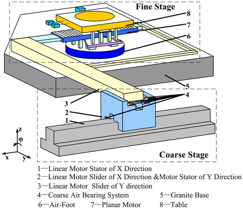
Schematic diagram of the ultra-precision positioning dual-stage system.
In the ultra-precision positioning dual-stage system, the coarse stage is used for coarse and large range motion while the fine stage for precision and small range motion. As for the coarse air bearing system, the coarse stage also has two linear motors to achieve movement in the x and y directions. Each linear motor consists of a stator and a slider. In the coarse stage, the slider of the x direction linear motor is also used as a stator of the y direction linear motor. The specific structure of the coarse air bearing system is shown in Figure 2. The linear motor stator of the x direction is fixed on the ground through bolts. The linear motor slider of the x direction is suspended in the linear motor stator of the x direction by eight air bearings and can move in the x direction. The actuator of the fine stage is a planar motor, the stator of which is linked with the linear motor slider of the y direction and suspended in the linear motor stator of the y direction by eight air bearings. Hence, the fine stage can be driven in the x and y directions. The coarse air bearing system is a combination of 16 air bearings which support the linear motor slider in the x and y directions.

Structure of the coarse air bearing system.
In Figure 1, the 3D size of linear motor stator of the x direction is 585 mm × 210 mm × 65 mm, the 3D size of linear motor slider of the x direction is 330 mm × 280 mm × 209 mm, and the length of the linear motor slider of the y direction is 900 mm. The size of the granite base is 740 mm × 566 mm × 100 mm, the diameter of air-foot is 234 mm, the orifice diameter is 0.15 mm, the length of planar motor is 310 mm, and the 3D size of the table is 288 mm × 319 mm × 33 mm.
A schematic diagram of the air-foot is shown in Figure 3. The air-foot has an annular air bearing, a circular vacuum preloading chamber, and two circular ambient pressure grooves which are used as vents. The annular air bearings have 12 compound restrictors consisting of small orifices and rectangular chambers symmetrically. Compressed gas flows through the feed holes to the chambers and then fills the air gap and flows out to the atmosphere by the vent finally. The preloading device which is at the center of the air-foot generates suction by vacuum. The advantage of vacuum preloading is that it creates a preloading force on the bearings without adding mass. As for the coarse air bearing system, the fine stage mainly consists of a granite base, a planar motor, and a table. The granite base is used to ensure the flatness of gas flow boundary. The planar motor which is supported by the air-foot can drive the fine stage to move in the x and y directions and rotate around the z direction. The workpiece requiring ultra-precision at high speed is placed on the table, which is mounted on the air-foot directly.

Schematic diagram of the air-foot.
As mentioned above, the two air bearing systems are supporting the coarse stage and the fine stage, and they will influence the performance of the ultra-precision positioning dual-stage system directly.
Dynamic modeling of the bearing system
The general form of the air bearing
Figure 4(a) shows the general form of the air bearing, which is made of ceramic or hard aluminum alloy. The air channels are processed, and the restrictor is installed inside the air bearing. In the air bearing system, the precision granite or marble table is usually used as a support base. The air bearings are placed on the support base and carry a motion stage to achieve movement of single direction or multi-directions. The air bearing working surface are the support base and bottom surface of air bearing. The air gap between the two surface is very small. When an air bearing works, the lubricating gas flows through the restrictor c into the recess of the bearing and then fills the air gap before flowing into the ambient. As shown in Figure 4(b), the air supply pressure is
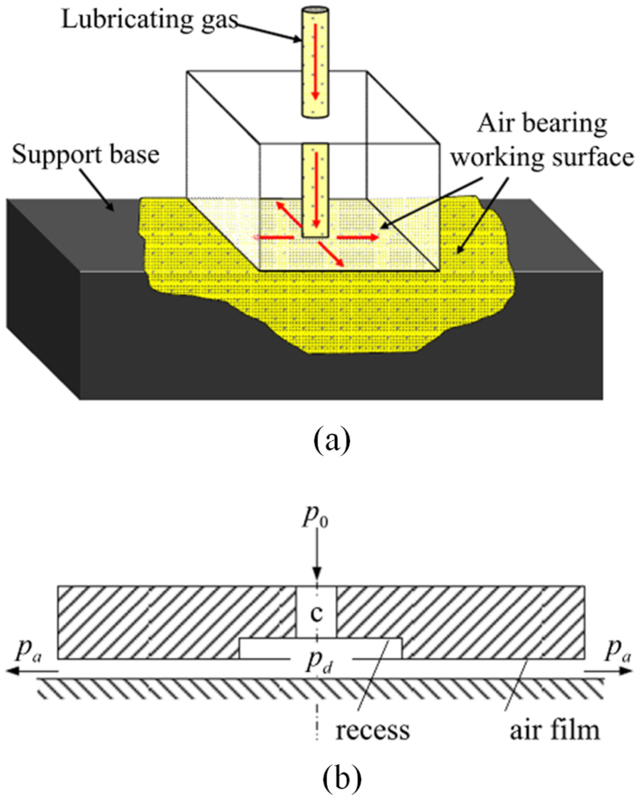
Structure schematic diagram of the air bearing.
Modeling method of the air bearing
In order to investigate the effects of small vibration of air bearing on the motion stage, a dynamic modeling method for air bearings is presented in this section. In practice, the motion stage is supported by an air bearing system composed by multiple air bearings. As shown in Figure 5, a moving part is supported on a support base by an aerostatic bearing system. The support base is denoted by body A, and the moving part denoted by body B. Define

Modeling for an air bearing system.
In the conventional multi-rigid-body modeling, the two ends of spring are fixed on the two rigid bodies, respectively. The acting positions of the spring on two rigid bodies are constant. The direction of the spring stiffness changes with the relative pose of two rigid bodies. In the air bearing, the gas film makes the supported stage move on the granite base with near zero friction. When the supported stage has planar motion on the support base, support forces are always vertical upward, and the acting positions of the spring of the support base are varying. The simplified spring in conventional multi-rigid-body modeling method is not applicable.
According to the characteristics of the air bearing, a signal air bearing can be simplified as a sliding spring which has the same direction with line

As mentioned above, a single air bearing can be modeled as a sliding spring which has only nonzero stiffness in the normal direction which represents the effect of the finite area of pressurized air. The air bearing system can be modeled as a combination of distributed sliding springs, and each one of them represents a single air bearing, which indicates three single air bearings in the air bearing system in Figure 5. As shown in Figure 6, two air bearing systems in the ultra-precision positioning dual-stage system are modeled as two sets of multiple distributed sliding springs, which represent as blue spring in this figure. In this way, the established air bearing model can reflect the tilt characteristics of actual air bearing system and can be used in the dynamic modeling of ultra-precision positioning dual stage.

Dynamic model of the ultra-precision positioning dual stage.
Dynamic modeling of the stage
In order to verify the proposed modeling method of air bearing, a dynamic model of the ultra-precision positioning dual stage is established, in which two air bearing systems are modeled using the method described in section “Dynamic modeling of the bearing system.” According to the proposed modeling method, an air bearing can be simplified as a sliding spring. In the ultra-precision positioning dual stage, the 12 air bearings of the air-foot can be simplified as 12 distributed sliding springs mentioned above, to ensure the fine stage floats on the granite base with no horizontal friction and high vertical stiffness. The 16 air bearings in the coarse air bearing system can also be simplified as 16 distributed sliding springs to support the linear motor slider in the x and y directions.
The influence of vibration caused by excitation of the air bearing system and mechanical structure dominates the performance of the ultra-precision positioning dual stage. Because these effects are within the ultra-precision positioning dual stage, the stage needs to be divided into a finite number of components. This number has to be relatively small so as to come up with a low dimensional description of the ultra-precision positioning dual stage. On one hand, this number should be as small as possible in order to keep track of the basic mechanisms causing the dynamic behavior of the ultra-precision positioning dual stage; on the other hand, this number should be large enough to be able to describe all the relevant phenomena with sufficient details. In order to be able to describe the aforementioned effects, the ultra-precision positioning dual stage is split up into four components or bodies. Body 1 contains the granite base and the linear motor stator of the x direction. Body 2 contains only the linear motor slider of the x direction or the linear motor stator of the y direction. Body 3 contains the linear motor slider of the y direction, the planar motor, and the table of the fine stage. Body 4 contains only the air-foot of the fine stage. The dynamic model of the ultra-precision positioning dual stage is shown in Figure 6. The blue springs represent air bearings, and the black springs fixed at both ends reflect the structural flexibility.
There are 24 generalized coordinates
The vibration differential equations are derived according to the Newton–Euler method. The resulting equations are in the matrix form

where M is the generalized mass matrix,
In equation (2), M,
The rigid body masses are calculated based on the shape and size of corresponding components. The structural spring stiffness is obtained through the finite element analysis of the corresponding components in the fine stage. In order to obtain the spring stiffness of air bearings, the following procedures are proposed:
According to the structural properties of the coarse air bearing system and air-foot, we establish a 3D flow model of the air bearing, set proper boundary conditions and properties of the fluid, select the appropriate solver for iterative calculation, and use computational fluid dynamics (CFD) software Fluent to obtain numerical solutions of the gas pressure distribution.
Obtain the load capability of each air bearing. The load capability can be calculated by integrating the pressure in the lubricating film area. The air bearing in the air-foot is a ring bearing, the load capacity of which can be calculated as follows
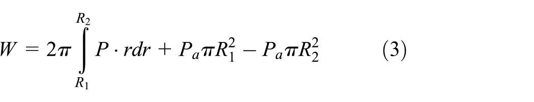
where P is the pressure in the lubricating film area,
The air bearing in the coarse air bearing system is a rectangular bearing, and its load capacity can be calculated as follows

where A is the regional area of the gas film.
3. Calculate the air bearing stiffness. According to the above steps, the load capacity W can be calculated when the gas film thickness is

There are three specifications of air bearings in the ultra-precision positioning dual stage: 12 air bearings in the air-foot, 8 vertical air bearings, and the 8 horizontal air bearings in the coarse air bearing system. Each type of the spring has the same stiffness. Through the above processes, the stiffness of a vertical air bearing and a horizontal air bearing in the coarse air bearing system can be identified as 75 and 66 N/mm, respectively. The stiffness of an air bearing in the air-foot can be identified as 100 N/mm.
The damp effect of aerostatic bearing is squeezed-film damping mainly, and its damping can be calculated by the following equation
The damping ratio of a vertical air bearing and a horizontal air bearing in the coarse air bearing system can be identified as 0.0097 and 0.0117, respectively. The damping ratio of an air bearing in the air-foot can be identified as 0.0074.
The ultra-precision positioning dual stage modeled by four bodies is represented by a 24th-order dynamic model. This dynamic model can be used for analysis in the simulation software package Simulink, by transforming it into C-code and using the so-called s-functions defined in Simulink. Besides time-domain analysis, frequency-domain analysis can also be performed.
Experiments
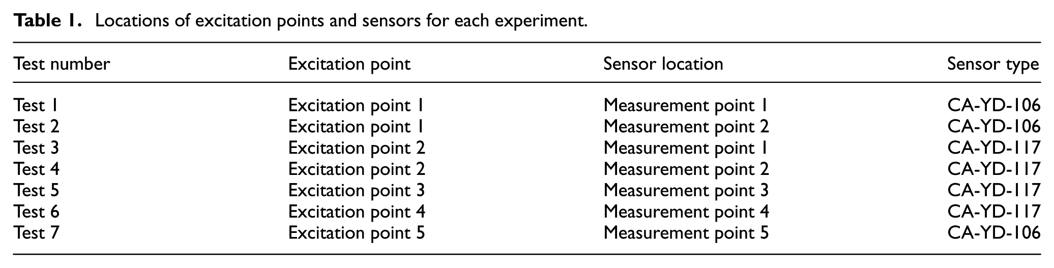
To confirm the validity of the simulation result, a series of experiments of the ultra-precision positioning dual stage are conducted. The standard drop hammer tests on specimens have been carried out. The locations of the excitation point and sensor arrangement are shown in Figure 7. In the drop hammer test, the hammer equipped with a rubber head is used, and an acceleration sensor (CA-YD-106 and CA-YD-117) is placed at the test position to obtain the vibration responses. The main technical specifications of CA-YD-106 were presented as follows: sensitivity at 20°C ± 5°C is 2.7 pC/m/s2, transverse sensitivity is 5%, maximum allowable acceleration is 1.96 × 10⁴ m/s2, frequency range is 0.5–12 kHz, and the weight of the sensor is 15 g. The main technical specifications of CA-YD-117 were presented as follows: sensitivity at 20°C ± 5°C is 50 pC/m/s2, transverse sensitivity is 5%, maximum allowable acceleration is 1.5 × 10³ m/s2, frequency range is 0.2–3 kHz, and the weight of the sensor is 50 g.

Location of excitation points and measurement points.
Seven groups of experiments are performed, each group for four times, and average data values are taken. The excitation point and measurement point for each experiment are shown in Table 1. A modal hammer (ENDEVCO 2302-10, 500 lb range, frequency range of 8 kHz, and sensitivity of 10 mV/lb) is used to supply an impulse force signal. Using modal test and analysis software LMS to collect excitation signals and response signals, with a sampling resolution of 0.5 Hz, the average frequency response functions are calculated from 20 sampling data. The experimental results for tests 1–7 are shown in Figure 8.
Locations of excitation points and sensors for each experiment.

Experimental results for tests 1–7.
In test 1 and test 2, the excitation point is located on the stator of the y direction linear motor, and the measurement points are located on the stator and slider of the y direction linear motor, respectively. The direction of excitation and measurement are in the z direction. In test 3 and test 4, the excitation point is located on the slider of the y direction linear motor; the measurement points are located on the stator and slider of the y direction linear motor, respectively; and the direction of excitation and measurement are the same as those in test 1 and test 2. The excitation and measurement points of the four tests are interchangeable; therefore, the common peak frequencies of the two frequency response functions in both tests are adopted. According to the position and direction of the excitation points, the frequencies corresponding to the vibration mode for rotation around x-axis and y-axis and translational motion along z-axis of coarse stage are relatively easy to be represented in tests 1–4. The frequencies corresponding to the vibration mode for rotation around x-axis and z-axis of coarse stage are relatively easy to be excited in test 5. The frequencies corresponding to the vibration mode for rotation around y-axis and z-axis of coarse stage are relatively easy to be excited in test 6. The frequencies corresponding to the vibration mode for rotation around x-axis and y-axis of fine stage are relatively easy to be excited in test 7. Comparison of simulation results and experimental results is shown in Table 2. It can be seen from Table 2 that the relative error ratio of the main peak frequencies is within 10%, and the simulation results of the dynamic model and experimental results are consistent. The simulation modes of the ultra-precision positioning dual stage on 78 and 128 Hz are shown in Figures 9 and 10, respectively.
Simulation and experimental modal of the ultra-precision positioning dual stage.


Simulation modes of the ultra-precision positioning dual stage on 78 Hz.

Simulation modes of the ultra-precision positioning dual stage on 128 Hz.
Conclusion
In this article, a novel dynamic modeling method for air bearing is proposed, which can simultaneously reveal the moving direction dynamics, and the tilt characteristics of bearings. The proposed method models a signal air bearing as a sliding spring with force direction determined by stator and location by the slider and models a system of air bearings as a combination of distributed sliding springs. And each spring has only nonzero stiffness along the normal axis which represents the effect of the finite area of pressurized air. An ultra-precision positioning dual stage which contains multiple air bearings is presented, and the system structure and bearing distribution are also introduced. The proposed dynamic modeling method has been applied successfully for an ultra-precision positioning dual stage which contains multiple air bearings. An analytic dynamic model of an ultra-precision positioning dual stage with air bearings is established. Model parameters of the dynamic model are obtained through the finite element analysis. Experimental results demonstrate that the proposed modeling method for air bearings is accurate and effective. The proposed dynamic model can quantitatively describe the ultra-precision positioning dual stage accurately and can be successfully used for controller design or dynamic optimization in the future.
Footnotes
Academic Editor: Mark J Jackson
Declaration of conflicting interests
The author(s) declared no potential conflicts of interest with respect to the research, authorship, and/or publication of this article.
Funding
The author(s) disclosed receipt of the following financial support for the research, authorship, and/or publication of this article: This study was supported by the Scientific Research Funds of the Educational Commission of Hubei Province (grant no. Q20151519), the Scientific Research Funds of the Transportation Commission of Hubei Province (grant no. 201472122), and the Fundamental Research Funds for the Central Universities of China (grant no. 2016PY017 and 2013QC007).