
Abstract
Recent developments of pure electric vehicles have shown that pure electric vehicles equipped with two-speed or multi-speed gearbox possess higher energy efficiency by ensuring the drive motor operates at its peak performance range. This article presents the design, analysis, and control of a two-speed automatic mechanical transmission for pure electric vehicles. The shift actuator is based on a motor-controlled camshaft where a special geometric groove is machined, and the camshaft realizes the axial positions of the synchronizer sleeve for gear engaging, disengaging, and speed control of the drive motor. Based on the force analysis of shift process, the parameters of shift actuator and shift motor are designed. The drive motor’s torque control strategy before shifting, speed governing control strategy before engaging, shift actuator’s control strategy during gear engaging, and drive motor’s torque recovery strategy after shift process are proposed and implemented with a prototype. To validate the performance of the two-speed gearbox, a test bed was developed based on dSPACE that emulates various operation conditions. The experimental results indicate that the shift process with the proposed shift actuator and control strategy could be accomplished within 1 s under various operation conditions, with shift smoothness up to passenger car standard.
Keywords
Introduction
Pure electric vehicles have many advantages, such as low level of noise, zero-emission, and easiness to operate and maintain. In comparison to fixed ratio gearboxes, two-speed or multi-speed transmissions for electric vehicles improve the efficiency of the drive motor, extend the mileage per single charge, and relieve the load condition of the drive motor and driveline components. 1 Considering the output characteristics of the drive motor, a transmission with two speeds is the most suitable choice for pure electric vehicles due to its simple structure, high efficiency, and control simplicity. 2
The studies for automatic transmissions (ATs) are mainly focused on internal combustion engine vehicle and hybrid electric vehicle, and the research on ATs for pure electric vehicle is a relatively new field. A two-speed AT for pure electric vehicles is proposed in He et al., 3 while a further scheme demonstration and theoretical analysis were needed. Huan et al. 4 introduced the basic structure, working principle, and realization process of a dual clutch transmission (DCT) in pure electric vehicles, while the shift process was not included. Gao et al. 5 studied a two-speed inverse automatic mechanical transmission (I-AMT) of pure electric vehicle 85 for its gear ratio optimization and shift control strategy. Through the coordination control of the drive motor and clutch, the time interval of torque interruption and clutch friction loss during shift process were reduced for a smooth shift. Zhang et al. 6 carried out the gear ratio optimization for a three-speed transmission of a light electric vehicle prototype and built the simulation model based on ADVISOR, in which the simulation result indicated better energy efficiency compared to conventional electric vehicles with single-speed transmission. Zhu et al. 7 designed an optimal robust speed synchronization controller for the speed synchronization of clutchless AMT systems in electric vehicles for reducing synchronization time. A clutch disengagement strategy, which is based on a drive shaft torque observer, is proposed for the shift control of AMTs in Gao et al.; 8 the clutch can be disengaged as fast as possible without large driveline oscillations. Yu et al. 9 proposed a sliding mode control strategy based on the parameter identification of the drive motor for a commercial five-speed clutchless AMT to improve the shift quality and the driving comfort. The above studies on AMT in electric vehicles are mainly related to gear ratio optimization, synchronization control, and shift control strategy development; it is a pity that there are no related design and analysis of the shift actuator for AMT in pure electric vehicles studied.
The design and optimization of shift actuator have always been the key point and difficulty in AMT developing, so is the two-speed AT for pure electric vehicles. The performance of shift actuator influences the shift quality (the ability to shift fast and smoothly under the premise of dynamic performance and driveline life; it mainly embodies on comfort) significantly. However, shift quality makes impact on shift time and the riding comfort directly and greatly. Among various types of AMT shift actuators, the electrically controlled shift actuator is simpler, quicker, and easier to control. In general, the shift actuator systems for AMT consist of a permanent magnet brushless motor, a gear or worm reducer, and a screw-nut assembly. 10 For instance, an electrically controlled actuator that integrates gear selection and gear shift was proposed by Turner et al., 11 and a drum-type electric-drive shift actuator was studied on transmission efficiency by Zhang Zhigang et al. 12 Nevertheless, there is no need for gear selection for two-speed AMT, which makes it possible to simplify the structure of shift actuator.
The two-speed AMT for electric vehicles and the shift actuator in this study have the following features: compact size lead to a lighter gearbox, an easy access to layout design, and better assembling capacity. Simple control strategy makes the electric system more robust. They are less expensive when compared to conventional multi-speed transmissions. 13 In order to validate the shift performance of the proposed two-speed transmission equipped with the shift actuator, the two gear ratios of the AMT were optimized to match the output characteristics of the drive motor and a shift control strategy was established and implemented in a prototype transmission. The prototype was tested on a test bed built on a dSPACE real-time simulation system. The test results have shown that the two-speed AMT with the proposed actuator is capable of making upshift or downshift with responsiveness and smoothness suitable for electric vehicle applications.
Structure and operation principle
The powertrain layout of a pure electric vehicle equipped with the two-speed AMT is shown in Figure 1.
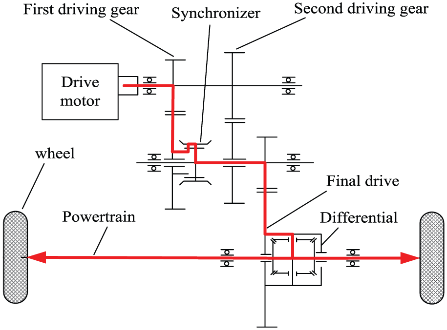
Powertrain system of AMT for pure electric vehicles.
The drive motor is directly connected to the transmission by spline instead of a traditional clutch. This structure integrates the drive motor, gearbox, final drive, and differential in a compact assembly, which helps to save space and reduce cost.
Shift actuator is the key mechanical device that influences the shift quality of the gearbox. The shift actuator of the two-speed AMT mainly consists of the shift fork (machined with a round pin), fork shaft, camshaft (machined with a groove), worm gear, and shift motor, with the three-dimensional model and schematic diagram illustrated in Figures 2 and 3, respectively. During shift process, the shift motor rotation is transformed into the axial motion of the shift fork through the worm gear drive and camshaft, so that the synchronizer sleeve can be moved along the axial direction for the disengagement of the current gear and the engagement of the coming gear.

Three-dimensional model of the shift actuator.

Schematic of the shift actuator.
The shift fork is pushed by a groove in the camshaft, as shown in Figure 4, and the expanded view of the groove is shown in Figure 5. The shift fork position control is the key to ensure the shift quality in the control system of electrically controlled AMT, and the position is reflected by the camshaft rotation angle measured by an angular displacement sensor. In order to allow for errors in the shift control process, the groove is machined with an extra length at both ends. As shown in Figure 5, the groove is divided into five parts, including the rotation angle part of the first gear (part 1), the first gear slope (part 2), the rotation angle part of the neutral (part 3), the second gear slope (part 4), and the rotation angle part of the second gear (part 5). When the shift fork pin is at a rotation angle part of the groove, the shift fork cannot move in the axial direction, although the camshaft is rotating, which guarantees the control accuracy of the key positions in the shift process.

Camshaft rotation diagram.
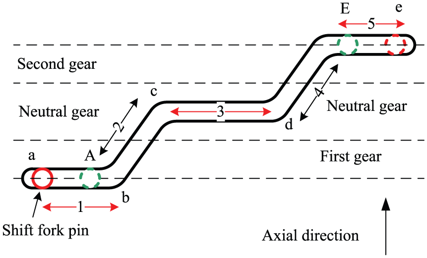
Expanded view of the groove in the camshaft.
Parameter design of shift actuator
For the two-speed gearbox in this article, the shift actuator design must satisfy the requirements listed in Table 1.
Design requirements of the shift actuator.

The shift actuator consists of the power source and the reduction mechanism. The power source is the shift motor whose major specification is the rated power. The design requirements in Table 1 can be satisfied by matching a reduction mechanism with an appropriate gear ratio, when the rated power of the shift motor meets the requirements of the shift actuator. The reduction mechanism includes the shift fork, fork shaft, camshaft, and worm gear, and the main parameters are the cam radius, the lead angle of the groove, and the reduction ratio of the worm and worm gear.
Parameter design of shift motor
In the shift process, the main loading conditions occur at the two slopes of the groove (parts 2 and 4 in Figure 5) corresponding to the gear engagement or disengagement. The force analysis of the shift fork is illustrated in Figure 6, where the shift fork pin moves along the slope.
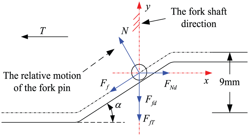
Force analysis of the shift fork.
In Figure 6, T is the torque on the camshaft transmitted from the shift motor; N is the force applied on the fork pin by the slope due to the camshaft torque; Ff is the friction between the slope and fork pin; FfT is the resistance from the synchronizer sleeve against the shift fork motion, and the maximum value of FfT is 300 N (shown in Table 1); Ffd is the friction between the fork shaft and the shift fork; FNd is the contact force between the shift fork and the fork shaft; and
For the force analysis in Figure 6, the following equations must be observed


where
The shift fork slides on the fork shaft which is fixed on the transmission housing, making the moving in x-direction impossible. So the forces are balanced in x-direction

For the shift fork to move along the fork shaft, the following equation must be satisfied

Combining equations (1)–(5), we can determine the minimum output torque of the shift motor required to move the shift fork as follows
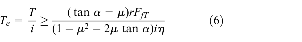
where
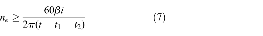
In conclusion, the output power of the shift motor can be determined by combining equations (6) and (7), as the following equation

As shown in Figure 6,

All variables except


Relationship between rated power of shift motor and lead angle of groove.
In order to ensure the smoothness of shift, a permanent magnet direct current (DC) motor is employed for the shift actuator in this study. The rated power of the motor is 35 W, and its rated speed is 2500 r/min and rated torque 0.134 N m.
Parameter design of reduction mechanism
The design parameters of the reduction mechanism consist of the cam radius, the lead angle of the groove, and the transmission ratio of the worm and worm gear. The lead angle of the groove in the camshaft is calculated in the last section to be
As the force analysis of the shift fork illustrated in Figure 6, the shift force is determined as follows

The total shift time is

where

The range of the ratio i/r obtained based on equations (11) and (13) is as follows

The shift fork contacts with the camshaft groove by a round pin, so the contact area between the round pin and the groove is a line. This may yield high contact stress. In order to extend the contact line, the cam radius should be enlarged, and the camshaft groove should be deeper. The cam radius should be about 0.018 m with the inner space limitation of the gearbox. Then, the transmission ratio of the worm gear is limited in the following range

In this study, the transmission ratio of the worm and worm gear is chosen to be 66.
Shift control strategy
Control principle
Control logic for conventional AMT mimics a skilled driver, with the shift process divided into seven steps, including driving in the original gear, separating clutch, disengaging the original gear, selecting the target gear, engaging the selected gear, engaging the clutch, and driving in the new gear.
For conventional AMT, there is a clutch that works in the shift process. When the vehicle drives under certain ratio, the AMT controller estimates whether another ratio should be adopted based on the vehicle speed, throttle opening, and current operation status. If a shift is to be made, the throttle opening will decrease, and the clutch will be separated. When the clutch separation is completed, the gearbox will be shifted to neutral. The next gear is then selected and engaged. The clutch is then reengaged and the vehicle drives under the new transmission ratio. Shift smoothness depends on the clutch separation and reengagement to a large extent.
In this study, no clutch is equipped in the two-speed AMT, and the motor is directly connected to the transmission by a spline. Since the motor is connected during shift process, the mass moment of inertia to be synchronized includes the motor itself and the input shaft. This combined mass moment of inertia is larger than that in conventional AMT. Moreover, the speed difference between the two gears is much higher than that in a multi-ratio AMT. Therefore, it is crucial to coordinate the drive motor speed, torque, and shift actuator in order to realize smooth shifts.
The framework of shift control for the two-speed AMT for pure electric vehicles is shown in Figure 8. The signals between transmission and motor are transmitted by the controller area network (CAN) bus each way.

Signal flow for shift control.
Shift control process
As mentioned previously, the two-speed AMT is not equipped with a clutch. Therefore, to achieve smooth and quick shifts, it is essential to control the speed of the drive motor during shift process. The drive motor operates under the torque control mode when the vehicle drives at either first or second speed. In order to make smooth shifts, the drive motor will be switched to free mode from torque mode as soon as a shift is initiated. Then the output torque of the drive motor is reduced to 0 immediately. After the shift fork reaches the neutral position, the drive motor will be switched to the speed control mode. The speed difference between the driving part and driven part of the synchronizer will be decreased to an infinitesimally small value through the speed control of the drive motor, and the residual speed difference will be fully synchronized mechanically by the synchronizer itself. Then the drive motor will be switched back to free mode. When shift is finished, the drive motor will be back to the torque mode and the output torque will be recovered as driver expects.
The shift fork of the shift actuator is driven by the camshaft groove, and the geometry of the groove is shown above in Figure 5. The shift stroke corresponds to parts 2 and 4 in the shift process and the shift fork has no axial motion when the camshaft rotates through these three idle parts 1, 3, and 5. This feature eliminates the errors in the control process by mechanical structure, so the control strategy is simpler and the shift process control is more reliable. However, the idle sections would impact the shift time, which should be minimized in the shift control strategy development.
In conventional control strategy, the control for the position from the current gear to neutral and the speed control of the drive motor is sequential. Namely, the drive motor speed control starts after the shift fork reaches neutral position c. The camshaft groove is designed with a long flat neutral part 3, so the shift fork position control and the speed control of the drive motor can be coordinated parallelly. Namely, the drive motor speed control can be started until the shift fork moves close to the position d of part 3. If the speed control of the drive motor is completed at this time, the shift fork goes directly to shift to target gear; on the contrary, it waits for the completion of the speed control. The flowchart for the shift process control is shown in Figure 9.
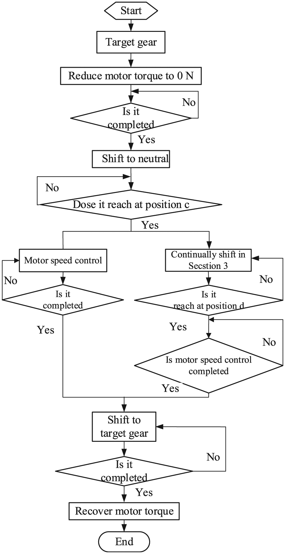
Flowchart for shift control process.
Drive motor torque control strategy before disengagement
The degree of shock j is an important index for evaluating shift quality, decided by the changing rate of longitudinal acceleration

where R is the radius of the tire,
Before shift process begins, the output torque of the drive motor has a certain relationship with the drive torque of the drive wheel, so the degree of shock can be defined as

where
From equation (17), the impact generated before shift starts is directly proportional to the change rate of the drive motor torque. When receiving the shift signal, in order to achieve a rapid disengagement, the drive motor torque must be declined to 0 (the drive motor is in free mode state). So if the controlled torque of the drive motor is decreased directly to 0 when the drive motor is switched from its torque mode to free mode, there would be a massive impact, which will degrade the drive comfort greatly. Therefore, the change rate of the drive motor torque should be controlled precisely, for reducing the shift impact and promoting drive comfort.
Combining equation (16) with equation (17) yields equation (18)

According to the Germany standard, j≤10 m/s3; based on this, we can get the largest change rate of the drive motor torque. Before disengagement, the torque of the drive motor should decline by the calculated changing rate which satisfies the shock requirement.
Speed governing of drive motor before gear engaging
As soon as the drive motor is in free mode state, the off-going gear is disengaged at the shift actuator’s maximum speed until the gear is in the neutral position sequentially. To ensure engage successfully and decrease the shock during engagement, the speed difference between the driving part (synchronizer sleeve) and driven part (joint ring gear) of the synchronizer should be decreased through the drive motor’s speed governing.
The simplified dynamic model of the powertrain is shown in Figure 10 for the synchronizing process. It shows that if the speed of the driving part

Dynamic model for synchronization process: (a) speed of engagement sleeve is lower than the speed of joint ring gear ω1 < ω2 and (b) speed of engagement sleeve is higher than the speed of joint ring gear ω1 > ω2.
The target speed for the speed control of the drive motor in the shift process should be

where
Shift actuator control strategy in gear engaging process
In this study, the two-speed transmission is equipped with an inertial synchronizer. During gear engaging process, the synchronizer ring is driven by the friction torque and rotates a relative angle to the synchronizer sleeve quickly. If the gear engaging is too fast, this rotation would make the sleeve skip the synchronization between the sleeve and synchronizer ring, while mesh with the joint ring gear directly, resulting in gear grinding and shift impact.14,15 Based on the analysis above, in order to avoid gear grinding, the relationship

Components and dimensions of inertial synchronizer.
On the basis of analyzing above, the equation becomes


where v is the moving speed of the synchronizer sleeve,
According to the requirement of avoiding gear grinding during synchronization

In equation (22), we can know that since synchronization starts, the shift actuator should be controlled to make the speed of the synchronizer sleeve smaller than
When
Drive motor torque recovery control strategy after shift finished
In actual vehicle operation, the driver’s intention can be best reflected by the accelerator signal. So in this article, in order to reach the goal of intelligent drive motor’s torque recovery, accelerator opening and its change rate are selected as the arguments to interpret the driver’s current intention, which determines the way how torque recovers. As the driver’s intention is of empirical nature, it is difficult to describe the driver’s intention with an accurate mathematical model. Therefore, fuzzy control is used to reflect the intention of the driver. The latest method for the interpretation of the driver’s intention is usually to classify the driver’s intentions under various operations in specific environments and extract the characteristics of such operations and then establish a qualitative scheme using fuzzy nearness or fuzzy reasoning.16,17
Establishment of fuzzy control system for torque recovery
Input and output variables
At the end of shift for the two-speed transmission, the input linguistic variables of fuzzy control for the torque recovery of the drive motor are the accelerator pedal opening
Fuzzification of linguistic variables
Considering the dynamic performance requirements intended by the driver under different driving conditions, the variable linguistic values are classified in the following. There are five levels for the accelerator pedal opening, small (S), middle small (MS), middle (M), big (B), and very big (VB). There are four levels for the change rate of the accelerator pedal opening, negative (N), small (S), middle (M), and big (B), and there are three levels for the torque recovery rate coefficient, small (S), middle (M), and big (B).
Curve of membership function
The triangle and the trapezoid are selected as the membership function of the fuzzy subset, where the trapezoid can be seen as a triangle with a cut head. With simple mathematical expression and operation, the triangle and the trapezoid have better sensitivity than the membership of normal distribution or bell distribution when the input value changes. This means a corresponding output regulation can be generated more responsively when there is an input deviation.
According to the basic principles of the above membership function and the practical experience, the membership function for the input linguistic variable of the accelerator pedal opening, its change rate, and the membership function for the output linguistic variable of the torque recovery rate coefficient of the motor are designed as shown in Figure 12(a)–(c), respectively.
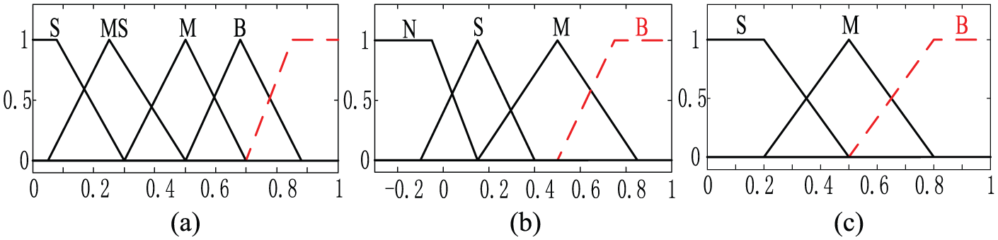
Membership function of input and output: (a) membership function of the accelerator pedal opening, (b) membership function of the accelerator pedal opening change rate, and (c) membership function of the coefficient K.
Fuzzy reasoning
The fuzzy control scheme is that the driver’s intention is reflected by the accelerator pedal opening and its change rate. The large accelerator pedal opening and its change rate indicate great power demand of the driver; then fast torque recovery of the motor is required and the Chinese standard on jerk level j should be adopted,
Based on the above fuzzy control scheme, the control countermeasures of every specific condition are summarized as a control rule expressed by fuzzy condition. And some fuzzy conditional statements with different linguistic values are demanded to form the complete control rules, as shown in Table 2.
Fuzzy rules of the coefficient K.
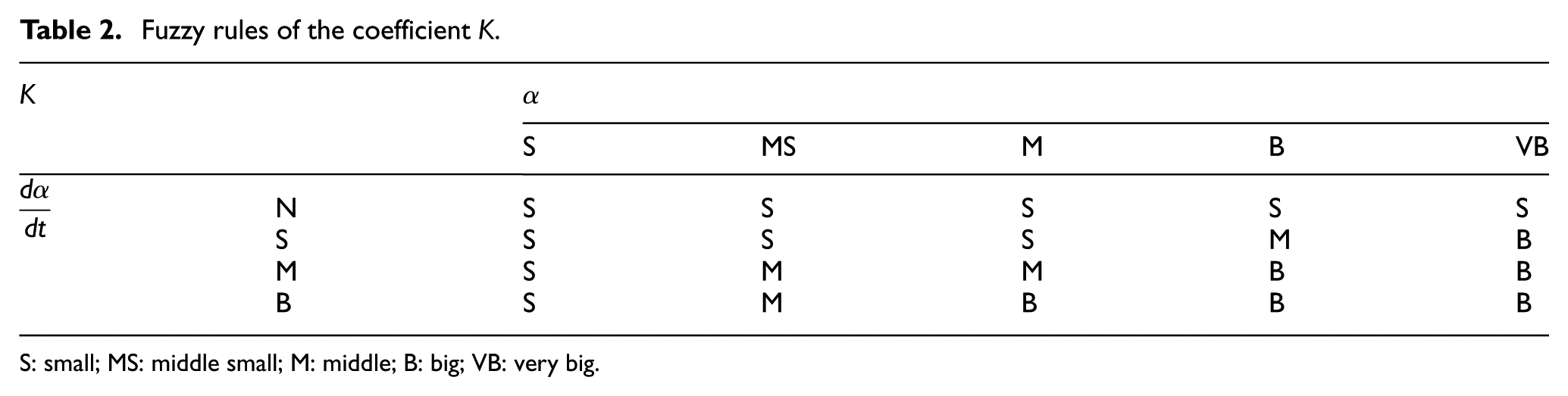
S: small; MS: middle small; M: middle; B: big; VB: very big.
Fuzzy decision
For the reason that only one control variable can be accepted by the control object, it is necessary to determine an accurate control variable from the fuzzy subset of output, namely, the mapping from the fuzzy set to the normal set.
The fuzzy inference system (FIS) editor of the MATLAB fuzzy logic toolbox is used to define the entire fuzzy system and the Mamdani method is adopted for the fuzzy reasoning. This includes the realization of operators of OR and AND with Max and Min, respectively, the implication relationships with Min, the combination rules with Max, and the defuzzification with gravity method, as shown in Figure 13.

Three-dimensional map of fuzzy reasoning.
Torque recovery strategy
To reflect the actual operation conditions of the vehicle actually, a torque recovery curve is proposed based on the actual response characteristics for torque command of the drive motor, as shown in Figure 14.

Revised torque recovery strategy of the drive motor.
The figure displays that the proposed recovery curve is actually stepped, which stands for that the target torque value is transmitted in accordance with the step signal and the purpose of intelligent torque recovery is achieved by controlling the number of steps. Through this experiment, the target torque is achieved with two steps in the condition of high power demand and is achieved with many steps in the condition of high comfort demand. In order to ensure the torque recovery time, the final target torque is achieved up to four steps in this study.
In view of the above analysis, the torque recovery curve is a modified step curve, while the number of the steps is determined by the intention of the driver interpreted by the fuzzy control. Figure 15 is the top view of the three-dimensional results for fuzzy reasoning. The yellow part represents the power demand and the blue part indicates the comfort demand, while the transition part of the yellow and blue represents both power and comfort demand.

Top view of the fuzzy reasoning result.
Thus, based on the modified torque recovery curve, the yellow part should be two steps (n = 2), the transition part should be three steps (n = 3), and the blue part should be four steps (n = 4). Combined with the fuzzy results, it is defined, respectively, as
Test results’ analysis
In order to verify the performance of the two-speed AMT equipped with the shift actuator, a prototype was developed and a test bed was set up based on dSPACE real-time simulation, as shown in Figure 16. The test bed is composed of the power source, the two-speed transmission prototype, speed-increase gearbox, fly-wheel, dynamometer, data acquisition system, and measurement and control system. The architecture of the test bed is shown in Figure 17 and the main component parameters of two-speed AMT are shown in Table 3.

Prototype and test bed of the two-speed AMT.
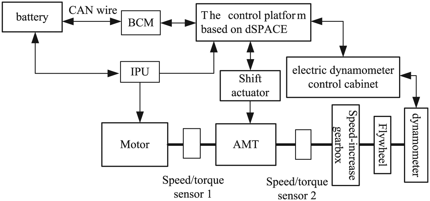
Architecture of the test bed for pure electric vehicles.
Main component parameters of two-speed AMT.

DC: direct current; AC: alternating current.
Shift test in normal condition
Upshift test
In upshift test, the accelerator pedal opening is set at 20%, and the change rate of the pedal opening is set at 80%. The shift speed is 21 km/h, and the initial gear is the first gear. The test results are shown in Figures 18 and 19.

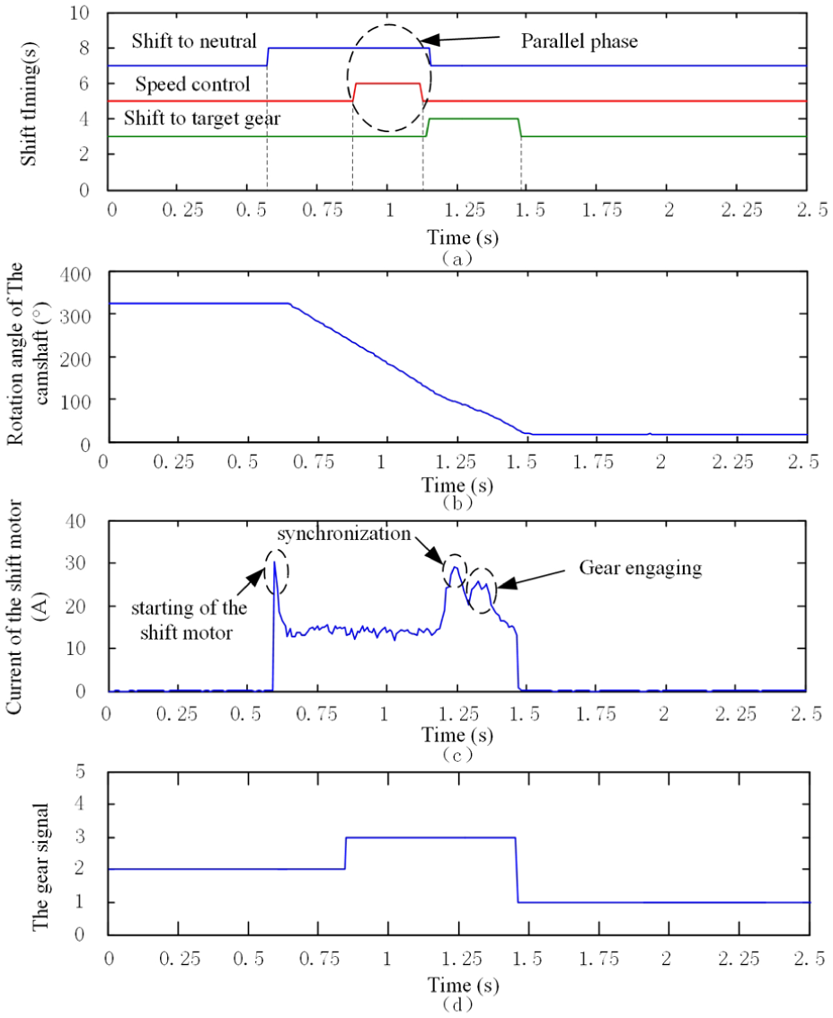
Comprehensive control sequence of upshift.
Detailed results of upshift test.
The rotation angle of the camshaft is acquired by an angular displacement sensor, and the sensor output is shown in Figure 18(b). The curve in Figure 18(c) represents the shift motor current, whose value is in proportion to the output torque of the shift motor. The gear signal is shown in Figure 18(d). 1, 2, and 3 stand for the first gear, second gear, and neutral, respectively.
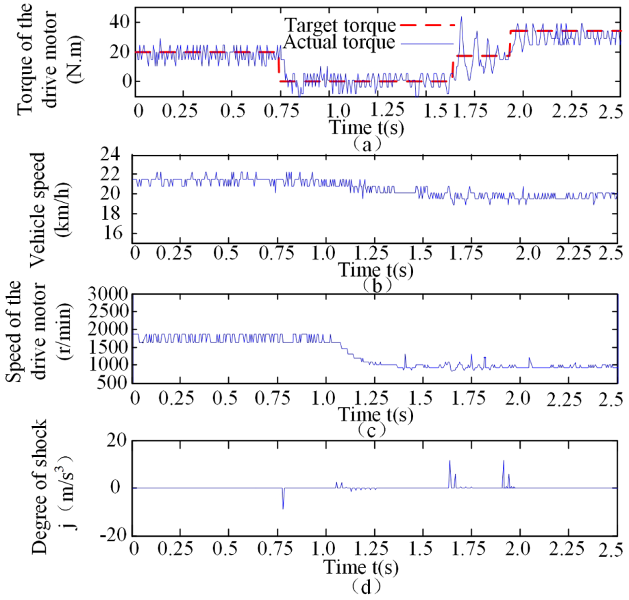
The test results show that the upshift can be achieved by adopting the proposed shift control strategy. In the upshift process, the total shift time is 0.88 s, and the torque recovery needs 0.35 s. The sequence of various stages in the shift process is shown in Figure 18. The process from the start of shift to the end of motor speed control needs 0.49 s. The motor speed control needs 0.22 s and the parallel time is 0.22 s. The process from the end of motor speed control to the end of gear shift needs 0.39 s. A certain time is needed for communication among the system components. Specifically, it is 0.02 s between two adjacent shift phases. As shown in Figure 19, the vehicle speed is basically stable, and the torque recovery is achieved in accordance with the established strategy in the upshift process. The jerk of the whole shift process is controlled in the range of 17.64 m/s 3 , which meets the standard.
Downshift test
In downshift test, the accelerator pedal opening is set at 20%, and the change rate of the pedal opening is set at 80%. The shift speed is 15 km/h, and the initial gear is the second gear. The test results are shown in Figures 20 and 21.
Comprehensive control sequence of downshift.

Detailed results of downshift test.
The test results illustrate that the downshift can be achieved by adopting the proposed shift control strategy. In the downshift process, the total shift time is 0.92 s, and the torque recovery needs 0.45 s. The sequence of various stages in the shift process is shown in Figure 20. The process from the start of the gear shift to the end of the motor speed control needs 0.54 s. The speed control time is 0.25 s and the parallel time is 0.25 s. The process from the end of the motor speed control to the end of the gear shift needs 0.38 s. As shown in Figure 21, the vehicle speed is basically stable, and the torque recovery is achieved in accordance with the established strategy in the downshift process. The jerk of the whole shift process is controlled in the standard range.
Comparison test of torque recovery
In this test, with the upshift process as an example, the accelerator pedal opening is set at 20%, and the change rate of the pedal opening is set at 40%. The shift speed is 21 km/h, and the torque recovery curve and jerk in this condition are shown in Figure 22.
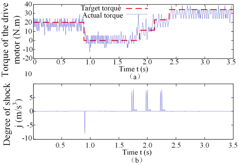
Torque recovery curve and jerk with
As shown in Figure 22, when the change rate of accelerator pedal opening is 40%, the jerk is reduced to below 10 m/s 3 , which is lower than the jerk in the change rate of 80% (Figure 18). This farther indicates the effectiveness of the torque recovery strategy based on the identification of the driver’s intention by fuzzy decision.
Conclusion
In this article, the design, analysis, and control of a two-speed AMT for pure electric vehicles were investigated. The following highlights the results of the study:
A brand-new shift actuator was designed to meet the requirements of gear shift based on the analysis of the characteristics of the two-speed transmission. The parameters of the power source and reduction mechanism for the shift actuator were designed based on the force analysis in the shift process.
Based on the control principle of electric vehicles and the analysis of the shift actuator characteristics, drive motor’s torque control strategy before shifting, speed governing control strategy before engaging, shift actuator’s control strategy during gear engaging, and a torque recovery strategy after shift process were proposed for the two-speed transmission to achieve a better shift.
A two-speed transmission prototype was developed and a test bed was set up based on the dSPACE real-time simulation for the evaluation of the design and control strategy. The experimental results indicate that the gear shift can be finished responsively and smoothly within 1 s regardless of upshifts and downshifts. In terms of the experimental data, the shift actuator meets all the design requirements.
Footnotes
Appendix 1
Academic Editor: Mario L Ferrari
Declaration of conflicting interests
The author(s) declared no potential conflicts of interest with respect to the research, authorship, and/or publication of this article.
Funding
The author(s) disclosed receipt of the following financial support for the research, authorship, and/or publication of this article: This research was supported by the Chongqing Natural Science Foundation (project no. CSTC2015jcyjA 60005). This project offered all the cost of this series researches. The authors appreciate for its support on these researches.