
Abstract
The functional structure information of a design history is analyzed to capture product design intent information, which is significantly important for the rapid and efficient solving of local demand-varying designs. Based on the intent capture and reuse issues of the design histories of existing products, this study proposes the use of the effectual action unit–based inverse method to solve the functional structure of design history. Effects are regarded as an intermediary between functional requirements and principle solutions of design history. After the effectual action unit model is built, function unit synthesis could be constructed by effect function between the input and output parameters. The functional structure frame of design history is obtained by constructing the design history structure–principle–effect–function inverse solving model. The prototype system of the inverse solving of the functional structure of the complex electromechanical product-oriented design history is developed in this study. Moreover, the feasibility of the proposed method is verified using a new laptop as an example. Overall, design intent of design history can be described by the proposed method.
Keywords
Introduction
Design is vital to the key competitive factors of a product, such as performance, cost, quality, and reliability. 1 With respect to product design alone, demand (or design requirements) is the original driver and decisive factor of design. Any slight demand change will change the product functions as well as principles of function implementation, thus forming a new original understanding. This article defined these designs as local demand-varying designs. In the real world, local demand-varying designs are more common than original designs. For example, many famous automobiles require both new design demands or local varying demands and inherent features of the brand superiority in historical designs in most of their new cars. The varying local demands need innovative design again. Many complicated technical products adopt these local demand-varying designs. Therefore, local demand-varying designs require designers to apply innovation on the variable part based on a good understanding of referential design history. However, how to understand the “design intent” in design history and extract characteristics than can be transplanted or reused according to the functional demands of the new design? Although these characteristics have been attached to the final design, they can’t be applied in the new design directly due to the ambiguous function carriers. This is especially correct to complicated technical products. Since designers have no mature methods and tools to understand the “intent” of the original designs or enterprises didn’t record the design process of available referential product design history, some functions or structures of these products can’t be transplanted to the new design directly. As a result, an inverse model of the design principle and functions of available referential product design history has to be established for the sake of future similar new designs.
Local demand-varying designs, such as the generally accepted adaptive design and the variant design, 2 occupy an important position in the field of product design. However, the variable part of the demands of a local demand-varying design needs an innovative design. Local demand-varying designs require designers to apply innovation on the variable part based on a good understanding of referential design history. In other words, designers should solve some new problems different from the completely innovative design or adaptive design. Capturing the design intent of the original product is the most important problem because the part that will be used for the new design can only be stripped from the complex product when the design understands the intent of the original design. 3 Most enterprises have deficiencies in the information management of available referential product design history and they lack correct and valid understanding of product design history intent, which makes the application of existing product design history in new demand-varying design not difficult.
Existing pervasive design model based on design demand-functional modeling-functional decomposition-solution of functional principle-detailed structural design focuses on the creation and integration of function-oriented design with fixed demands, which is actually a positive design solving process with fixed procedure and fails to capture the intent of the original designs. Other mainstream design theories and methods, such as axiomatic design, 4 Theory of Inventive Problem Solving (TRIZ), 5 and three-stage designs, 6 can only provide solutions and mapping method to functions or parameters, but can’t apply their design process to capture the design intent.
Function is the core of product design, particularly of early project design, and it is also the bond that connects design demands and design results during the entire process. 7 Most previous studies skipped function to directly construct a structure-level product model associated with demands. These studies attempted to model using the product family and the attributes of the parts, and consequently resolve the demand-varying response issue. However, the function of the product is directly related to the demands, and thus, conducting research on the function-level demand-varying response is necessary to comply with the requirements of design theory. An old design should conduct function variation by reusing the design history to enable the functional structure of the design history after variation to adapt to the changes in the demands of new design. Therefore, research on obtaining the functional structure of the product by analyzing the information of the original design history will play an essential role in new demand-varying designs.
In the conceptual design with function as the core, the functional structure modeling is a very crucial step throughout the entire design process.8,9 Stone and Wood 10 proposed the abstract expression issues in establishing the functional group model. The functional group included eight functional units, namely, branch, orientation, connection, control of size, conversion, supply, signal, and support. The functional group also included three types of energy flow, which included material flow and signal flow, characterizing the function input and output, respectively. Zhang et al. 11 and Zou et al. 12 applied the functional group model to the product concept design to assist in the establishment of the functional structure of a product. Nagel et al. 13 realized the automatic generation of the product concept based on functional group modeling. To better achieve the design solving with function as the core, the research on functional modeling focuses on the realization process from the function of the product to the principle program to the final structure, in which the function–effect–principle solution model is one of the hotspots. Cao et al. 14 and Yan and Jiang 15 constructed the mapping model of the function, effect, and principle solution and then applied it to the concept design phase. Shuai et al. 16 and Feng and colleagues17,18 developed the knowledge base of related typical function and principle solution, presented the character model of the principle solution of the product, and proposed the general process of the product function solution. Feng et al. 19 introduced a computer-aided concept design process model with the product function, effect intersected and circulated for solution, suitable for the demands of the complex concept design solution process. Function modeling is a typical forward solving process that can only start from the function and then gradually find the design solution. Function modeling is suitable for a completely innovative design, but it cannot solve the inverse solution of the functional structure in local demand-varying designs.
Function structure mapping is a key link in the design of the solution. Paul and Beitz 8 proposed morphological matrix, through which principles of all sub-functions are combined. The two design theories answer the question “function is realized through structure.” Function behavior structure model2,20,21 considered behavior as expected structure dynamic characteristics.
According to different sources, the design intent can be divided into two types. The first type refers to a designer’s purpose, decision, and design basis during the design. The second type refers to the intent of the designer implied in the design process. Most existing design intent capture methods capture the design intents at different stages through the design intent modeling and then apply these design intents to the new designs. Ishino and Yan 22 defined the design intent as the design standard and scale decided by the designer during the design process to complete the entire design, to construct the intent estimation model of the design process, and to capture the design intent by determining the weighting function of various performances. Xu and Galloway 23 defined design intent as the constraints and goals defined by the designers in computer-aided design (CAD) and the optimal design solution obtained through behavioral modeling to capture the design intent and to make repeated comparisons on the design results in accordance with the design intent. Kim et al. 24 proposed the full consideration of design intent elements, such as structure, parameter, and characteristic, during data conversion of the CAD model. Li et al. 25 proposed a new method for capturing the design intent using symmetry in the approximated CAD model. Sun and Liu 26 presented a detailed description of design intent, proposed the design thinking process model, and recorded the designer’s design steps, decisions, and design bases involved in the design process.
Most recent studies on design intent capture have been conducted with the design process and design intents that are formally expressed through modeling. Such design intent capture cannot effectively support the re-excavation of the design history intent of the original products in the process of local demand-varying design. The effectual action unit–based inverse method of solving the functional structure of the design history proposed in this study starts from the product design history structure to obtain the functional structure of the product and mine its design intent, thus providing a better support for the innovative design of the local variable demand.
Based on the above analysis, this study proposes the concept of the effectual action unit. This concept will be the basis of a design history structure–principle–effect–function inverse solving method, which will be used to obtain the structure of the product design history. Then, the functional structure of the product is obtained through analysis, combination, and other ways to provide important methods for the new local demand-varying design of products.
Modeling for the inverse solution process
Effectual action unit model
Action unit, which can be uniquely identified, is an entity unit that takes a part/material as the center, expresses the mutual relations between actions, and describes the conversion information of the energy, material, and signal involved in the actions.
In this study, the input and output flows in the action units are converted into specific input and output parametric flows. The effect will be determined and introduced to the action unit according to the input and output parameters, as well as the mutual relationship between action units to form the effectual action units.
The effectual action unit includes five elements, namely, M = {P, A, of R, C, e}, where P is the knowledge set of the parts/materials of the action subject for describing the unit part/material; A is the action knowledge set for describing the unit action; R is the relation knowledge set for expressing the functional relations between the action units; C is the conversion knowledge set for expressing the conversion information of the energy, material, and signal parameters in the action units; and e is the effect knowledge set for expressing the effect information related to the energy, material, and signal parameters in the action units. e describes a single physical effect in a product, which is described by a qualitative physical law. It is therefore possible to formulate e as follows
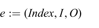
Index is used to characterize a single effect element type. I is an input parameter knowledge set, which is used to describe the input parameters. O is the output parameter knowledge set, which is used to describe the output parameters.
In Figure 1, Aj represents the central action; A1, A2, A3, and A4 represent each relevant action; Pi, P1, P2, and P3 are the corresponding parts or materials of each action; R1, R2, R3, and R4 are the functional relations among units; e1, e2, e3, and e4 are the effects related to the energy, material, and signal parameters in the action units; M1 and M2 are the input and output material parameters, respectively; S1, S2, and S3 are the input and output signal parameters; and E1, E2, E3, and E4 are the energy parameters.
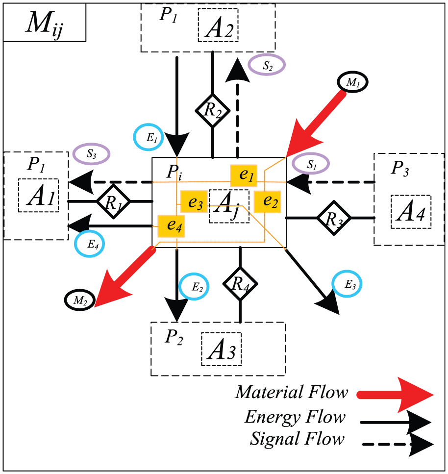
Effectual action unit.
Design history structure–principle inverse solution process
Figure 2 shows the specific steps of the overall solution design idea of the design history structure–principle.

The overall solution ideal of design history structure–principle.
Construct the structure-based model of the design history. First, search all parts of the design history (the parts in large numbers can be decomposed into several large modules) and then establish the design structure matrix (DSM) models of energy, material, signal, and space relations among parts. Table 1 shows the DSM, where P represents the element identities of various parts and 1 the correlation between two elements. Second, construct the networks of the contacts of the related energy, material, signal, and space according to the relationship between parts created by the DSM. Third, integrate all networks of the contacts according to the mainstream relationship of the design history itself to form the structure-based model. Finally, conduct size generalization (remove the details and extract the skeleton), shape, quantity, position, range, and connection conversions, as well as multi structures normalization, and then obtain several structure bases.
Design structure unit matrix.

Build the combined action unit. First, obtain each action unit model according to the modeling method of the action units. Second, determine the overall energy, material, and signal conversion flows after analysis, as well as the structure-based mainstream (energy flow, material flow, and signal flow determined by the product itself). Finally, combine and connect the action units according to the energy, material, and signal flows to form the combined action unit of each structure base.
Build the structure-based conversion relationship diagram based on the effectual action unit. First, convert the input and output flows in the combined action units of each structure base into the specific input and output physical parameters. Second, determine the effect and introduce it to the action unit according to the relationship between the input and output physical parameters, as well as the mutual relationships among the action units. Finally, connect each effectual combined action unit mutually according to the mainstream of the structure base to obtain the structure-based conversion relationship diagram based on the effectual action unit. Figure 3 shows the solving process of the structure-based conversion relationship diagram based on the effectual action unit.

The solving process of the effectual action unit–based conversion relationship diagram.
Construct the principle solution framework diagram. First, construct the form of the principle solution according to the internal action form of each action unit, as well as the effectual relations between the input and output parameters in the action unit. Second, combine the forms of the principle solution of each effectual action unit to form the combined principle solutions of each structure base according to the functional relationship between the action units in various combined action units, as well as the relationships among the parameters. Finally, connect the combined principle solutions to obtain the overall flowchart of the principle solution of each structure base.
Design history principle–effect–function inverse solution process
First, construct the effect transformation and the effect synthesis. Then, take the effect as the middle transformation link between the principle program and the function by constructing the function-based model. Finally, solve the product functional structure with the effect unit and the logical relation in the effect synthesis as the constraints.
Figure 4 shows the steps of the overall solving idea.

Design history principle–effect–function inverse solution process.
Build the effect synthesis. First, extract the effects in the effectual action unit–based conversion relationship diagram and then cluster them to obtain different effect chains according to the relationship between the input and output flows. Finally, determine the main effect chain for the effect synthesis.
Construct the principle solution unit. Construct the principle solutions corresponding to the effect units. The stored information includes effect information, effect-related input and output parameters, effect-related part structure information, and effect-related action information.
Construct the function unit synthesis. First, deduce the possible function units of the original link units corresponding to the information stored by each principle solution unit, as well as the eight categories of function base forms. Then, determine the logistic relationships among the function units, as well as the main function unit chain, according to the mainstream of the structure base. Finally, integrate various vice-function unit chains into the main function unit chain according to previously obtained function unit chain relationship.
Generate the functional structure framework. Consider the aforementioned function units in three aspects. First, merge the related function units to form the sub-functions. Second, replace the generalized function expressions with more technical ones. Third, organize the relationships among functions to form the function structure framework of the corresponding structure bases.
Example validation
Based on the inverse solving the functional structure theory discussed above and given the design history of a new laptop as background, a prototype system of the functional structure inverse solving of the design history of complex electromechanical products is realized. Figure 5 shows the block diagram of the inverse solving process of the new laptop. The prototype system is implemented with Microsoft Visual Studio 2010 and database of the system is developed by SQL Server 2000. Table 2 shows the database tables of the prototype system.
Step 1: Organize the design history information. Build the three-dimensional model of the product and part knowledge base, the action knowledge base, the functional relationship knowledge base, and the conversion relationship knowledge base as basic information of the following inverse solving process.
Step 2: Build the design history structure base model. Given the parts, functional relationship, and conversion relationship knowledge bases as bases in the design history information, construct the DSMs, relationship network diagrams, and structure bases of the laptop using the structure base construction method. Finally, consider the related structures in the structure base to obtain two structure base models, namely, the keyboard disassembly and assembly and the host moving and locking. The following steps will be explained with the structure base-keyboard disassembly and assembly as the example.
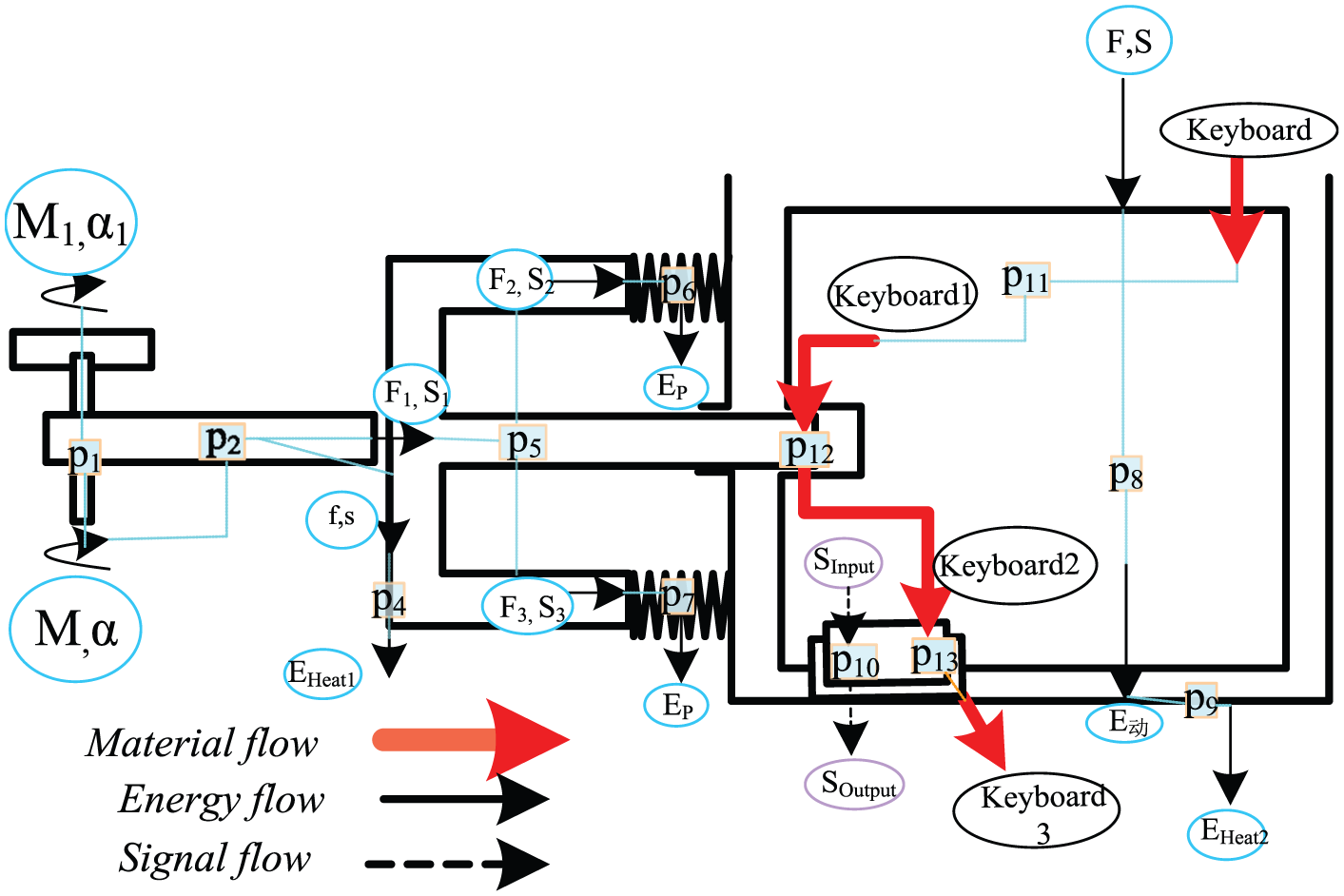
Step 3: Build the effectual action unit model. First, construct all effectual action units according to the construction form of the effectual action unit to form the corresponding knowledge base. Then, combine the effectual action units into the combined effectual action unit model through the conversion relationships among the energy, material, and signal. Finally, form the conversion relationship model diagram of the effectual action unit–based keyboard disassembly and assembly base.
Step 4: Construct the principle solution framework diagram. Formalize several effectual action units based on the structure-based conversion relationship model diagram to form the necessary geometries and material characteristics and to obtain the principle solutions. Then, combine various principle solutions through the conversion relationships to form the related combine principle solution. Finally, construct the principle solution framework diagram of the keyboard disassembly and assembly. Figure 6 shows the combined principle solution of the keyboard disassembly.
Step 5: Build the effect synthesis. Extract the effects in the structure base-keyboard disassembly principle solution framework diagram to obtain the effect synthesis of the keyboard disassembly and assembly.
Step 6: Build the function unit synthesis. First, construct the principle solution unit to which the effect units in the effect synthesis correspond to. Second, induce the possible function units to form several function unit chains according to the effect and geometric information stored by the principle solutions and then determine the logic relationships among the function units after analysis. For example, the effect of Hooke’s Law in the spring compression action unit may correspond to the possible function units of storing potential energy and shortening distance, whereas the function units of the positioning keyboard and locking slider have a parent–child relationship. Table 3 shows the function unit list of the new laptop, where f0112 is the number of the function units, the subscript 0112 indicates that the number of the principle solution is 01, and 1 is the function unit number of the corresponding principle solution, which belongs to the second category among the eight categories of function units. Finally, connect various function chains through the logical relationships among various function units to form the function unit synthesis diagram corresponding to the structure base. Figure 7 shows the function unit synthesis diagram of the keyboard disassembly and assembly.
Step 7: Build the functional structure framework. Acquire the various function unit synthesis diagrams previously obtained from the functional structure framework of each structure base using the inverse solving model. Figure 8 shows the functional structure framework diagram of the keyboard disassembly and assembly.

Inverse solving prototype system.
Database tables of prototype system.

Combined principle solution: keyboard disassembly.
Function unit list of the new laptop.


Function unit synthesis diagram of the keyboard disassembly and assembly.

The functional structure framework of the keyboard disassembly and assembly.
Figures 9 and 10 show the solving process of the prototype system.

Interface of action unit modeling.

Interface of effectual action unit modeling.
Discussion
This article proposes the effectual action unit–based inverse method for solving the functional structure of design history. Although it aims to understand and reuse the design intent of historical designs, same as typical structure–behavior–function (SBF) solving methods like SBF programming language, 27 the main advantages of our modeling idea and design solving process have the following superiorities in comparison with SBF programming language.
First, effectual action unit takes “effect” rather than “behavior” in SBF programming as the bridge between product structure and function. Behavior reflects the state change of the evolution from function to structure and the function–structure property parameters. It represents the dynamics of design solving. However, it is difficult to capture the intent of available product designs through behavior in SBF programming, especially complicated products as it is a time-consuming task to recognize each behavior of complicated structure and realized functions. This depends more on designers’ experiences with weak reproducibility. During the practical product design, the input and output parameters of the “effect” of each function in the conceptual design are the premise of gaining the rough structure of this function in subsequent detailed design. Therefore, this article uses “effect” to connect functions and structure of historical designs. The structural parameters of historical designs can be matched with the input and output of the corresponding function through the effectual action unit, thus enabling to get structure–effect–function inverse mapping relationship. This can help to recall and reuse function of each historical structure design.
Second, when building the effectual action unit, structural ties between parts are measured using the DSM. DSM can reflect the structural ties between parts objectively and avoid subjective processing results caused using SBF programming language. The most difficult thing in establishing the structure–principle–effect–function inverse solving model of available designs is how to process the complicated structural ties of available designs to deduce the initial design intent of designers. However, SBF programming language didn’t involve how to establish the structural ties between parts. It focuses on establishing the SBF mapping relationship, but lacks detailed rules and regulations for practical operation. The proposed effectual action unit can analyze the energy, material, signal, and spatial relationship between parts of historical designs by building DSM and gain the basic structure of these historical designs. Furthermore, based on the basic structure and input–output matching of “effect,” the principle and function prototype of the structure can be established preliminarily.
Third, the effectual action unit–based functional structure model of design history not only can understand their design intent better but also makes the historical designs easy to be reused in new product design. In fact, the proposed structure–principle–effect–function inverse solving model of historical designs establishes an inverse structure–principle–effect–function relationship of mature historical designs rather than follows the positive design process from product function design-principle design-structure design. The initial conditions for modeling only involve the structure of historical designs. Some or all of input and output parameters, principles, and effects added during the modeling can be reused in associated new product design. The follow-up work will focus on the reuse and mutation of functions in order to solve the local demand-varying designs quickly and effectively.
Conclusion
The effectual action unit can effectively and formally express the relationship between the input and output flows in the functional structure. Moreover, the effectual action unit can be used to induce the principle solution and realize such structure from the design history structure. The example shows that two inverse solution processes of structure–principle solution and principle solution–effect–function can effectively trace and capture the design intent of the historical products. These results will be helpful for solving the local demand-varying design. The follow-up work will focus again on the obtained functional structure to find the inverse solution process–based design intent capture strategy.
Footnotes
Academic Editor: Stephen D Prior
Declaration of conflicting interests
The author(s) declared no potential conflicts of interest with respect to the research, authorship, and/or publication of this article.
Funding
The author(s) disclosed receipt of the following financial support for the research, authorship, and/or publication of this article: This research work was supported by the National Natural Science Foundation of China (51375451 and 51005211).